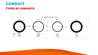
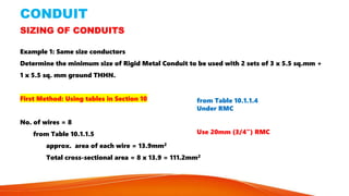
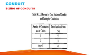
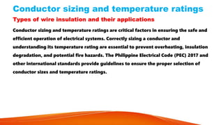
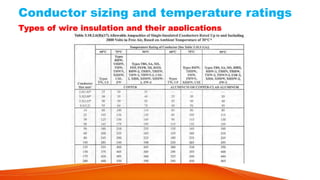
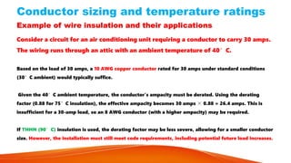
Chapter 3 of the Philippine Electrical Code (PEC) 2017 outlines standards for wiring methods and materials for safe electrical installations in various settings. It details different wiring methods including open and concealed wiring, surface and underground installations, and specifies the use of conduits and cable trays for organizing and protecting electrical cables. The chapter also covers guidelines on conductor sizing, insulation types, and requirements to prevent physical damage to wiring systems.