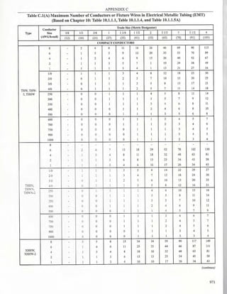
The 2017 edition of the Philippine Electrical Code (PECL 2017) is a comprehensive revision of the previous 2009 edition, now formatted in a single volume with new chapters and sections addressing key updates in electrical standards. Major changes include new definitions, the adoption of the National Electrical Code 2017, and significant revisions in various chapters pertaining to definitions, ampacity, and protective devices among others, ensuring relevance to the Philippine environment and practices. This edition aims to clarify ambiguities in the code and enhance the understanding and application of electrical engineering standards in the Philippines.


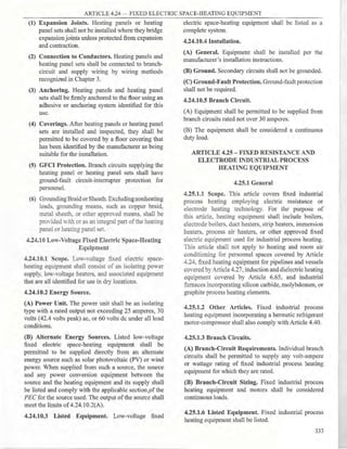
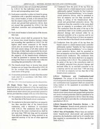
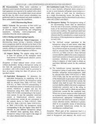
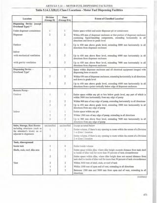
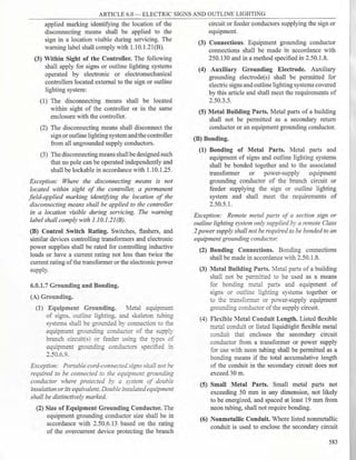
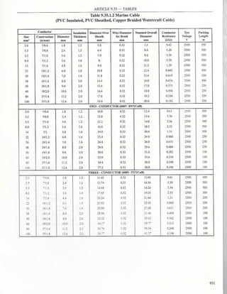
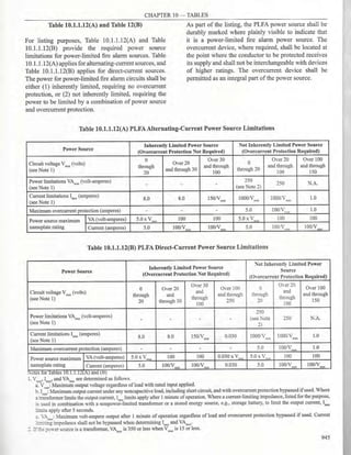
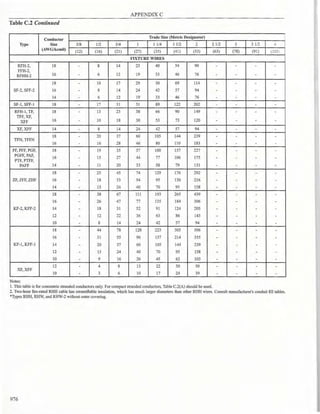
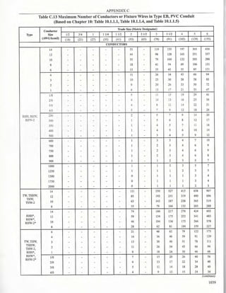
![PIDLIPPINE ELECTRICAL CODE 1 COMMITTEE
INSTITUTE OF INTEGRATED ELECTRICAL ENGINEERS OF THE PHILS., INC. (IIEE)
41 Monte de Piedad St., Cubao, Quezon City
FORM FOR PEC REVISION PROPOSALS
Date: ~------
Name : Tel No.
- -- - -- - -- - -~ - - - - - - - -
Address:
- - --- - --- ------------
Representing (Please indicate organization, company or self)
I. Reference:
1. PEC Part No. , Year
~ - - -~-
2. Article/Part/Section
------------
II. Proposal Recommends: (Check One)
n new text
fJ revised text
C deleted text
Ill. Proposal (Include proposed new or revised wording, or identification ofwording to be deleted):
[Use separate pages if space is inadequate]
IV. Statement ofProblem and Substantiation for Proposal:
V.
D This Proposal is original material.
D This proposal is not original material; its sources (ifknown) is as follows ___ ___ ___
I agree to give IIEE all and full rights, including rights of copyright, in this Proposal and I understand that
I acquire no rights in any publication of IIEE in which in this Proposal in this or another similar or analogous form is
used.
Signature
PLEASE USE SEPARATE FORM FOR EACH PROPOSAL
X](https://image.slidesharecdn.com/pec2017part1-241003060423-f7360a96/85/Philllipine-electrical-code-2017-PART-1-pdf-11-320.jpg)


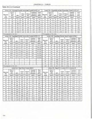
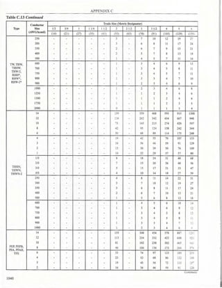
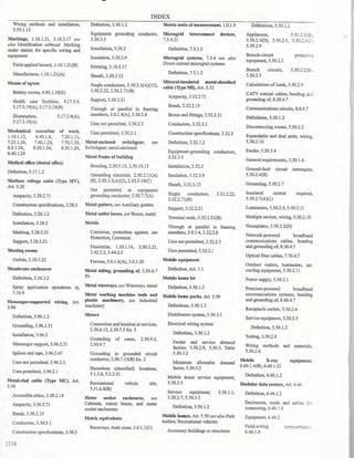
![ARTICLE 1.1 - DEFINITIONS
the qualifications to the registration and licensure
examinations for Registered Master Electrician
(RME), in order to practice electrical engineering in
the Philippines. Knowledge and understanding of the
Philippine Electrical Code, Parts 1 and 2 (PECl and
PEC2) form part ofthe examinations given.
(B) An apprentice shall undergo training under a
person holding a valid certificate of registration and a
valid professional license for the practice of electrical
engineering under Republic Act 7920 or the national
electrical engineering Jaw.
1.0.1.11 Services of Licensed Electrical Practitioner.
For decisions and actions involving a knowledge
of electrical engineering and/or training in electrical
installations and practices, the services of a licensed
electrical practitioner is required.
ARTICLE 1.1 - DEFINITIONS
1.1.1.1 Scope. This article contains only those
definitions essential to the application ofthis Code. It is
not intended to include commonly defined general terms
or commonly defined technical terms from related codes
and standards. In general, only those terms that are used
in two or more articles are defined in Article 1.1. Other
definitions are included in the article in which they are
used but may be referenced in Article 1.1.
Part 1.1.1 of this article contains definitions intended
to apply wherever the tem1s are used throughout this
Code. Part 1.1.2 contains definitions applicable to the
installations and equipment operating at over 1000
volts, nominal.
1.1.1 General
Accessible (as applied to equipment). Admitting close
approach; not guarded by locked doors, elevation, or
other effective means.
Accessible (as applied to wiring methods). Capable
of being removed or exposed without damaging the
building structure or finish or not permanently closed in
by the structure or finish ofthe building.
Accessible, Readily (Readily Accessible). Capable
of being reached quickly for operation, renewal, or
inspections without requiring those to whom ready
access is requisite to take actions such as to use tools
(other than keys), to climb over or under, to remove
obstacles or to resort to portable ladders, and so forth.
FPN: Use of keys is a common practice under controlled or
supervised conditions and a common alternative to the ready
access requirements under such supervised conditions as provided
elsewhere in the NEC
Adjustable Speed Drive. Power conversion equipment
that provides a means of adjusting the speed of an
electric motor.
FPN: A variable frequency drive is one type of electronic adjustable
speed drive that controls the rotational speed of an ac electric motor by
controlling the frequency and voltage of the electrical power supplied to
the motor.
Ampacity. The current, in amperes, that a conductor
can carry continuously under the conditions of use
without exceeding its temperature rating.
Appliance. Utilization equipment, generally other than
industrial, that is normally built in standardized sizes or
types and is installed or connected as a unit to perform
one or more functions such as clothes washing, air
conditioning, food mixing, deep frying, and so forth.
Approved. Equipment and materials; and installation,
testing and commissioning methods, recognized as
acceptable by local and international standards-setting
organizations - properly equipped and qualified for
testing, inspections of the run ofgoods at factories, and
service-value determination through field inspections
- and/or as permitted by relevant and applicable
government regulatory codes.
FPN: An example of government regulatory codes are the
Philippine Electrical Code, Part I and Part 2.
Askarel. A generic term for a group of nonflammable
synthetic chlorinated hydrocarbons used as electrical
insulating media.
FPN: Askarels of various compositional types are used. Under arcing
conditions, the gases produced, while consisting predominantly of
noncombustible hydrogen chloride, can include varying amounts of
combustible gases, depending on the askarel type.
Associated Apparatus [as applied to Hazardous
(Classified) Locations]. Apparatus in which the circuits
are not necessarily intrinsically safe themselves but that
affects the energy in the intrinsically safe circuits and is
relied on to maintain intrinsic safety. Such apparatus is
one of the following:
(1) Electrical apparatus that has an alternative type
ofprotection for use in the appropriate hazardous
(classified) location
(2) Electrical apparatus not so protected that shall not
be used within a hazardous (classified) location
FPN No. 1: Associated apparatus has identified intrinsically safe
connections for intrinsically safe apparatus and also may have
connections for nonintrinsically safe apparatus.
FPN No. 2: An example of associated apparatus is an intrinsic
safety barrier, which is a network designed to limit the energy
(voltage and current) available to the protected circuit in the
hazardous (classified) location, under specified fault conditions.
3](https://image.slidesharecdn.com/pec2017part1-241003060423-f7360a96/85/Philllipine-electrical-code-2017-PART-1-pdf-26-320.jpg)
![ARTICLE 1.1 - DEFINITIONS
Associated Nonincendive Field Wiring Apparatus
[as applied to Hazardous (Classified) Locations].
Apparatus in which the circuits are not necessarily
nonincendive themselves but that affect the energy in
nonincendive field wiring circuits and are relied upon
to maintain nonincendive energy levels. Such apparatus
are one of the following:
(1) Electrical apparatus that has an alternative type
ofprotection for use in the appropriate hazardous
(classified) location
(2) Electrical apparatus not so protected that shall not
be used in a hazardous (classified) location
FPN: Associated nonincendive field wiring apparatus has
designated associated nonincendive field wiring apparatus
connections for nonincendive field wiring apparatus and may also
have connections for other electrical apparatus.
Attachment Plug (Plug Cap) (Plug). A device that,
by insertion in a receptacle, establishes a connection
between the conductors ofthe attached flexible cord and
the conductors connected permanently to the receptacle.
Automatic. Performing a function without the necessity
ofhuman intervention.
Bathroom. An area including a basin with one or more
of the following: a toilet, a tub, or a shower.
Battery System. Interconnected battery subsystems
consisting of one or more storage batteries and battery
chargers, and can include inverters, converters, and
associated electrical equipment.
Bonded (Bonding). Connected to establish electrical
continuity and conductivity.
Bonding Conductor or Jumper. A reliable conductor
to ensure the required electrical conductivity between
metal parts required to be electrically connected.
Bonding Jumper, Equipment. The connection
between two or more portions of the equipment
grounding conductor.
Bonding Jumper, Main. The connection between
the grounded circuit conductor and the equipment
grounding conductor at the service.
Bonding Jumper, System. The connection between
the grounded circuit conductor and the equipment
grounding conductor at a separately derived system.
Branch Circuit. The circuit conductors between the
final overcurrent device protecting the circuit and the
outlet(s).
Branch Circuit, Appliance. A branch circuit that
supplies energy to one or more outlets to which
appliances are to be connected and that has no
permanently connected luminaires that are not a part of
an appliance.
4
Branch Circuit, General-Purpose. A branch circuit
that supplies two or more receptacles or outlets for
lighting and appliances.
Branch Circuit, Individual. A branch circuit that
supplies only one utilization equipment.
Branch Circuit, Multiwire. A branch circuit that
consists of two or more ungrounded conductors that
have a voltage between them, and a grounded conductor
that has equal voltage between it and each ungrounded
conductor of the circuit and that is
Building. A structure that stands alone or that is
separated from adjoining structures by fire walls.
Building Official. The government official appointed
by the Secretary of the Department of Public Works
and who is responsible for enforcing the provisions of
the National Building Code of the Philippines (NBC)
created under Presidential Decree 1096 (PD 1096) and
its Implementing Rules and Regulations; and charged
with the duties of issuing building permits, notices and
certificates.
Building Official, Office of the. The place of business
of the Building Official where processing of permits,
notices, certificates and other related documents are
undertaken. Also referred to as OBO in this Code.
Building Official/EE, Office of the. A licensed
electrical practitioner employed in the Office of the
Building Official responsible for overseeing electrical
installations and equipmentfor complianceto provisions
of the Philippine Electrical Code, Part 1 (PECl), and
for the approval of electrical permits and certificates
issuances. Also referred to as OBO/EE in this Code.
FPN: A licensed electrical practitioner is a Registered Master
Electrician (RME), Registered Electrical Engineer (REE) or
Professional Electrical Engineer (PEE) under Republic Act
7920 or national electrical engineering law with their respective
duties and responsibilities. See definition of Licensed Electrical
Practitioner.
Cabinet. An enclosure that is designed for either
surface mounting or flush mounting and is provided
with a frame, mat, or trim in which a swinging door or
doors are or can be hung.
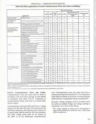
CableRoutingAssembly.Asinglechannelorconnected
multiple channels, as well as associatedfittings, forming
a structural system that is used to support and route
communications wires and cables, optical fiber cables,
data cables associated with information technology and
communications equipment, Class 2, Class 3, and Type
PLTC cables, and power-limited fire alarm cables in
plenum, riser, and general-purpose applications.](https://image.slidesharecdn.com/pec2017part1-241003060423-f7360a96/85/Philllipine-electrical-code-2017-PART-1-pdf-27-320.jpg)
![ARTICLE 1.1 - DEFINITIONS
Charge Controller. Equipment that controls de voltage
or de current, or both, and that is used to charge a battery
or other energy storage device.
Circuit Breaker. A device designed to open and close
a circuit by nonautomatic means and to open the circuit
automatically on a predetermined overcurrent without
damage to itselfwhen properly applied within its rating.
FPN: The automatic opening means can be integral, direct
acting with the circuit breaker, or remote from the circuit
breaker when properly applied within its rating.
Adjustable (as applied to circuit breakers). A
qualifying term indicating that the circuit breaker
can be set to trip at various values ofcurrent, time, or
both, within a predetermined range.
Instantaneous Trip (as applied to circuit breakers).
Aqualifying term indicating that no delay is purposely
introduced in the tripping action ofthe circuit breaker.
Inverse Time (as applied to circuit breakers). A
qualifying term indicating that there is purposely
introduced a delay in the tripping action ofthe circuit
breaker, which delay decreases as the magnitude of
the current increases.
Nonadjustable (as applied to circuit breakers). A
qualifying term indicating that the circuit breaker
does not have any adjustment to alter the value of
current at which it will trip or the time required for
its operation.
Setting (of circuit breakers). The value of current,
time, or both, at which an adjustable circuit breaker
is set to trip.
Clothes Closet. A nonhabitable room or space intended
primarily for storage ofgarments and apparel
Coaxial Cable. A cylindrical assembly composed of
a conductor centered inside a metallic tube or shield,
separated by a dielectric material, and usually covered
by an insulating jacket.
Combustible Dust [as applied to Hazardous
(Classified) Locations]. Dust particles that are 500
microns or smaller (i.e., material passing a U.S. No.
35 Standard Sieve as defined in ASTM Ell-2015,
Standard Specification for Woven Wire Test SieveCloth
and Test Sieves), and present a fire or explosion hazard
when dispersed and ignited in air.
FPN: See ASTM El226-2012a, Standard Test Method for
Explosibility of Dust Clouds, or ISO 6184-l, Explosion
protection systems - Part 1: Determination ofexplosion indices
of combustible dusts in air, for procedures for determining the
explosibility ofdusts.
Combustible Gas Detection System [as applied to
Hazardous (Classified) Locations]. A protection
technique utilizing stationary gas detectors in industrial
establishments.
Communications Equipment. The electronic
equipment that performs the telecommunications
operations for the transmission of audio, video, and
data, and includes power equipment (e.g., de converters,
inverters, and batteries), technical support equipment
(e.g., computers), and conductors dedicated solely to
the operation ofthe equipment.
FPN: As the telecommunications network transitions to a more
data-centric network, computers, routers, servers, and their
powering equipment, are becoming essential to the transmission
ofaudio, video, and data and are finding increasing application in
communications equipment installations.
Composite Optical Fiber Cable. A cable containing
optical fibers and current-carrying electrical conductors.
Concealed. Rendered inaccessible by the structure or
finish of the building. Wires in concealed raceways are
considered concealed, even though they may become
accessible by withdrawing them.
Conductive Optical Fiber Cable. A factory assembly
ofone or more optical fibers having an overall covering
and containing non- current-carrying conductive
member(s) such as metallic strength member(s),
metallic vapor barrier(s), metallic armor or metallic
sheath.
Conductor, Bare. A conductor having no covering or
electrical insulation whatsoever.
Conductor, Covered. A conductor encased within
material of composition or thickness that is not
recognized by this Code as electrical insulation.
Conductor, Insulated. A conductor encased within
material ofcomposition and thickness that is recognized
by this Code as electrical insulation.
Conduit Body. A separate portion of a conduit or
tubing system that provides access through a removable
cover(s) to the interior ofthe system at ajunction oftwo
or more sections of the system or at a terminal point of
the system.
Boxes such as FS and FD or larger cast or sheet metal
boxes are not classified as conduit bodies.
Connector, Pressure (Solderless). A device that
establishes a connection between two or more
conductors or between one or more conductors and a
terminal by means of mechanical pressure and without
the use ofsolder.
Continuous Load. A load where the maximum current
is expected to continue for 3 hours or more.
5](https://image.slidesharecdn.com/pec2017part1-241003060423-f7360a96/85/Philllipine-electrical-code-2017-PART-1-pdf-28-320.jpg)
![ARTICLE 1.1 - DEFINITIONS
Control Circuit. The circuit of a control apparatus
or system that carries the electric signals directing the
performance of the controller but does not carry the
main power current.
Control Drawing [as applied to Hazardous
(Classified) Locations]. A drawing or other document
provided by the manufacturer ofthe intrinsically safe or
associatedapparatus, or ofthe nonincendive field wiring
apparatus or associated nonincendive field wiring
apparatus, that details the allowed interconnections
between the intrinsically safe and associated apparatus
or between the nonincendive field wiring apparatus or
associated nonincendive field wiring apparatus.
Controller. A device or group of devices that serves
to govern, in some predetermined manner, the electric
powerdelivered to the apparatus to which itis connected.
Cooking Unit, Counter-Mounted. A cooking
appliance designed for mounting in or on a counter and
consisting of one or more heating elements, internal
wiring, and built-in or mountable controls.
Coordination, Selective (Selective Coordination).
Localization of an overcunent condition to restrict
outages to the circuit or equipment affected,
accomplished by the selection and installation of
overcurrent protective devices and their ratings or
settings for the full range of available overcurrents,
from overload to the maximum available fault current,
and for the full range of overcurrent protective device
opening times associated with those overcurrent.
Copper-Clad Aluminum Conductors. Conductors
drawn from a copper-clad aluminum rod with the
copper metallurgically bonded to an aluminum core,
where copper fmms a minimum of IO percent of the
cross-sectional area of a solid conductor or each strand
of a stranded conductor.
CordConnector [as applied to Hazardous (Classified)
Locations]. A fitting intended to terminate a cord to a
box or similar device and reduce the strain at points of
termination and may include an explosionproof, a dust-
ignitionproof, or a flameproof seal.
Cutout Box. An enclosure designed for surface
mounting that has swinging doors or covers secured
directly to and telescoping with the walls of the
enclosure.
Dead Front. Without live parts exposed to a person on
the operating side of the equipment.
Demand Factor. The ratio of the maximum demand of
a system, or part ofa system, to the total connected load
ofa system or the partofthe system under consideration.
6
Device. A unit of an electrical system, other than a
conductor, that is intended to carry or control but not
utilize electric energy.
Disconnecting Means. A device, or group of devices,
or other means by which the conductors ofa circuit can
be disconnected from their source of supply.
Dust-Ignitionproof [as applied to Hazardous
(Classified) Locations]. Equipment enclosed in a
manner that excludes dusts and does not permit arcs,
sparks, or heat otherwise generated orliberated inside of
the enclosure to cause ignition ofexterior accumulations
or atmospheric suspensions of a specified dust on or in
the vicinity ofthe enclosure.
FPN: For further information on dust-ignitionproof enclosures,
see ANSI/UL 1202-2013, Enclosures for Electrical Equipment,
andANSI/UL 1203-2013, ExplosionproofandDust-Jgnitionproof
Electrical Equipment/or Hazardous (Classified) Locations.
Dusttight. Enclosures constructed so that dust will not
enter the enclosing case under specified test conditions.
FPN No. 1: Enclosure Types 3, 3S, 3SX, 4, 4X, 5, 6, 6P, 12, 12K,
and 13, per ANSI/NEMA 250-2014, Enclosures for Electrical
Equipment, are considered dusttight and suitable for use in
unclassified locations and in Class II, Division 2; Class III; and
Zone 22 hazardous (classified) locations.
FPN No. 2: For further information, see ANSV ISA-12.12.01-
2013, Nonincendive Electrical Equipment for Use in Class I
and IL Division 2, and Class III, Divisions 1 and 2 Hazardous
(Classified) Locations.
Duty, Continuous. Operation at a substantially constant
load for an indefinitely long time.
Duty, Intermittent. Operation for alternate intervals of
(1) load and no load; or (2) load and rest; or (3) load, no
load, and rest.
Duty, Periodic. Intermittent operation in which the
load conditions are regularly recurrent.
Duty, Short-Time. Operation at a substantially constant
load for a short and definite, specified time.
Duty, Varying. Operation at loads, and for intervals of
time, both ofwhich may be subject to wide variation.
Dwelling Unit. A single unit, providing complete and
independent living facilities for one or more persons,
including permanent provisions for living, sleeping,
cooking, and sanitation.
Dwelling, One-Family. A building that consists
solely ofone dwelling unit.
Dwelling, Two-Family. A building that consists
solely of two dwelling units.
Dwelling, Multifamily. A building that contains three
or more dwelling units.](https://image.slidesharecdn.com/pec2017part1-241003060423-f7360a96/85/Philllipine-electrical-code-2017-PART-1-pdf-29-320.jpg)
![ARTICLE 1.1 - DEFINITIONS
further information, see UL 943, Standard for Ground-Fault
Circuit Interrupters.
Ground-Fault Current Path. An electrically
conductive path from the point of a ground fault on a
wiring system through normally non-current-carrying
conductors, equipment, or the earth to electrical supply
source.
FPN: Examples of ground-fault current paths are any
combination of equipment grounding conductors, metallic
raceways, metallic cable sheaths, electrical equipment, and
any other electrically conductive material such as metal, water,
and gas piping; stucco mesh; metal ducting; reinforcing steel;
shields ofcommunications cables; and the earth itself.
Ground-Fault Protection of Equipment. A system
intended to provide protection of equipment from
damaging line-to-ground fault currents by operating to
cause a disconnecting means to open all ungrounded
conductors of the faulted circuit. This protection is
provided at current levels less than those required to
protect conductors from damage through the operation
ofa supply circuit overcurrent device.
Grounding Conductor, Equipment (EGC). The
conductive path(s) that provides a ground-fault current
path and connects normally non-current-carrying metal
parts ofequipment together and to the system grounded
conductor or to the grounding electrode conductor, or
both.
FPN No. 1: It is recognized that the equipment grounding
conductor also performs bonding.
FPN No. 2: See 2.50.6.9 for the list of acceptable equipment
grounding conductors.
Grounding Electrode. A device that establishes an
electrical connection to the earth.
Grounding Electrode Conductor. The conductor used
to connect the grounding electrode(s) to the equipment
grounding conductor, to the grounded conductor, or to
both, at the service, at each building or structure where
supplied by a feeder(s) or branch circuit(s), or at the
source of a separately derived system.
Guarded. Covered, shielded, fenced, enclosed, or
otherwise protected by means of suitable covers,
casings, barriers, rails, screens, mats, or platforms to
remove the likelihood ofapproach or contact by persons
or objects to a point ofdanger.
Guest Room. An accommodation combining living,
sleeping, sanitary, and storage facilities within a
compartment.
Guest Suite. An accommodation with two or more
contiguous rooms comprising a compartment, with or
without doors between such rooms, that provides living,
sleeping, sanitary, and storage facilities.
8
Handhole Enclosure.An enclosure identified for use in
underground systems, provided with an open or closed
bottom, and sized to allow personnel to reach into, but
not enter, for the purpose of installing, operating, or
maintaining equipment or wiring or both.
Hermatic Refrigerant Motor-Compressor. A
combination consisting of a compressor and motor,
both ofwhich are enclosed in the same housing, with no
external shaft or shaft seals, with the motor operating in
the refrigerant.
Hermetically Sealed [as applied to Hazardous
(Classified) Locations]. Equipment sealed against the
entrance of an exter- nal atmosphere where the seal
is made by fusion, for example, soldering, brazing,
welding, or the fusion of glass to metal.
FPN: For further information, see Al"l'SI/ ISA-12.12.01-2013,
Nonincendive Electrical Equipment for Use in Class I and
II, Division 2, and Class Ill, Divisions 1 and 2 Hazardous
(Classified) Locations.
Hoistway. Any shaftway, hatchway, well hole, or
other vertical opening or space in which an elevator or
dumbwaiter is designed to operate.
Hybrid System. A system comprised of multiple
power sources. These power sources could include
photovoltaic, wind, micro-hydro generators, engine-
driven generators, and others, but do not include electric
power production and distribution network systems.
Energy storage systems such as batteries, :flywheels,
or superconducting magnetic storage equipment do
not constitute a power source for the purpose of this
definition. The energy regenerated by an overhauling
(descending) elevator does not constitute a power
source for the purpose ofthis definition.
Identified (as applied to equipment). Recognizable
as suitable for the specific purpose, function, use,
environment, application, and so forth, where described
in a particular Code requirement.
FPN: Some examples of ways to determine suitability of
equipment for a specific purpose, environment, or application
include investigations by a qualified testing laboratory (listing
and labeling), an inspection agency, or other organizations
concerned with product evaluation.
In Sight From (Within Sight From, Within Sight).
Where this Code specifies that one equipment shall
be "in sight from," "within sight from," or "within
sight," and so forth, ofanother equipment, the specified
equipment is to be visible and not more than 15 m
distant from the other.
Industrial Control Panel. An assembly of two or
more components consisting of one of the following:
(1) power circuit components only, such as motor
controllers, overload relays, fused disconnect switches,](https://image.slidesharecdn.com/pec2017part1-241003060423-f7360a96/85/Philllipine-electrical-code-2017-PART-1-pdf-31-320.jpg)
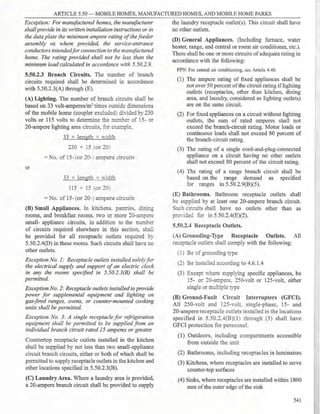
![ARTICLE 1.1 - DEFINITIONS
and circuit breakers; (2) control circuit components
only, suchas push buttons,pilot lights, selector switches,
timers, switches, and control relays; (3) a combination
of power and control circuit components. These
components, with associated wiring and terminals,
are mounted on, or contained within, an enclosure or
mounted on a subpanel.
The industrial control panel does not include the
controlled equipment.
InformationTechnologyEquipment(ITE).Equipment
and systems rated 1000 volts or less, normally found
in offices or other business establishments and similar
environments classified as ordinary locations, that
are used for creation and manipulation of data, voice,
video, and similar signals that are not communications
equipment as defined in Part 1.0.1 and do not process
communications circuits as defined in 8.0.1.2.
FPN: For informationonlisting requirements for both information
technology equipment and communications equipment, see UL
60950-1-2014, Information Technology Equipment - Safety -
Part 1: General Requirements or UL 62368-1-2014, Audio/Video
Infonnation and Communication Technology Equipment Part 1:
Safety Requirements.
Innerduct. A nonmetallic raceway placed within a
larger raceway.
Interactive Inverter. An inverter intended for use in
parallel with an electric utility to supply common loads
that may deliver power to the utility.
Interactive System. An electric power production
system that is operating in parallel with and capable of
delivering energy to an electric primary source supply
system.
Interrupting Rating. The highest current at rated
voltage that a device is intended to interrupt under
standard test conditions.
FPN: Equipment intended to interrupt current at other than
fault levels may have its interrupting rating implied in other
ratings, such as horsepower or locked rotor current.
Intersystem Bonding Termination. A device that
provides a means for connecting intersystem bonding
conductors for communications systems to the
grounding electrode system.
Intrinsically Safe Apparatus. Apparatus in which all
the circuits are intrinsically safe.
Intrinsically Safe System [as applied to Hazardous
(Classified) Locations].An assembly ofinterconnected
intrinsically safe apparatus, associated apparatus, and
interconnecting cables, in that those parts ofthe system
that may be used in hazardous (classified) locations are
intrinsically safe circuits.
FPN: An intrinsically safe system may include more than one
intrinsically safe circuit.
Isolated (as applied to location).Not readily accessible
to persons unless special means for access are used.
Kitchen. An area with a sink and permanent provisions
for food preparation and cooking.
Labeled. Equipment or materials to which has been
attached a label, symbol, or other identifying mark ofan
organization that is concerned with product evaluation,
that maintains periodic inspection of production of
labeled equipment or materials, and by whose labeling
the manufacturer indicates compliance with appropriate
standards or performance in a specified manner.
Lighting Outlet. An outlet intended for the direct
connection of a lampholder, a luminaire (lighting
fixture), or a pendant cord terminating in a lampholder.
Lighting Track (Track Lighting). A manufactured
assembly designed to support and energize luminaires
that are capable of being readily repositioned on
the track. Its length can be altered by the addition or
subtraction of sections of track.
Listed. Equipment, materials, or services included in
<1:. list published by an organization that is concerned
with evaluation of products or services, that maintains
periodic inspection ofproduction oflisted equipment or
materials or periodic evaluation ofservices, and whose
listing states that the equipment, material, or services
either meets appropriate designated standards or has
been tested and found suitable for a specified purpose.
FPN: The means for identifying listed equipment may vary
for each organization concerned with product evaluation,
some of which do not recognize equipment as listed unless
it is also labeled. Use of the system employed by the listing
organization allows the Office of the Building Official/EE to
identify a listed product.
Live Parts. Energized conductive components.
FPN: Examples of such locations include partially protected
locations under canopies, marquees, roofed open porches, and
like locations, and interior locations subject to moderate degrees
ofmoisture, such as some basements, somebarns, and some cold-
storage warehouses.
Location, Damp. Locations protected from weather
and not subject to saturation with water or other liquids
but subject to moderate degrees ofmoisture.
FPN: Examples of such locations include partially protected
locations under canopies, marquees, roofed open porches, and
like locations, and interior locations subject to moderate degrees
ofmoisture, such as some basements, somebarns, andsome cold-
storage warehouses.
Location, Dry. A location not normally subject to
dampness or wetness. A location classified as dry may
be temporarily subject to dampness or wetness, as in the
case ofa building under construction.
9](https://image.slidesharecdn.com/pec2017part1-241003060423-f7360a96/85/Philllipine-electrical-code-2017-PART-1-pdf-32-320.jpg)
![ARTICLE 1.1 - DEFINITIONS
Location, Wet. Installations underground or in
concrete slabs or masonry in direct contact with the
earth; in locations subject to saturation with water or
other liquids, such as vehicle washing areas; and in
unprotected locations exposed to weather.
Luminaire. A complete lighting unit consisting of
a lamp or lamps together with the parts designed to
distribute the light, to position and protect the lamps
and ballast (where applicable), and to connect the lamps
to the power supply.
Mobile Equipment. Equipment with electrical
components suitable to be moved only with mechanical
aids or is provided with wheels for movement by
person(s) or powered devices.
Motor Control Center. An assembly of one or more
enclosed sections having a common power bus and
principally containing motor control units.
Multioutlet Assembly. A type of surface, flush, or
freestanding raceway designed to hold conductors and
receptacles, assembled in the field or at the factory.
National Electrical Engineering Law. A law enacted
by Congress providing for a more responsive and
comprehensive regulation for the practice, licensing
and registration of electrical engineers and electricians
otherwise referred to as Republic Act 7920 (RA 7920)
or a future law that supersedes it.
Neutral Conductor. The conductor connected to the
neutral point ofa system that is intended to carry current
under normal conditions.
Neutral Point. The common point on a wye-connection
in a polyphase system or midpoint on a single-phase,
3-wire system, or midpoint of a single-phase portion
of a 3-phase delta system, or a midpoint of a 3-wire,
direct-current system.
FPN: At the neutral point ofthe system, the vectorial sum
of the nominal voltages from all other phases within the
system that utilize the neutral, with respect to the neutral
point, is zero potential.
Nonautomatic. Requiring human intervention to
perform a function.
Nonconductive Optical Fiber Cable. A factory
assembly ofone or more optical fibers having an overall
covering and containing no electrically conductive
materials.
Nonincendive Circuit [as applied to Hazardous
{Classified) Locations]. A circuit, other than field
wiring, in which any arc or thermal effect produced
underintended operating conditionsofthe equipment, is
not capable, under specified test conditions, of igniting
10
the flammable gas- air, vapor-air, or dust- air mixture.
FPN: Conditions are described in ANSI/ ISA-12.12.01-2013,
Nonincendive Electrical Equipment for Use in Class I and
II, Division 2, and Class 111, Divisions I and 2 Hazardous
(Classified) Locations.
Nonincendive Component [as applied to Hazardous
(Classified) Locations]. A component having
contacts for making or breaking an incendive circuit
and the contacting mechanism is constructed so that
the component is incapable of igniting the specified
flammable gas- air or vapor- air mixture. The housing
ofa nonincendive component is not intended to exclude
the flammable atmosphere or contain an explosion.
FPN: For further information, see ANSI/ ISA-12.12.01-2013,
Nonincendive Electrical Equipment for Use in Class I and
II, Division 2, and Class 111, Divisions I and 2 Hazardous
(Classified) Locations.
Nonincendive Equipment [as applied to Hazardous
(Classified) Locations]. Equipment having electrical/
electronic circuitry that is incapable, under normal
operating conditions, of causing ignition of a specified
flammable gas-air, vapor- air, or dust-air mixture due
to arcing or thermal means.
FPN: For further information, see ANSI/ ISA-12.12.01-2013,
Nonincendive Electrical Equipment for Use in Class I and
II, Division 2, and Class Ill, Divisions I and 2 Hazardous
(Classified) Locations.
Nonincendive Field Wiring [as applied to Hazardous
(Classified) Locations]. Wiring that enters or leaves
an equipment enclosure and, under normal operating
conditions of the equipment, is not capable, due to
arcing or thermal effects, ofigniting the flammable gas-
air, vapor- air, or dust-air mixture. Normal operation
includes opening,shorting, or grounding the field wiring.
Nonincendive Field Wiring Apparatus [as applied
to Hazardous {Classified) Locations]. Apparatus
intended to be connected to nonincendive field wiring.
FPN: For further information, see ANSI/ ISA-12.12.01-2013,
Nonincendive Electrical Equipment for Use in Class I and
11, Division 2, and Class III, Divisions I and 2 Hazardous
(Classified) Locations.
Nonlinear Load. A load where the wave shape of the
steady-state current does not follow the wave shape of
the applied voltage.
FPN: Electronic equipment, electronic/electric-discharge
lighting, adjustable-speed drive systems, andsimilarequipment
may be nonlinear loads.
Oil Immersion [as applied to Hazardous (Classified)
Locations]. Electrical equipment immersed in a
protective liquid in such a way that an explosive
atmosphere that may be above the liquid or outside the
enclosure cannot be ignited.](https://image.slidesharecdn.com/pec2017part1-241003060423-f7360a96/85/Philllipine-electrical-code-2017-PART-1-pdf-33-320.jpg)
![ARTICLE 1.1 - DEFINITIONS
Optical Fiber Cable. A factory assembly or field
assembly ofone or more optical fibers having an overall
covering.
FPN: A field-assembled optical fiber cable is an assembly ofone
or more optical fibers within a jacket. The jacket, without optical
fibers, is installed in a manner similar to conduit or raceway.
Once the jacket is installed, the optical fibers are inserted into the
jacket, completing the cable assembly.
Outlet. A point on the wiring system at which current is
taken to supply utilization equipment.
Outline Lighting. An arrangement of incandescent
lamps, electric discharge lighting, or other electrically
powered light sources to outline or call attention to
certain features such as the shape of a building or the
decoration ofa window.
Overcurrent. Any current in excess ofthe rated current
of equipment or the ampacity of a conductor. It may
result from overload, short circuit, or ground fault.
FPN: A current in excess ofrating may be accommodated by
certain equipment and conductors for a given set ofconditions.
Therefore, the rules for overcurrent protection are specific for
particular situations.
Overcurrent Protective Device, Branch-Circuit.
A device capable of providing protection for service,
feeder, and branch circuits and equipment over the full
range of overcurrents between its rated current and its
interrupting rating. Such devices are provided with
interrupting ratings appropriate for the intended use but
no less than 5000 amperes.
Overcurrent Protective Device, Supplementary.
A device intended to provide limited overcurrent
protection for specific applications and utilization
equipment such as lurninaires and appliances. This
limited protection is in addition to the protection
provided in the required branch circuit by the branch-
circuit overcurrent protective device.
Overload. Operation ofequipment in excess ofnormal,
full-load rating, or of a conductor in excess of rated
ampacity that, when it persists for a sufficient length of
time, would cause damage or dangerous overheating.
A fault, such as a short circuit or ground fault, is not an
overload.
Panelboard. A single panel or group of panel units
designed for assembly in the form of a single panel,
including buses and automatic overcurrent devices,
and equipped with or without switches for the control
of light, heat, or power circuits; designed to be placed
in a cabinet or cutout box placed in or against a wall,
partition, or other support; and accessible only from the
front.
Photovoltaic (PV) System. The total components and
subsystem that, in combination, convert solar energy
into electric energy suitable for connection to a
utilization load.
Plenum. A compartment or chamber to which one or
more air ducts are connected and that forms part of the
air distribution system.
Portable Equipment. Equipment with electrical
components suitable to be moved by a single person
without mechanical aids.
Power Outlet. An enclosed assembly that may include
receptacles, circuit breakers, fuseholders, fused
switches, buses, and watt-hour meter mounting means;
intended to supply and control power to mobile homes,
recreational vehicles, park trailers, or boats or to serve
as a means for distributing power required to operate
mobile or temporarily installed equipment.
Premises Wiring (System). That interior and exterior
wiring, including power, lighting, control, and signal
circuit wiring together with all their associated
hardware, fittings, and wiring devices, both permanently
and temporarily installed, that extends from the service
point or source of power, such as a battery, a solar
photovoltaic system, or a generator, transformer, or
converter windings, to the outlet(s).
Such wiring does not include wiring internal to
appliances, lurninaires (fixtures), motors, controllers,
motor control centers, and similar equipment.
FPN: Power sources include, but are not limited to,
interconnected or stand-alone batteries, solar photovoltaic
systems, other distributed generation systems, or generators.
Pressurized [as applied to Hazardous (Classified)
Locations]. The process of supplying an enclosure
with a protective gas with or without continuous
flow, at sufficient pressure to prevent the entrance of
combustible dust or ignitible fibers/ flyings.
Process Seal [as applied to Hazardous (Classified)
Locations]. A seal between electrical systems and
flammable or combustible process fluids where a failure
could allow the migration of process fluids into the
premises' wiring system.
Purged and Pressurized [as applied to Hazardous
(Classified) Locations]. The process of (1) purging,
supplying an enclosure with a protective gas at a
sufficient flow and positive pressure to reduce the
concentration of any flammable gas or vapor initially
present to an acceptable level; and (2) pressurization,
supplying an enclosure with a protective gas with or
without continuous flow at sufficient pressure to prevent
the entrance ofa flammable gas or vapor, a combustible
dust, or an ignitible fiber.
11](https://image.slidesharecdn.com/pec2017part1-241003060423-f7360a96/85/Philllipine-electrical-code-2017-PART-1-pdf-34-320.jpg)
![ARTICLE 1.1 - DEFINITIONS
Short-Circuit Current Rating. The prospective
symmetrical fault current at a nominal voltage to which
an apparatus or system is able to be connected without
sustaining damage exceeding defined acceptance
criteria.
Show Window. Any window used or designed to be
used for the display of goods or advertising material,
whether it is fully or partly enclosed or entirely open
at the rear and whether or not it has a platform raised
higher than the street floor level.
Signaling Circuit. Any electric circuit that energizes
signaling equipment.
Simple Apparatus [as applied to Hazardous
(Classified) Locations]. An electrical component or
combination of components of simple construction
with well-defined electrical parameters that does not
generate more than 1.5 volts, 100 mA, and 25 mW, or
a passive component that does not dissipate more than
1.3 watts and is compatible with the intrinsic safety of
the circuit in which it is used.
FPN: The following apparatus are examples of simple apparatus:
(1) Passive components; for example, switches,junction boxes,
resistance temperature devices, and simple semiconductor
devices such as LEDs
(2) Sources ofstored energy consisting ofsingle components in
simple circuits with well-defined parameters; for example,
capacitors or inductors, whose values are considered when
determining the overall safety ofthe system
(3) Sources of generated energy; for example, thermocouples
and photocells, that do not generate more than 1.5 volts, 100
mA,and25mW
Stand-Alone System. A system that supplies power
independently of an electrical production and
distribution network.
Structure. That which is built or constructed, other
than equipment.
Surge Arrester. A protective device for limiting surge
voltages by discharging or bypassing surge current; it
also prevents continued flow of follow current while
remaining capable of repeating these functions.
Surge-Protective Device (SPD). A protective device
for limiting transient voltages by diverting or limiting
surge current; it also prevents continued flow of follow
current while remaining capable of repeating these
functions and is designated as follows:
Type 1: Permanently connected SPDs intended for
installation between the secondary of the service
transformer and the line side ofthe service disconnect
overcurrent device.
Type 2: Permanently connected SPDs intended for
installation on the load side of the service disconnect
overcurrent device, including SPDs located at the
branch panel.
Type 3: Point ofutilization SPDs.
Type 4: Component SPDs, including discrete
components, as well as assemblies.
FPN: For further informationonType 1, Type 2, Type 3, and Type
4 SPDs, see UL 1449, Standard for Surge Protective Devices.
Switch, Bypass Isolation. A manually operated device
used in conjunction with a transfer switch to provide
a means of directly connecting load conductors to a
power source and of disconnecting the transfer switch.
Switch, General-Use. A switch intended for use in
general distribution and branch circuits. It is rated
in amperes, and it is capable of interrupting its rated
current at its rated voltage.
Switch, General-Use Snap. A form of general-use
switch constructed so that it can be installed in device
boxes or on box covers, or otherwiseused in conjunction
with wiring systems recognized by this Code.
Switch, Isolating. A switch intended for isolating
an electric circuit from the source of power. It has no
interrupting rating, and it is intended to be operated
only after the circuit has been opened by some other
means.
Switch, Motor-Circuit. A switch rated in horsepower
that is capable of interrupting the maximum operating
overload current of a motor of the same horsepower
rating as the switch at the rated voltage.
Switch, Transfer.An automatic or nonautomatic device
for transferring one or more load conductor connections
from one power source to another.
Switchboard. A large single panel, frame, or assembly
of panels on which are mounted on the face, back,
or both, switches, overcurrent and other protective
devices, buses, and usually instruments. Switchboards
are generally accessible from the rear as well as from
the front and are not intended to be installed in cabinets.
Switchgear. An assembly completely enclosed on all
sides and top with sheet metal (except for ventilating
openings and inspection windows) and containing
primary power circuit switching, interrupting devices,
or both, with buses and connections. The assembly
may include control and auxiliary devices. Access to
the interior of the enclosure is provided by doors,
removable covers, or both.
13](https://image.slidesharecdn.com/pec2017part1-241003060423-f7360a96/85/Philllipine-electrical-code-2017-PART-1-pdf-36-320.jpg)
![ARTICLE 1.1 - DEFINITIONS
FPN: All switchgear subject to PEC 1 requirements is metal
enclosed. Switchgear rated below 1000 V or less may be
identified as "low-voltage power circuit breaker switchgear."
Switchgear rated over 1000 V may be identified as "metal-
enclosed switchgear" or "metal-clad switchgear." Switchgear
is available in non-arc-resistant or arc-resistant constructions.
Thermal Protector (as applied to motors). A
protective device for assembly as an integral part of a
motor ormotor-compressor that,whenproperly applied,
protects the motor against dangerous overheating due to
overload and failure to start.
FPN: The thermal protectormayconsist ofone or more sensing
elements integral with the motor or motor-compressor and an
external control device.
Thermally Protected (as applied to motors). The
words Thermally Protected appearing on the nameplate
ofa motor or motor-compressor indicate that the motor
is provided with a thermal protector.
Unclassified Locations [as applied to Hazardous
(Classified) Locations]. Locations determined to be
neither Class I, Divi- sion 1; Class I, Division 2; Class
I, Zone O; Class I, Zone 1; Class I, Zone 2; Class II,
Division 1; Class II, Division 2; Class III, Division l;
Class III, Division 2; Zone 20; Zone 21; Zone 22; nor
any combination thereof.
Ungrounded. Not connected to ground or to a
conductive body that extends the ground connection.
Uninterruptible Power Supply. A power supply used
to provide alternating current power to a load for some
period oftime in the event ofa power failure.
FPN: In addition, it may provide a more constant voltage and
frequency supply to the load, reducing the effects ofvoltage and
frequency variations.
Utilization Equipment. Equipment that utilizes
electric energy for electronic, electromechanical,
chemical, heating, lighting, or similar purposes.
Ventilated. Providedwith a means to permitcirculation
of air sufficient to remove an excess of heat, fumes, or
vapors.
Volatile Flammable Liquid. A flammable liquid
having a flash point below 38°C, or a flammable liquid
whose temperature is above its flash point, or a Class
II combustible liquid that has a vapor pressure not
exceeding 276 kPa at 38°C and whose temperature is
above its flash point.
Voltage (of a circuit). The greatest root-mean-square
(rms) (effective) difference of potential between any
two conductors ofthe circuit concerned.
FPN: Some systems, such as 3-phase 4-wire, single-phase 3-wire,
and 3-wire direct current, may have various circuits of various
voltages.
14
Voltage, Nominal. Anominal value assigned to a circuit
or system for the purpose of conveniently designating
its voltage class (e.g., 230, 230/115, 460, 460Y/265,
400Y/230, 216Y/125). The actual voltage at which a
circuit operates can vary from the nominal within a
range that permits satisfactory operation ofequipment.
FPN No. 1: SeeANSI C84.l-l995,Voltage Ratings for Electric
Power Systems and Equipment (60 Hz).
FPN No. 2: Certain battery units may be consid- ered to be
rated at nominal 48 volts de, but may have a charging float
voltage up to 58 volts. In de applications, 60 volts is used to
cover the entire range offloat voltages.
Voltage to Ground. For grounded circuits, the voltage
between the given conductor and thatpoint or conductor
of the circuit that is grounded; for ungrounded circuits,
the greatest voltage between the given conductor and
any other conductor ofthe circuit.
Watertight. Constructed so that moisture will not enter
the enclosure under specified test conditions.
Weatherproof. Constructed or protected so that
exposureto theweatherwill notinterfere with successful
operation.
FPN: Rainproof, raintight, or watertight equipment can fulfill
the requirements for weatherproof where varying weather
conditions other than wetness, such dust, or temperature
extremes, are not a factor.
1.1.2 Over 1000 Volts, Nominal
Electronically Actuated Fuse. An overcurrent
protective device that generally consists of a control
module that provides current sensing, electronically
derived time- current characteristics, energy to initiate
tripping, and an interrupting module that interrupts
current when an overcurrent occurs. Electronically
actuated fuses may or may not operate in a current-
limiting fashion, depending on the type of control
selected.
Fuse. An overcurrent protective device with a circuit-
opening fusible part that is heated and severed by the
passage ofovercurrent through it.
FPN: A fuse comprises all the parts that form a unit capable
of performing the prescribed functions. It may or may not be
the complete device necessary to connect it into an electrical
circuit.
Controlled VentedPowerFuse. A fuse with provision
for controlling discharge circuit interruption such
that no solid material may be exhausted into the
surrounding atmosphere.
FPN: The fuse is designed so that discharged gases will not
ignite or damage insulation in the path of the discharge or
propagate a flashover to or between grounded members or
conduction members in the path of the discharge where the
distance between the vent and such insulation or conduction
members conforms to manufacturer's recommendations.](https://image.slidesharecdn.com/pec2017part1-241003060423-f7360a96/85/Philllipine-electrical-code-2017-PART-1-pdf-37-320.jpg)


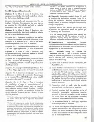
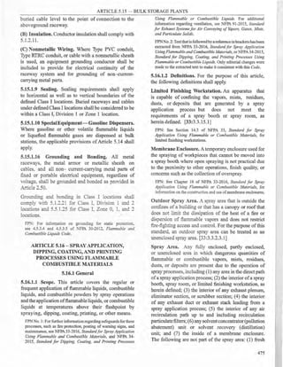
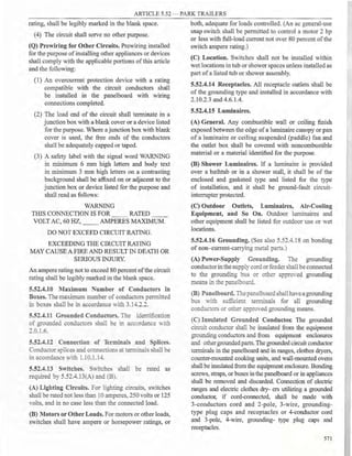
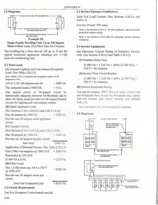
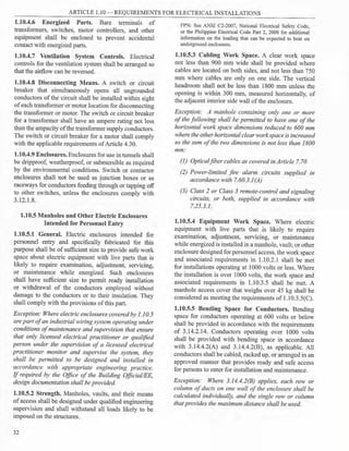
![ARTICLE 1.10 - REQUIREMENTS FOR ELECTRICAL INSTALLATIONS
earth shall be ofconcrete that is not less than 100
mm thick, but where the vault is constructed with
a vacant space or other stories below it, the floor
shall have adequate structural strength for the
load imposed on it and a minimum fire resistance
of 3 hours.
(3) Doors. Each doorway leading into a vault from
the building interior shall be provided with a
tight-fitting door that has a minimum fire rating of
3 hours. It shall be permitted to have such a door
for an exterior wall opening where conditions
warrant.
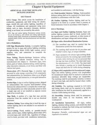
Exception to (]), (2), and (3): Where the vault is
protectedwith automatic sprinkler, water spray, carbon
dioxide, or halon, construction with a ]-hour rating
shall be permitted.
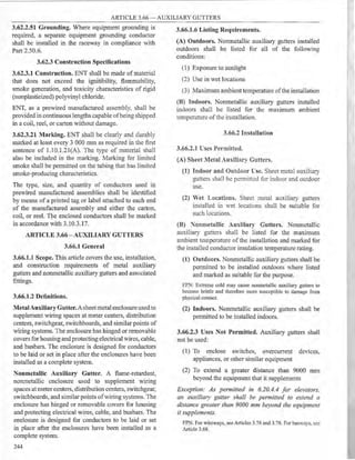
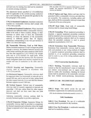
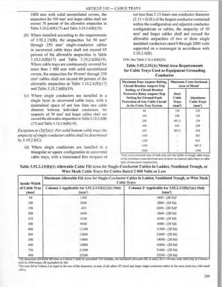
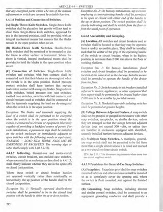
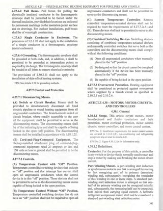
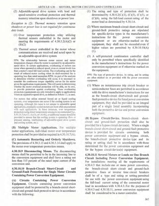
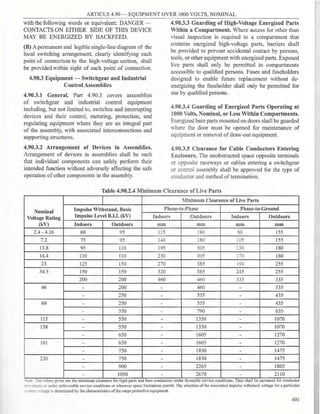
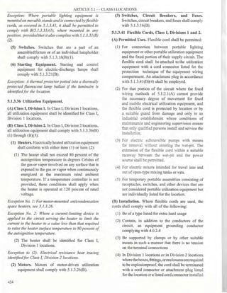
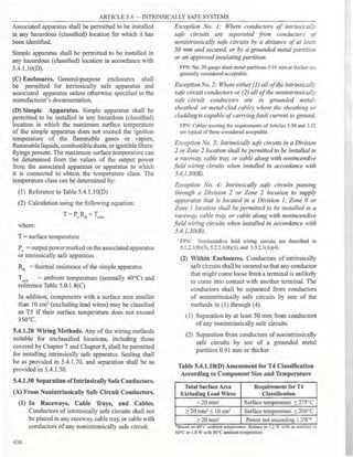
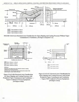
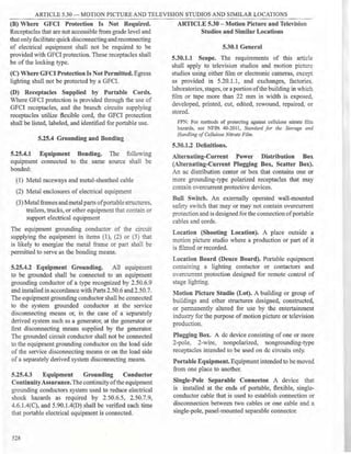
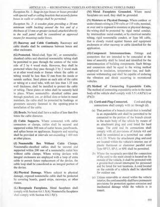
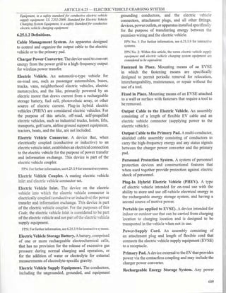
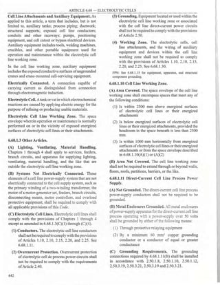
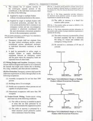
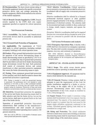
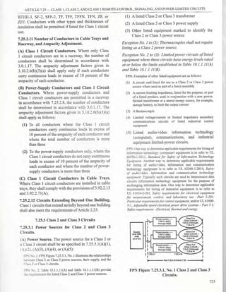
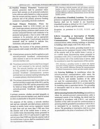
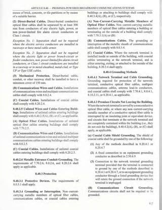
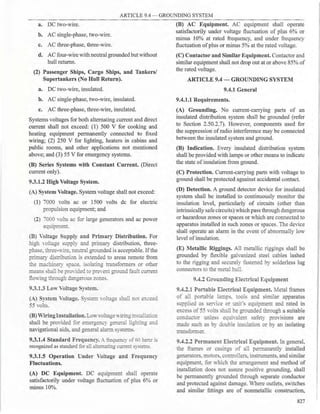
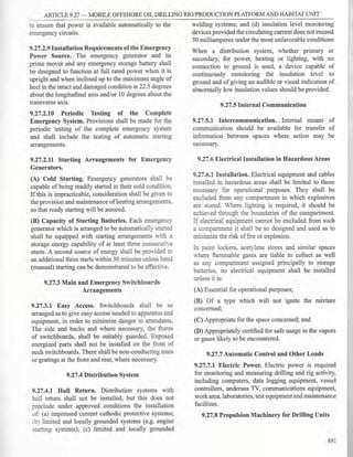
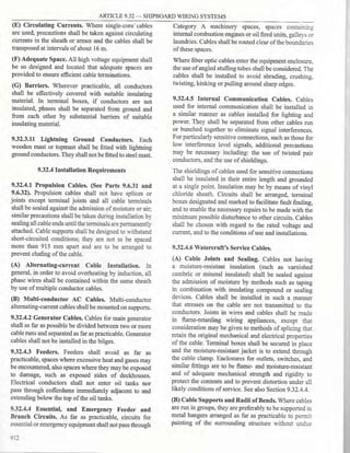
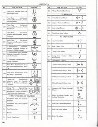
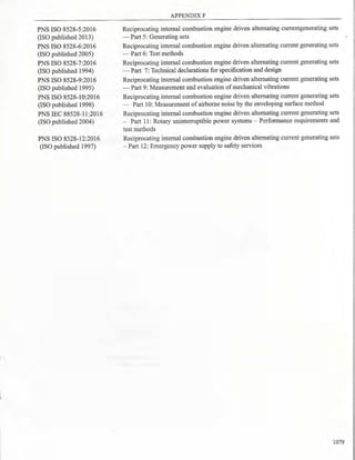
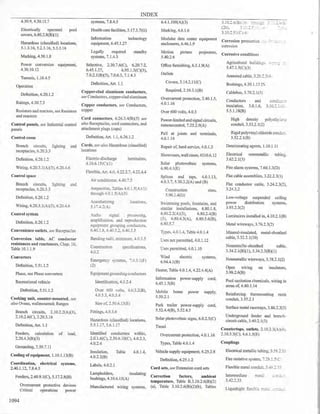
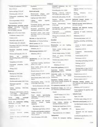
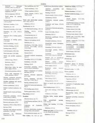
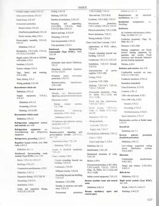
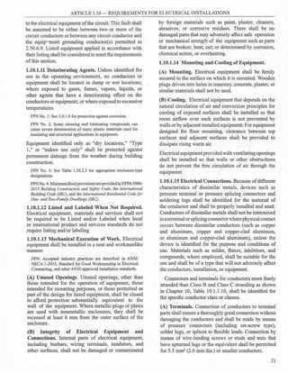
Table 1.10.3.2 Minimum Distance from Fence to
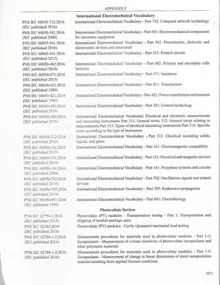
Live Parts
Nominal Voltage
Minimum Distance to
Live Parts (m)
1001 - 13,799 3.05
13,800 - 230,000 4.57
Over 230,000 5.49
Note: For clearances ofconductors for specific system voltages and
typical BIL ratings, see ANSI/IEEE C2-2012, National Electrical
Safety Code.
(4) Locks. Doors shall be equipped with locks, and
doors shall be kept locked, with access allowed
only to qualified persons. Personnel doors shall
swing out and be equipped with panic bars,
pressure plates, or other devices that are normally
latched but that open under simple pressure.
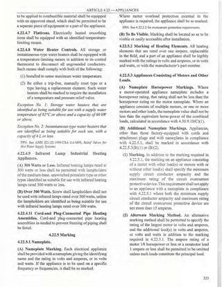
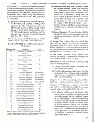
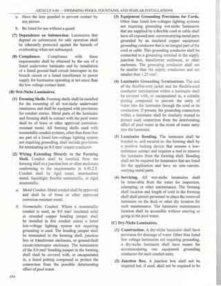
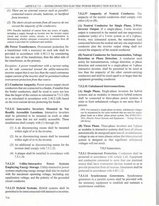
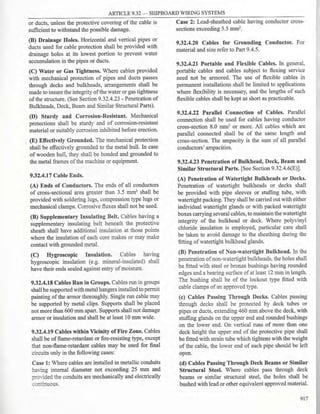
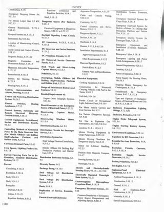
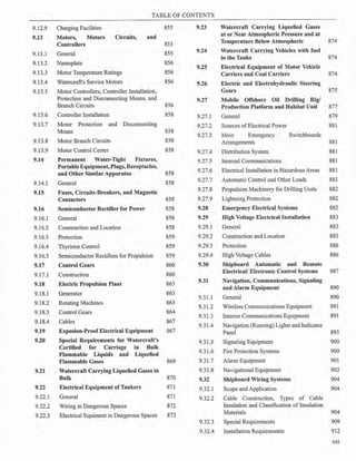
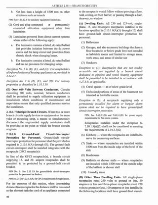
Table 1.10.2.3 Enclosure Selection
For Outdoor Use
Provides a Degree of Protection Against the
Enlosure Type Number
following Environmental Conditions
3 3R 3S 3X 3RX 3SX 4 4X 6 6P
Incidental contact with the enclosed equipment X X X X X X X X X X
Rain X X X X X X X X X X
Windblown dust X - X X - X X X X X
Hosedown - - - - - - X X X X
Corrosive agents - - - X X X - X - X
Temporary submersion - - - - - - - - X X
Prolonged submersion - - - - - - - - - X
For Indoor Use
Provides a Degree of Protection Against the fol-
Enlosure Type Number
lowing Environmental Conditions
2 4 4X 5 6 6P 12 12K 13
1
Incidental contact with the enclosed equipment X X X X X X X X X X
Falling dirt X X X X X X X X X X
Falling liquids and light splashing - X X X X X X X X X
Circulating dust, lint, fibers, and flyings - - X X - X X X X X
Settling airborne dust, lint, fibers, and flyings - - X X X X X X X X
Hosedown amd splashing water - - X X - X X - - -
Oil and coolant seepage - - - - - - - X X X
Oil and coolant spraying and splashing - - - - - - - - - X
Corrosive agents - - - X - - X - - -
Temporary submersion - - - - - X X - - -
Prolonged submersion - - - - - - X - - -
FPN No. l: The term rainti ht is icall used in con·unction with Enclosure T es 3, 3S, 3SX, 3X, 4, 4X, 6, and 6P. The term rainproof is
g typ y J yp
typically used in conjunction with Enclosure Types 3R and 3RX. The term watertight is typically used in conjunction with Enclosure Types 4, 4X,
6, and 6P. The term driptight is typically used in conjunction with Enclosure Types 2, 5, 12, 12K, and 13. The term dusttight is typically used in
conjunction with Enclosure Types 3, 3S, 3SX, 3X, 5, 12, 12K, and 13.
FPN No. 2: Ingress protection (IP) ratings may be found in ANSI/IEC 60529, Degrees ofProtection Provided by Enclosures. IP ratings are not a
substitute for Enclosure Type ratings.
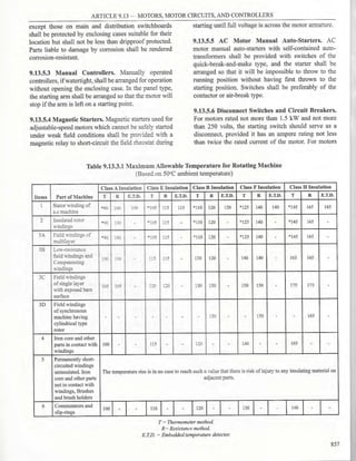
28](https://image.slidesharecdn.com/pec2017part1-241003060423-f7360a96/85/Philllipine-electrical-code-2017-PART-1-pdf-51-320.jpg)


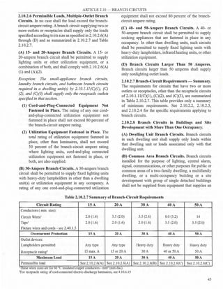


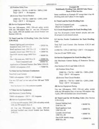
![ARTICLE 2.20 - BRANCH-CIRCUIT, FEEDER AND SERVICE CALCULATIONS
Exception: Where reduced loading of the conductors
resultsfromunits operatingonduty-cycle, intermittently,
orfrom all units not operating at the same time can be
supported by load computations, thefeeder and service
conductors are permitted to have an ampacity less than
I00 percent, provided the conductors have an ampacity
for the load so determined.
2.20.3.13 Small-Appliance and Laundry Loads -
Dwelling Unit.
(A) Small-Appliance Circuit Load. In each dwelling
unit, the load shallbe calculated at1500 volt-amperes for
each2-wiresmall-appliancebranch circuitas coveredby
2.10.1.11(C)(l). Where the load is subdivided through
two or more feeders, the calculated load for each shall
include not less than 1500 volt-amperes for each 2-wire
small-appliance branch circuit. These loads shall be
permitted to be included with the general lighting load
and subjected to the demand factors provided in Table
2.20.3.3.
Exception: The individual branch circuit permitted by
2.I0.3.3(B)(I), Exception No. 2, shall be permitted to
be excludedfrom the calculation required by 2.20.3.13.
(B) Laundry Circuit Load. Aload of not less than 1500
volt-amperes shall be included for each 2-wire laundry
branch circuit installed as covered by 2.10.1. ll(C)
(2). This load shall be permitted to be included with
the general lighting load and subjected to the demand
factors provided in Table 2.20.3.3.
2.20.3.14 Appliance Load-Dwelling Unit(s). It shall
be permissible to apply a demand factor of 75 percent
to the nameplate rating load of four or more appliances
fastened in place, other than electric ranges, clothes
dryers, space-heating equipment, or air-conditioning
equipment, that are served by the same feeder or service
in a one-family, two-family, or multifamily dwelling.
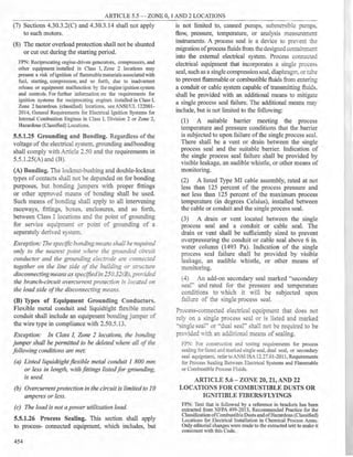
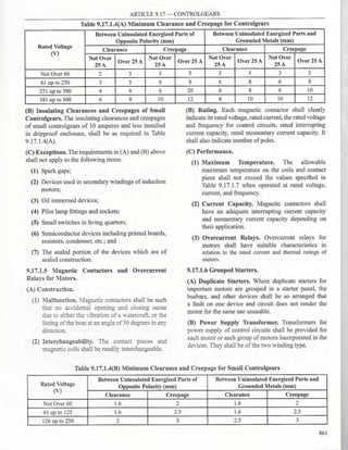
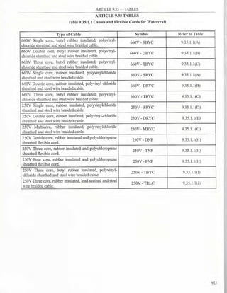
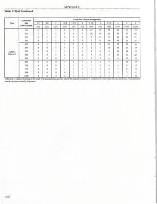
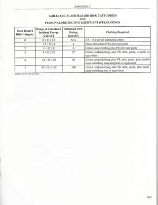
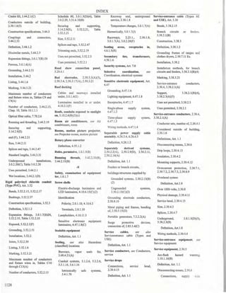
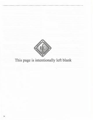
2.20.3.15 Electric Clothes Dryers - Dwelling
Unit(s). The load for household electric clothes dryers
in a dwelling unit(s) shall be either 5000 watts (volt
amperes) or the nameplate rating, whichever is larger,
for each dryer served. The use of the demand factors in
Table 2.20.3.15 shall be permitted. Where two or more
single-phase dryers are supplied by a 3-phase, 4-wire
feeder or service, the total load shall be calculated on
the basis of twice the maximum number connected
between any two phases. Kilovolt-amperes (kVA) shall
be considered equivalent to kilowatts (kW) for loads
calculated in this section.
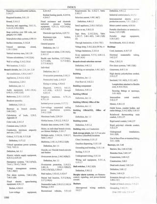
Table 2.20.3.15 Demand Factors for Household
Electric Clothes Dryers
Number of
Demand Factor (%)
Dryers
1-4 100
5 85
6 75
7 65
8 60
9 55
10 50
11 47
12-23 % = 47 - (number ofdryers - 11)
24-42 % = 35 - [0.5 x (number of dryers - 23)]
43 and over 75%
2.20.3.16 Electric Cooking Appliances in Dwelling
Units and Household Cooking Appliances Used
in Instructional Programs. The load for household
electric ranges, wall-mounted ovens, counter-mounted
cooking units, and other household cooking appliances
individually rated in excess of 13
/4 kW shall be
permitted to be calculated in accordance with Table
2.20.3.16. Kilovolt-amperes (kVA) shall be considered
equivalent to kilowatts (kW) for loads calculated under
this section.
Where two or more single-phase ranges are supplied
by a 3-phase, 4-wire feeder or service, the total load
shall be calculated on the basis of twice the maximum
number connected between any two phases.
FPN No. 1: See the examples in Appendix D.
FPN No. 2: See Table 2.20.3.17 for commercial cooking
equipment.
2.20.3.17 Kitchen Equipment - Other Than
Dwelling Unit(s). It shall be permissible to calculate
the load for commercial electric cooking equipment,
dishwasher booster heaters, water heaters, and other
kitchen equipment in accordance with Table 2.20.3.17.
These demand factors shall be applied to all equipment
that has either thermostatic control or intermittent use
as kitchen equipment. These demand factors shall not
apply to space-heating, ventilating, or air-conditioning
equipment.
However, in no case shall the feeder or service
calculated load be less than the sum of the largest two
kitchen equipment loads.
2.20.3.21 Noncoincident Loads. Where it is unlikely
that two or more noncoincident loads will be in use
simultaneously, it shall be permissible to use only
the largest load(s) that will be used at one time for
calculating the total load of a feeder or service.
57](https://image.slidesharecdn.com/pec2017part1-241003060423-f7360a96/85/Philllipine-electrical-code-2017-PART-1-pdf-80-320.jpg)


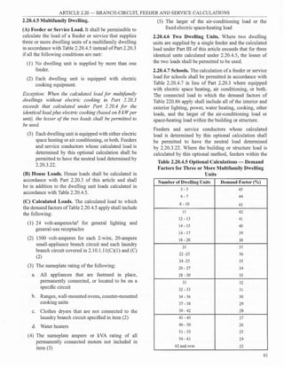


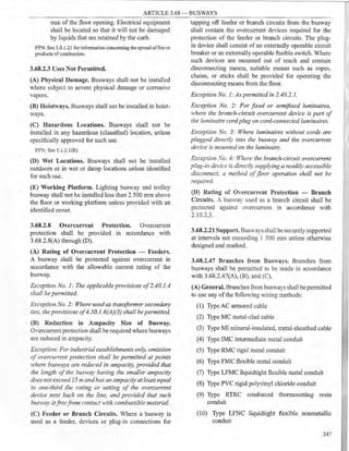
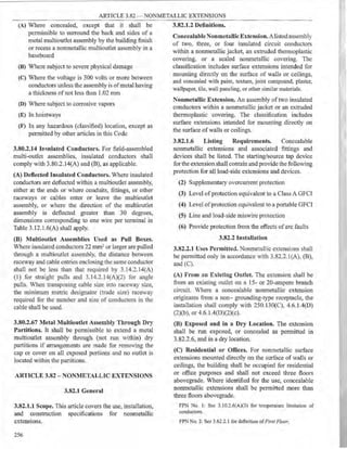
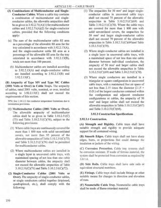
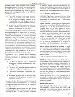
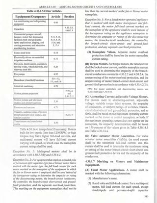
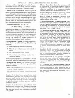
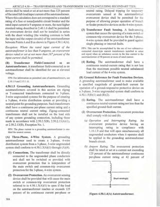
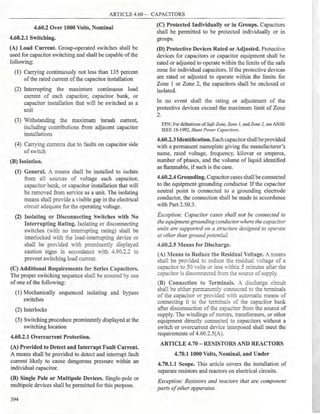
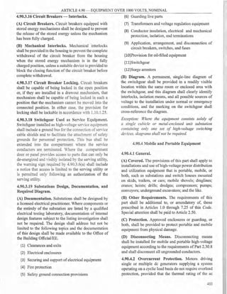
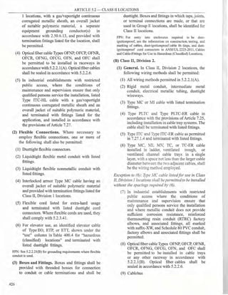
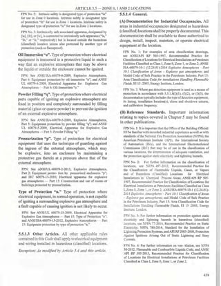
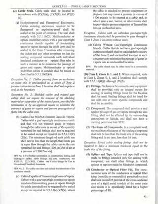
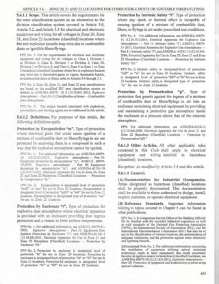
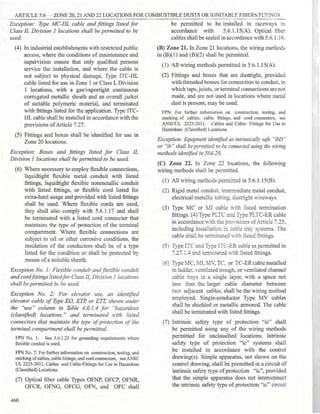
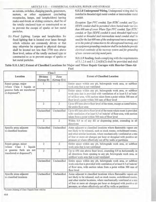
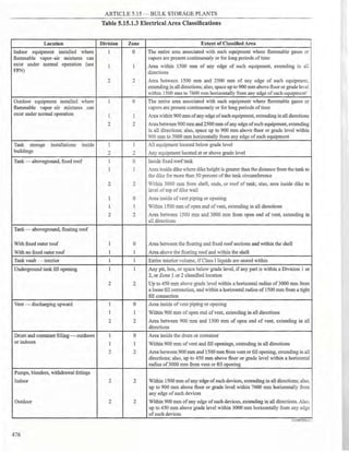
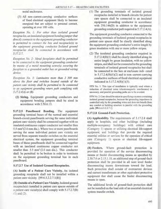
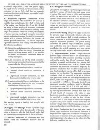
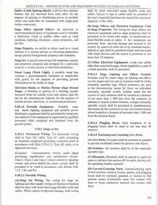
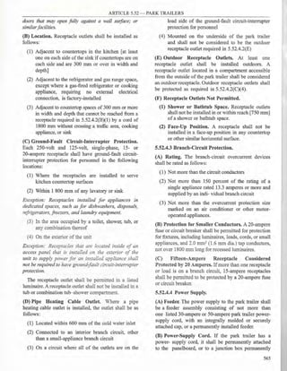
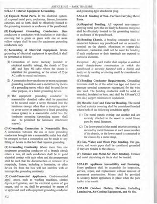
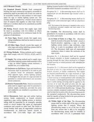
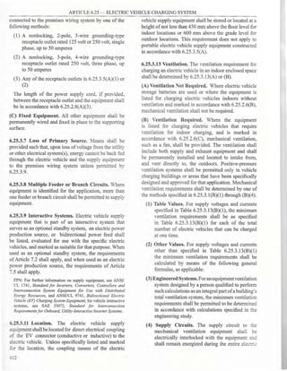
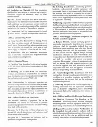
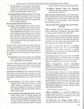
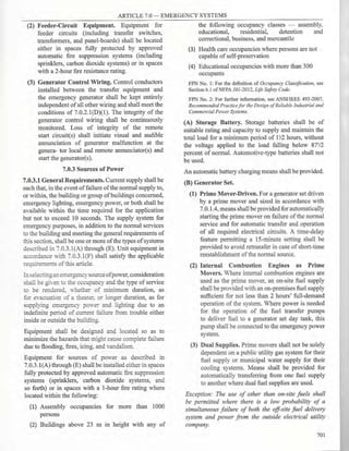
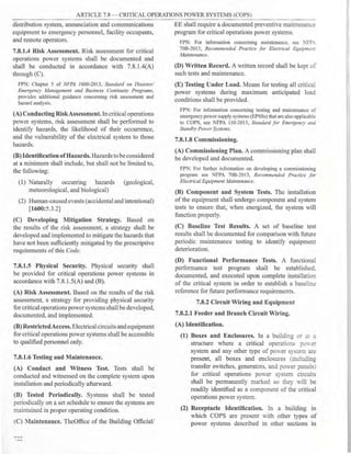
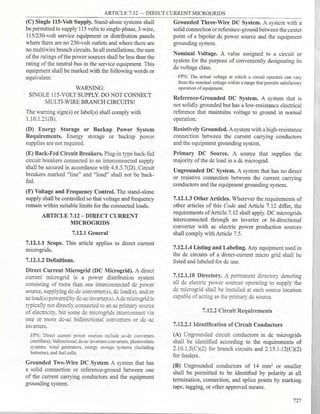
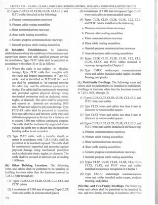
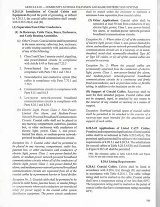
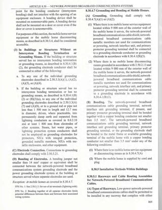
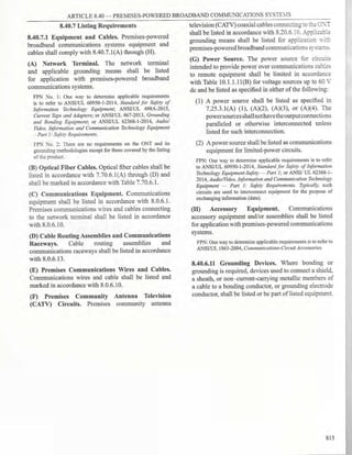
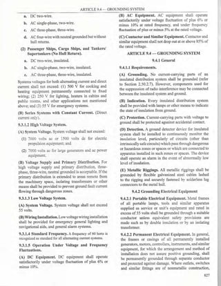
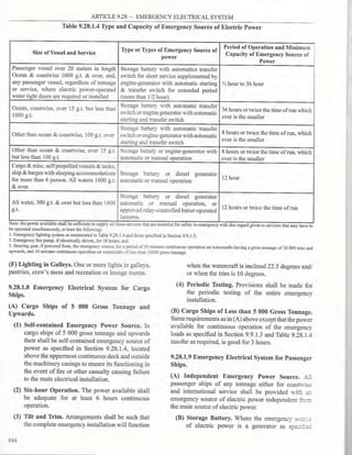
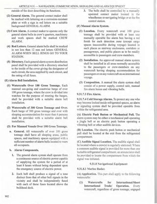
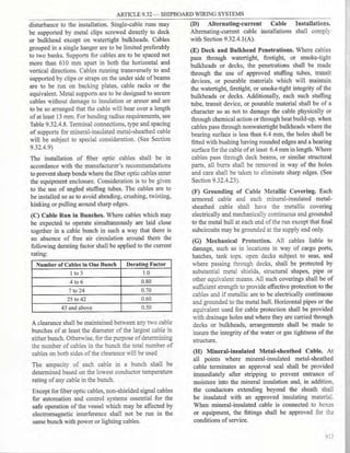
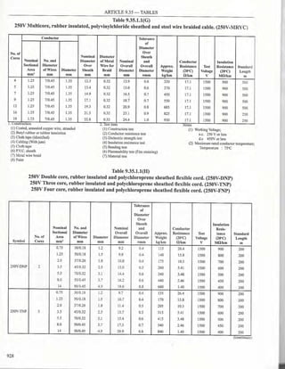
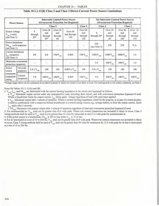
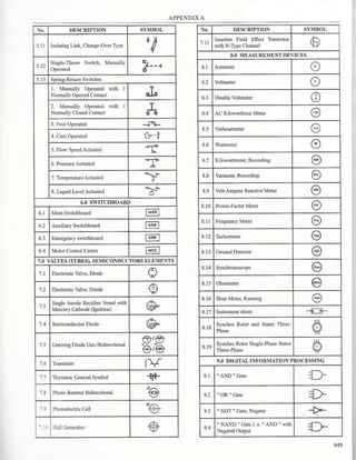
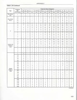
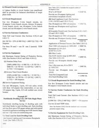
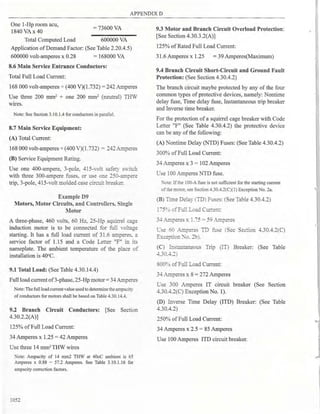
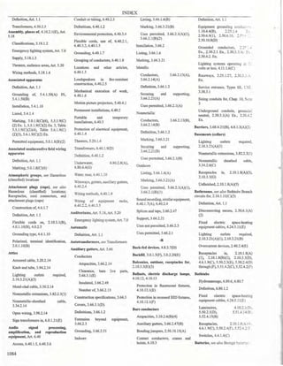
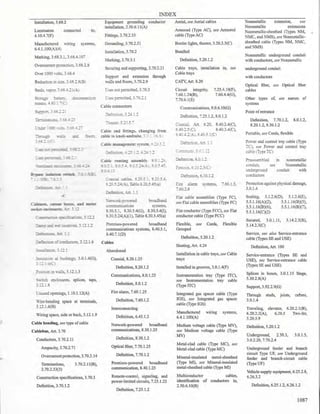
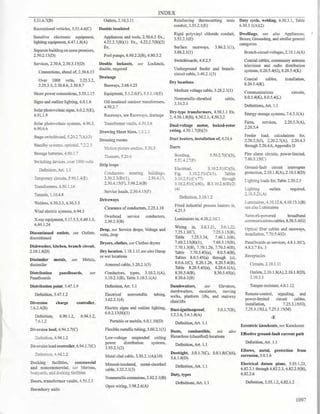
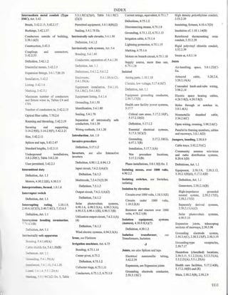
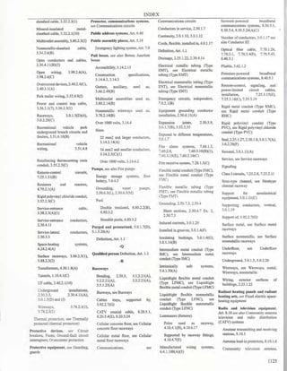
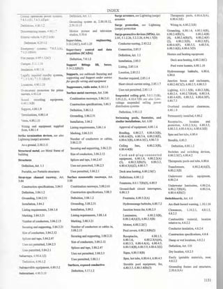
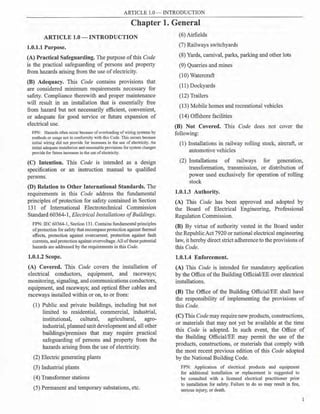
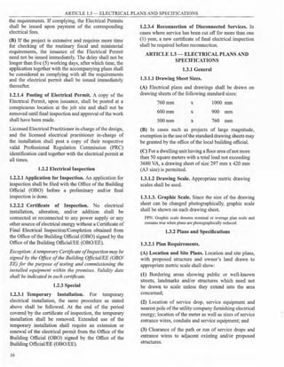
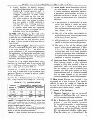
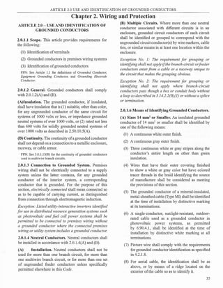
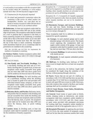
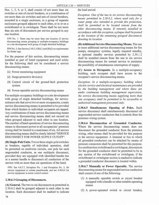
![ARTICLE 2.30 - SERVICES
General
Overhead Service-Drop Conductors
Underg
round Service-Lateral Conductors
Service-Entrance Conductors
Service-Equipment - General
Service-Equipment - Disconnecting Means
Service-Equipment - Overcurrent Protection
Services Exceeding 600 Volts, Nominal
UTILITY COMPANYOVERHEAD
D1S1RIBUTION SYSTEM
UTILITY COMPANY
SERVICE POLE
SERVICE DROP CONDUCTORS
SERVICE PCINT
UTILITY COMPANY
METERING EQUIPMENT
SERVICE PROTECTIVE DEVICE
(WHEN REQUIRED)
[SECTION2.30.6.13 (7)]
SERVICE-ENTRANCE CONDUCTORS
(PART2.30.4]
SERVICE EQUIPMENT r 1
DISCONNECTINGMEANS I I
(PART2.30.6) L J
SERVICE EQUIPMENT
OVERCURRENT PROTECTION
(PART 230.7]
GROUNDINGAND BONDING
[ARTICLE2.50)
BRANCH CIRCUIT
CONDUCTORS ANDFEEDERS
Part 2.30.1
Part 2.30.2
Part 2.30.3
Part 2.30.4
Part 2.30.5
Part 2.30.6
Part 2.30.7
Part 2.30.8
UTILIY COMPANY UNDERGROUND
DISTRIBUTION SYSTEM
UTIUY COMPANY
SERVICE MANHOLE
SERVICE LATERAL
SERVICE POINT
UTILITYCOMPANY
METERING EQUIPMENT
SERVICE PROTECTIVE DEVICE
(WHEN REQUIRED)
(SECTION2 30.613 (7)}
SERVICE-ENTRANCE CONDUCTORS
(PART2.30.4]
SERVICE EQUIPMENT
DISCONNECTING MEANS
[PART2.306]
SERVICE EQUIPMENT
OVERCURRENT PROTECTION
[PART2.307]
GROUNDING AND BONDING
[PART2.50]
BRANCH CIRCUIT
CONDUCTORS��DFEEDERS
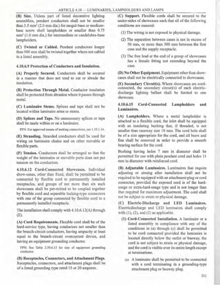
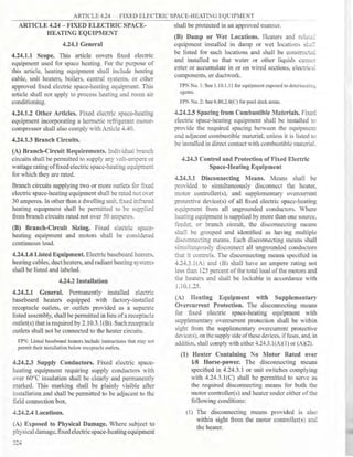
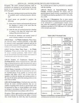
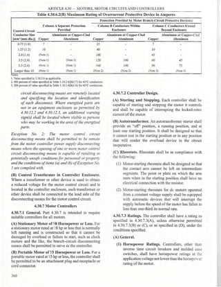
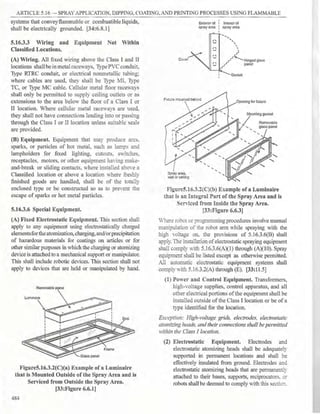
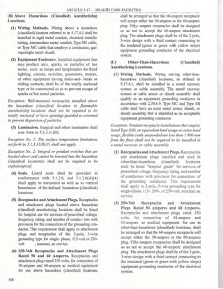
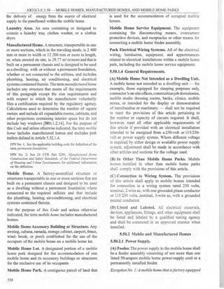
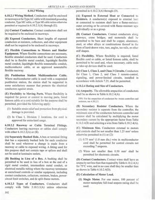
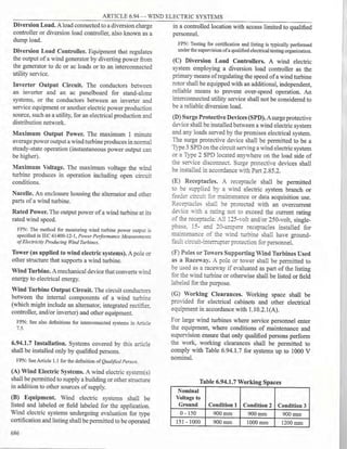
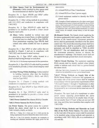
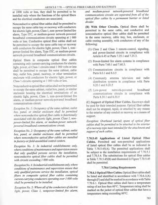
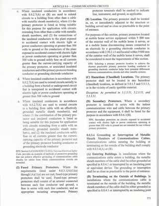
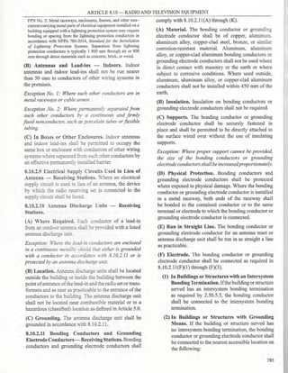
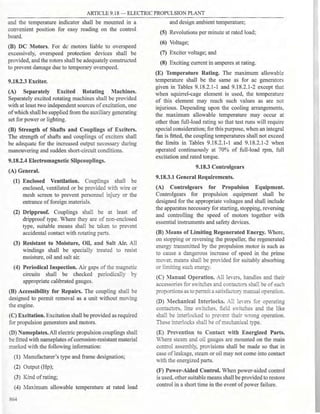
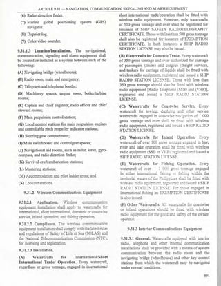
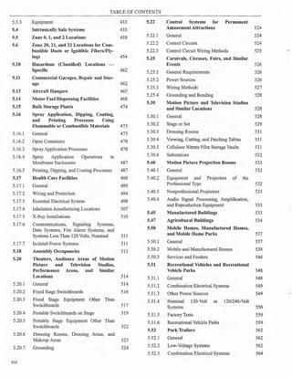
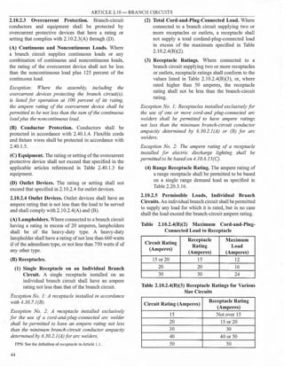
Figure 2.30.1.1 Services.
(6) Systems designed for connection to multiple
sources of supply for the purpose of enhanced
reliability
(B) Special Occupancies. Additional services shall be
permitted for either of the following:
(1) Multiple-occupancy buildings or site
developments with group of single detached
buildings where there is no available space for
service equipment accessible to all occupants
(2) A single building or other structure or a site
development with group of single detached
buildings sufficiently large to make two or more
services necessary
(C) Capacity Requirements. Additional services shall
be permitted under any of the following:
(1) Where the capacity requirements are in excess of
2000 amperes at a supply voltage of 1000 volts
or less
(2) Where the load requirements of a single-phase
installation are greater than the serving agency
normally supplies through one service
(D) Different Characteristics. Additional services
shall be permitted for different voltages, frequencies, or
phases, or for different uses, such as for different rate
schedules.
(E) Identification. Where a building or structure is
supplied by more than one service, or any combination
of branch circuits, feeders, and services, a permanent
plaque or directory shall be installed at each service
disconnect location denoting all other services, feeders,
and branch circuits supplying that building or structure
and the area served by each. See 2.25.2.8.
2.30.1.3 One Building or Other Structure Not to
Be Supplied Through Another. Service conductors
supplying a building or other structure shall not pass
through the interior of another building or other
structure.
2.30.1.6 Conductors Considered Outside the
Building. Conductors shall be considered outside of a
building or other structure under any of the following
conditions:
(1) Where installed under not less than 50 mm of
concrete beneath a building or other structure
(2) Where installed within a building or other
structure in a raceway that is encased in concrete
or brick not less than 50 mm thick
(3) Where installed in any vault that meets the
construction requirements of Part 4.50.3.
(4) Where installed in conduit and under not less
than 450 mm of earth beneath a building or other
structure
(5) Where installed within rigid metal conduit (Type
RMC) or intermediate metal conduit (Type IMC)
used to accommodate the clearance requirements
in 2.30.2.3 and routed directly through an eave
but not a wall of a building.
2.30.1.7 Other Conductors in Raceway or Cable.
Conductors other than service conductors shall not be
installed in the same service raceway or service cable in
which the service conductors are installed.
Exception No. 1: Grounding electrode conductors or
supply side bonding jumpers or conductors shall be
permitted within service raceways.
Exception No. 2: Load management control conductors
having overcurrent protection.
71
T](https://image.slidesharecdn.com/pec2017part1-241003060423-f7360a96/85/Philllipine-electrical-code-2017-PART-1-pdf-94-320.jpg)
![ARTICLE 2.30 - SERVICES
surface only for overhead service conductors
supported on and cabled together with a grounded
bare messenger where the voltage does not exceed
150 volts to ground
(2) 3700 mm - over residential property and
driveways, and those commercial areas not
subject to truck traffic where the voltage does not
exceed 300 volts to ground
(3) 4500 mm - for those areas listed in the 3700-
rnrn classification where the voltage exceeds 300
volts to ground
(4) 5500 mm - over public streets, alleys, roads,
parking areas subject to truck traffic, driveways
on other than residential property, and other land
such as cultivated, grazing, forest, and orchard
(5) 7500 mm over tracks ofrailroads
(C) Clearance from Building Openings. See 2.30.1.9.
(D) Clearance from Swimming Pools. See 6.80.1.8.
(E) Clearance from Communication Wires and
Cables. Clearance from communication wires and
cables shall be in accordance with 8.0.2.1(A)(4).
2.30.2.5 Point ofAttachment. The point ofattachment
of the overhead service conductors to a building or
other structure shall provide the minimum clearances
as specified in 2.30.1.9 and 2.30.2.3. In no case shall
this point ofattachment be less than 3000 mm above
finished grade.
2.30.2.6 Means ofAttachment. Multiconductor cables
used for overhead service conductors shall be attached
to buildings or other structures by fittings identified
for use with service conductors. Open conductors
shall be attached to fittings identified for use with
service conductors or to noncombustible, nonabsorbent
insulators securely attached to the building or other
structure.
2.30.2.7 Service Masts as Supports. Only power
service-drop or overhead service conductors shall be
permitted to be attached to a service mast. Service
masts used for the support ofservice-drop or overhead
service conductors shall be installed in accordance with
2.30.2.7(A) and (B).
(A) Strength. The service mast shall be of adequate
strength or be supported by braces or guys to withstand
safely the strain imposed by the service-drop or
overhead service conductors. Hubs intended for use
with a conduit that serves as a service mast shall be
identified for use with service-entrance equipment.
(B) Attachment. Service-drop or overhead service
conductors shall not be attached to a service mast
between a weatherhead or the end ofthe conduit and a
coupling, where the coupling is located above the last
point ofsecurement to the building or other structure or
is located above the building or other structure.
2.30.2.8 Supports over Buildings. Service conductors
passing over a roof shall be securely supported by
substantial structures. For a grounded system, where
the substantial structure is metal, it shall be bonded
by means of a bonding jumper and listed connector
to the grounded overhead service conductor. Where
practicable, such supports shall be independent ofthe
building.
2.30.3 Underground Service Conductors
2.30.3.1 Installation.
(A) Insulation. Underground service conductors shall
be insulated for the applied voltage.
Exception: A grounded conductor shall be permitted to
be uninsulated as follows:
(]) Bare copper used in a raceway
(2) Bare copper for direct burial where bare copper
is approved for the soil conditions
(3) Bare copper for direct burial without regard to
soil conditions where part of a cable assembly
identifiedfor underground use
(4) Aluminum or copper-clad aluminum without
individual insulation or covering where part of a
cable assembly identifiedfor underground use in
a raceway orfor direct burial
(B) Wiring Methods. Underground service conductors
shall be installed in accordance with the applicable
requirements ofthis Code covering the type ofwiring
method used and shall be limited to the following
methods:
(1) Type RMC conduit
(2) Type IMC conduit
(3) Type NUCC conduit
(4) Type HDPE conduit
(5) Type PVC conduit
(6) Type RTRC conduit
(7) Type IGS cable
(8) Type USE conductors or cables
(9) Type MV or Type MC cableidentified for direct
burial applications
73](https://image.slidesharecdn.com/pec2017part1-241003060423-f7360a96/85/Philllipine-electrical-code-2017-PART-1-pdf-96-320.jpg)


![ARTICLE 2.40 - OVERCURRENT PROTECTION
(4) 3-Wire Direct-Current Circuits. Individual
single-pole circuit breakers rated 125/250 volts
de with identified handle ties shall be permitted
as the protection for each ungrounded conductor
for line-to-line connected loads for 3-wire, direct
current circuits supplied from a system with a
grounded neutral where the voltage to ground
does not exceed 125 volts.s
2.40.2. Location
2.40.2.1 Location in Circuit. Overcurrent protection
shall be provided in each ungrounded circuit conductor
and shall be located at the point where the conductors
receive their supply except as specified in 2.40.2.l(A)
through (H). Conductors supplied under the provisions
of 2.40.2.l(A) through (H) shall not supply another
conductor except through an overcurrent protective
device meeting the requirements of 2.40.1.4.
(A) Branch-Circuit Conductors. Branch-circuit
tap conductors meeting the requirements specified
in 2.10.2.2 shall be permitted to have overcurrent
protection as specified in 2.10.2.3.
(B) Feeder Taps. Conductors shall be permitted to be
tapped, without overcurrent protection at the tap, to a
feeder as specified in 2.40.2.l(B)(l ) through (B)(5).
The provisions of 2.40.1.4(B) shall not be permitted for
tap conductors.
(1) Taps Not over 3000 mm Long. If the length of the
tap conductors does not exceed 3000 mm and the
tap conductors comply with all of the following:
(1) The ampacity of the tap conductors is
a. Not less than the combined calculated loads
on the circuits supplied by the tap conductors,
and
b. Not less than the rating of the equipment
containing an overcurrent device(s) supplied
by the tap conductors or not less than the
rating of the overcurrent protective device at
the termination of the tap conductors.
Exception to b: Where listed equipment, such as a surge
protective device(s) [SPD(s)], is provided with specific
instructions on minimum conductor sizing, the ampacity
ofthe tap conductors supplying that equipment shall be
permitted to be determined based on the manufacturers
instructions.
(2) The tap conductors do not extend beyond
the switchboard, switchgear, panelboard,
disconnecting means, or control devices they
supply.
(3) Except at the point of connection to the feeder,
the tap conductors are enclosed in a raceway,
which extends from the tap to the enclosure
of an enclosed switchboard, switchgear, a
panelboard, or control devices, or to the back
of an open switchboard.
(4) For field installations, ifthetap conductors leave
the enclosure or vault in which the tap is made,
the ampacity of the tap conductors is not less
than one-tenth of the rating of the overcurrent
device protecting the feeder conductors.
FPN: For overcurrent protection requirements for panelboards,
see 4.8.3.7.
(2) Taps Not over 7500 mm Long. Where the length
of the tap conductors does not exceed 7500
mm and the tap conductors comply with all the
following:
(1) The ampacity of the tap conductors is not less
than one-third of the rating of the overcurrent
device protecting the feeder conductors.
(2) The tap conductors terminate in a single circuit
breaker or a single set of fuses that limit the
load to the ampacity of the tap conductors. This
device shall be permitted to supply any number
of additional overcurrent devices on its load
side.
(3) The tap conductors are protected from physical
damage by being enclosed in an approved
raceway or by other approved means.
(3) Taps Supplying a Transformer [Primary Plus
Secondary Not over 7500 mm Long]. Where the
tap conductors supply a transformer and comply
with all the following conditions:
(1) The conductors supplying the primary of a
transformer have an ampacity at least one-third
the rating of the overcurrent device protecting
the feeder conductors.
(2) Theconductors supplied by thesecondary ofthe
transformer shall have an ampacity that is not
less than the value of the primary-to-secondary
voltage ratio multiplied by one-third of the
rating of the overcurrent device protecting the
feeder conductors.
(3) The total length of one primary plus one
secondary conductor, excluding any portion of
the primary conductor that is protected at its
ampacity, is not over 7500 mm.
(4) The primary and secondary conductors are
protected from physical damage by being
87](https://image.slidesharecdn.com/pec2017part1-241003060423-f7360a96/85/Philllipine-electrical-code-2017-PART-1-pdf-110-320.jpg)
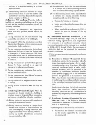


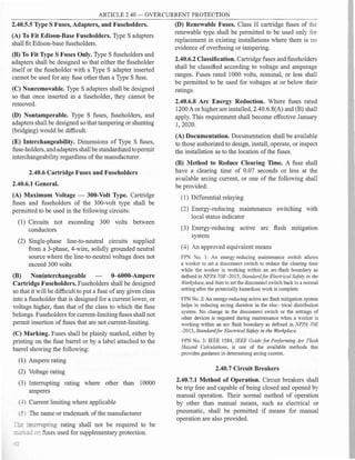

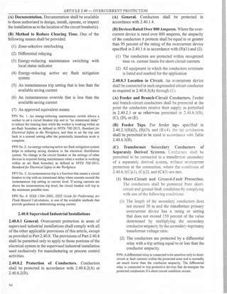
![ARTICLE 2.40 - OVERCURRENT PROTECTION
Table 2.40.8.3(B) Tap Conductor Short-Circuit
Current Ratings.
Tap conductors are considered to be protected under short-circuit
conditions when their short-circuit temperature limit is not
exceeded. Conductor heating under short-circuit conditions is
determined by (1) or (2):
(1) Short-CircuitFormulafor Copper Conductors
(12
/A 2
)t = 0.0297 log10 [(T2 + 234)/(T 1 + 234)]
(2) Short-Circuit Formula/or Aluminum Conductors
(12
/A 2)t = 0.0125 log10
[(T2
+ 228)/(T 1
+ 228)]
where:
I= short-circuit current in amperes A = conductor area in circular
mils. (Note: 1 circular mil= 5.067 x 104 mm2
)
t= time ofshort circuit in seconds (for times less than or equal to
10 seconds)
T 1
= initial conductor temperature in degrees Celsius
T2
=final conductor temperature in degrees Celsius
Copper conductor with paper, rubber, varnished cloth insulation,
Copper conductor with thermoplastic insulation, T2
= 150 Copper
conductor with cross-linked polyethylene insulation,
T,=250
Copper conductor with ethylene propylene rubber insulation,
T, = 250
Aluminum conductor with paper, rubber, varnished cloth insula
tion. T, = 200
X:.ccinun:: conductor ;th thermoplastic insulation. T 2
= 150
..!�::= cor:cuc�L� ;th cross-linked polyethylene insulation,
X=:::= co::c::c:o�v.:::: e:::i� '.e::ep�opyler:erubber insulation.
(3 l T:::e conciuc:ors sha[ be considered tO
be pro.:ec:ed :: cac�atio:is. made unde:
engine-ering supenision. dererm::ne iliar the
�--:em OYercmrem deices "-ill protec� the
conductors ithin recognized rime -S. current
limits for all short-circuit and ground-fault
conditions.
(2) 0Yerload Protection. The conductors shall
be protected against overload conditions by
complying with one of the following:
(1) Theconductors terminate in asingleovercurrent
device that will limit the load to the conductor
ampacity.
(2) The sum of the overcurrent devices at the
conductor termination limits the load to the
conductor ampacity. The overcurrent devices
shall consist of not more than six circuit
breakers or sets of fuses mounted in a single
enclosure, in a group of separate enclosures,
or in or on a switchboard or switchgear. There
shall be no more than six overcurrent devices
grouped in any one location.
(3) Overcurrent relaying is connected [with a
current transformer(s), if needed] to sense all
of the secondary conductor current and limit
the load to the conductor ampacity by opening
upstream or downstream devices.
(4) Conductors shall be considered to be protected
if calculations, made under engineering
superv1s1on, determine that the system
overcurrent devices will protect the conductors
from overload conditions.
(3) Physical Protection. The secondary conductors
are protected from physical damage by being
enclosed in an approYed raceway or by other
approved means.
(D) Outside Feeder Taps. Outside conductors shall be
permitted to be tapped to a feeder or to be connected at
a transformer secondary. without oYercurrentprotection
at the tap or connection, Yhere all the following
conditions are met:
( 1) The conductors are protected from physical
damage in an approYed manner.
(2) The sum of the overcurrent devices at the
conductor termination limits the load to the
conductor ampacity. The overcurrent devices
shall consist ofnot more than six circuit breakers
or sets of fuses mounted in a single enclosure,
in a group of separate enclosures, or in or on a
switchboard or switchgear. There shall be no
more than six overcurrent devices grouped in any
one location.
(3) The tap conductors are installed outdoors of a
building or structure except at the point of load
termination.
(4) The overcurrent device for the conductors is an
integral part ofa disconnecting means or shall be
located immediately adjacent thereto.
(5) The disconnecting means for the conductors
are installed at a readily accessible location
complying with one ofthe following:
a. Outside ofa building or structure
b. Inside, nearest the point of entrance of the
conductors
95
T. =.::-0
T. = 250](https://image.slidesharecdn.com/pec2017part1-241003060423-f7360a96/85/Philllipine-electrical-code-2017-PART-1-pdf-118-320.jpg)


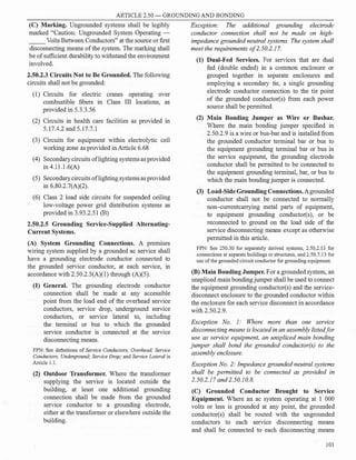


![ARTICLE 2.50 - GROUNDING AND BONDING
(a) A supply-side bonding jumper ofthe wire type
shall comply with 2.50.5.13(C), based on the
size ofthe derived ungrounded conductors.
(b) A supply-side bonding jumper of the bus type
shall have a cross-sectional area not smaller
than a supply-side bonding jumper of the wire
type as determined in 2.50.5.13(Cj.-
Exception: A supply-side bondingjumper shall not be
required between enclosures for installations made in
compliance with 2.50.2.11(A)(]), Exception No. 2.
(3) Grounded Conductor. If a grounded conductor
is installed and the system bonding jumper
connection is not located at the source,
2.50.2.11(A)(3)(a) through (A)(3)(d) shall apply.
(a) Sizing for a Single Raceway. The grounded
conductor shall not be smaller than specified in
Table 2.50.5.13(C)(l) .
(b) Parallel Conductors in Two or More Raceways.
If the ungrounded conductors are installed in
parallel in two or more raceways, the grounded
conductor shall also be installed in parallel. The
size ofthe grounded conductor in each raceway
shall be based on the total area in square
millimeter of the parallel derived ungrounded
conductors in the raceway as indicated in
2.50.2.ll(A)(3)(a), but not smaller than 50
mrn2
.
FPN: See 3.10.2.l(H) for grounded conductors connected in
parallel.
(c) Delta-Connected System. The grounded
conductor of a 3-phase, 3-wire delta system
shall have an ampacity not less than that of the
ungrounded conductors.
(d) Impedance Grounded System. The grounded
conductor of an impedance grounded neutral
system shall be installed in accordance with
2.50.2.17 or 2.50.10.8, as applicable.
(4) Grounding Electrode. The building or structure
grounding electrode system shall be used as the
grounding electrode for the separately derived
system. If located outdoors, the grounding
electrode shall beinaccordancewith 2.50.2.11(C).
Exception: Ifa separately derived system originates in
equipment that is listed and identified as suitable for
use as service equipment, the grounding electrode used
for the service or feeder equipment shall be permitted
to be used as the grounding electrode for the separately
derived system.
104
FPN No. 1: See 2.50.5.15(D) for bonding requirements for
interior metal water piping in the area served by separately
derived systems.
FPN No. 2: See 2.50.3.1 and 2.50.3.9 for requirements for
bonding all electrodes together iflocated at the same building or
structure.
(5) Grounding Electrode Conductor, Single
Separately Derived System. A grounding
electrode conductor for a single separately
derived system shall be sized in accordance with
2.50.3.17 for the derived ungrounded conductors.
It shall be used to connect the grounded
conductor ofthe derived system to the grounding
electrode in accordance with 2.50.2.11(A)(4),
or as permitted in 2.50.3.19(C)(l) and (2). This
connection shall be made at the same point on
the separately derived system where the system
bonding jumper is connected.
Exception No. I: Ifthe system bondingjumper specified
in 2.50.2.ll(A)(I) is a wire or busbar, it shall be
permitted to connect the grounding electrode conductor
to the equipment grounding terminal, bar, or bus if
the equipment grounding terminal, bar, or bus is of
sufficient size for the separately derived system.
Exception No. 2: Ifthe source of a separately derived
system is located within equipment listed and identified
as suitable for use as service equipment, the grounding
electrode conductor from the service or feeder
equipment to the grounding electrode shall be permitted
as the grounding electrode conductor for the separately
derived system, provided that the grounding electrode
conductor is of sufficient size for the separately derived
system. Ifthe equipment grounding bus internal to the
equipment is not smaller than the required grounding
electrode conductor for the separately derived system,
the grounding electrode connection for the separately
derived system shall be permitted to be made to the bus.
Exception No. 3: A grounding electrode conductor
shall not be required for a system that supplies a Class
I, Class 2, or Class 3 circuit and is derived from a
transformer rated not more than I000 volt-amperes,
provided the grounded conductor is bonded to the
transformer frame or enclosure by a jumper sized in
accordance with 2.50.2.ll(A)(I), Exception No. 3, and
the transformer frame or enclosure is grounded by one
of the means specified in 2.50. 7.5.
(6) Grounding Electrode Conductor, Multiple
Separately Derived Systems. A common
grounding electrode conductor for multiple
separately derived systems shall be permitted.
If installed, the common grounding electrode](https://image.slidesharecdn.com/pec2017part1-241003060423-f7360a96/85/Philllipine-electrical-code-2017-PART-1-pdf-127-320.jpg)
![ARTICLE 2.50 - GROUNDING AND BONDING
conductor shall be used to connect the grounded
conductor ofthe separately derived systems to the
grounding electrode as specified in 2.50.2.l l(A)
(4).Agroundingelectrode conductortap shallthen
be installed from each separately derived system
to the common grounding electrode conductor.
Each tap conductor shall connect the grounded
conductor of the separately derived system to
the common grounding electrode conductor. This
connection shall be made at the same point on
the separately derived system where the system
bondingjumper is connected.
Exception No. 1: Ifthe system bondingjumper specified
in 2.50.2.11(A)(]) is a wire or busbar, it shall be
permitted to connect the grounding electrode conductor
tap to the equipment grounding terminal, bar, or bus,
provided the equipment grounding terminal, bar, or bus
is of sufficient sizefor the separately derived system.
Exception No. 2: A grounding electrode conductor
shall not be requiredfor a system that supplies a Class
1, Class 2, or Class 3 circuit and is derived from a
transformer rated not more than 1 000 volt-amperes,
provided the system grounded conductor is bonded to
the transformerframe or enclosure by ajumper sized in
accordance with 2.50.2.ll(A)(l), Exception No. 3, and
the transformer frame or enclosure is grounded by one
of the means specified in 2.50. 7.5.
(a) Common Grounding Electrode Conductor. The
common grounding electrode conductor shall
be permitted to be one of the following:
(1) A conductor ofthe wire type not smaller than
80 mm2
copper or 125 mm2
aluminum
(2) A metal water pipe that complies with
2.50.3.19(C)(l )
(3) The metal structural frame of the building or
structure that complies with 2.50.3.l9(A)(2)
or is connected to the grounding electrode
system by a conductor that not smaller than
80 mm2
copper or 125 mm2
aluminum
(b) Tap Conductor Size. Each tap conductor shall
be sized in accordance with 2.50.3.17 based
on the derived ungrounded conductors of the
separately derived system it serves.
Exception: If the source of a separately derived
system is located within equipment listed and
identified as suitable for use as service equipment,
the grounding electrode conductor from the service
or feeder equipment to the grounding electrode shall
be permitted as the grounding electrode conductor
for the separately derived system, provided that the
grounding electrode conductor is of sufficient size
for the separately derived system. If the equipment
grounding bus internal to the equipment is not smaller
than the required grounding electrode conductor for
the separately derived system, the grounding electrode
connection for the separately derived system shall be
permitted to be made to the bus.
(c) Connections. All tap connections to the
common grounding electrode conductor shall
be made at an accessible location by one of the
following methods:
(1) A connector listed as grounding and bonding
equipment.
(2) Listed connections to aluminum or copper
busbars not smaller than 6 mm thick x 50 mm
wide and ofsufficient length to accommodate
the number of terminations necessary for
the installation. If aluminum busbars are
used, the installation shall also comply with
2.50.3.l S(A).
(3) The exothermic welding process.
Tapconductors shall be connected to the common
grounding electrode conductor in such a manner
that the common grounding electrode conductor
remains without a splice or joint.
(7) Installation. The installation of all grounding
electrode conductors shall comply with
2.50.3.15(A), (B), (C), and (E).
(8) Bonding. Structural steel and metal piping shall
be connected to the grounded conductor of a
separately derived system in accordance with
2.50.5.15(D).
(B) Ungrounded Systems. The equipment of an
ungrounded separately derived system shall be
grounded and bonded as specified in 2.50.2.ll(B)(l)
through (B)(3).
(1) Grounding Electrode Conductor. A grounding
electrode conductor, sized in accordance with
2.50.3.17 for the largest derived ungrounded
conductor (s) or set of derived ungrounded
conductors, shall be used to connect the metal
enclosures ofthe derived system to the grounding
electrode as specified in 2.50.2.1l(A)(5) or (6), as
applicable. This connection shall be made at any
point on the separately derived system from the
source to the first system disconnecting means.
If the source is located outside the building
or structure supplied, a grounding electrode
105](https://image.slidesharecdn.com/pec2017part1-241003060423-f7360a96/85/Philllipine-electrical-code-2017-PART-1-pdf-128-320.jpg)


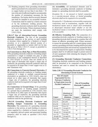
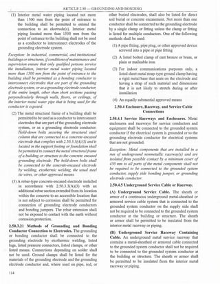
![ARTICLE 2.50 - GROUNDING AND BONDING
2.50.4.7 Other Conductor Enclosures and Raceways.
Except as permitted by 2.50.6.3(I), metal enclosures
and raceways for other than service conductors shall be
connected to the equipment grounding conductor.
Exception No. 1: Metal enclosures and raceways for
conductors added to existing installations ofopen wire,
knoband-tube wiring, and nonmetallic-sheathed cable
shall not be required to be connected to the equipment
grounding conductor where these enclosures or wiring
methods comply with (]) through (4) asfollows:
(1) Do notprovide an equipment ground
(2) Are in runs ofless than 7500 mm
(3) Are free from probable contact with ground,
grounded metal, metal lath, or other conductive
material
(4) Are guarded against contact by persons
Exception No. 2: Short sections ofmetal enclosures or
raceways usedto provide support orprotection ofcable
assemblies from physical damage shall not be required
to be connected to the equipment grounding conductor.
Exception No. 3: Metal components shall not be
required to be connected to the equipment grounding
conductor or supply-side bondingjumper where either
ofthefollowing conditions exist:
(]) The metal components are installed in a run
of nonmetallic raceway(s) and isolated from
possible contact by a minimum cover of450 mm
to any part ofthe metal components.
(2) The metal components are part ofan installation
of nonmetallic raceway(s) and are isolated
from possible contact to any part of the metal
components by being encased in not less than 50
mm ofconcrete.
2.50.5 Bonding
2.50.5.1 General. Bonding shall be provided where
necessary to ensure electrical continuity and the
capacity to conduct safely any fault current likely to be
imposed.
2.50.5.3 Services.
(A) Bonding ofEquipment for Services. The normally
non- current-carrying metal parts ofequipmentindicated
in 2.50.5.3(A)(l) and (A)(2) shall be bonded together.
(1) All raceways, cable trays, cablebus framework,
auxiliary gutters, or service cable armor or
sheath that enclose, contain, or support service
conductors, except as permitted in 2.50.4.1
(2) All enclosures containing service conductors,
including meter fittings, boxes, or the like,
interposed in the service raceway or armor
(B) Method of Bonding at the Service. Bonding
jumpers meeting the requirements of this article
shall be used around impaired connections, such as
reducing washers or oversized, concentric, or eccentric
knockouts. Standard locknuts or bushings shall not
be the only means for the bonding required by this
section but shall be permitted to be installed to make a
mechanical connection ofthe raceway(s).
Electrical continuity at service equipment, service
raceways, and service conductor enclosures shall be
ensured by one ofthe following methods:
(1) Bonding equipment to the grounded service
conductor in a manner provided in 2.50.1.8
(2) Connections utilizing threaded couplings
or threaded hubs on enclosures if made up
wrenchtight
(3) Threadless couplings and connectors if made up
tight for metal raceways and metal-clad cables
(4) Other listed devices, such as bonding-type
locknuts, bushings, or bushings with bonding
jumpers
2.50.5.5 Bonding for Communication Systems.
Communications system bonding terminations shall be
connected in accordance with (A) or (B).
(A) TheIntersystem BondingTerminationDevice.An
intersystem bonding termination (IBT)for connecting
intersystem bonding conductors shall be provided
external to enclosures at the service equipment or
metering equipment enclosure and at the disconnecting
means for any additional buildings or structures. If an
IBT is used, it shall comply with the following:
(1) Be accessible for connection and inspection.
(2) Consist of a set of terminals with the capacity
for connection of not less than three intersystem
bonding conductors.
(3) Not interfere with opening the enclosure for
a service, building or structure disconnecting
means, or metering equipment.
(4) At the service equipment, be securely mounted
and electrically connected to an enclosure for the
service equipment, to the meter enclosure, or to
an exposed nonflexible metallic service raceway,
or be mounted at one of these enclosures and be
connected to the enclosure or to the grounding
electrode conductor with a minimum 14 mm2
copper conductor
115](https://image.slidesharecdn.com/pec2017part1-241003060423-f7360a96/85/Philllipine-electrical-code-2017-PART-1-pdf-138-320.jpg)
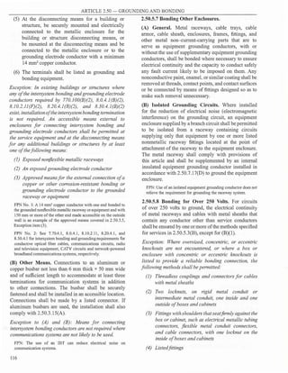


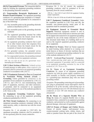


![ARTICLE 2.50 - GROUNDING AND BONDING
shall not be required to be larger than the largest
ungrounded service-entrance conductor(s).
(2) Parallel Conductors in Two or More Raceways
or Overhead Conductors. If the ungrounded
service-entrance conductors are installed in
parallel in two or more raceways or as overhead
parallel conductors, the grounded conductors
shall also be installed in parallel. The size of the
grounded conductor in each raceway or overhead
shall be based on the total cross-sectional area
of the parallel un-grounded conductors in the
raceway or overhead, as indicated in 2.50.10.7(A)
(1), but not smaller than 50 mm]
.
FPN: See 3.10.2.l(H) for grounded conductors connected in
parallel.
(3) Delta-Connected Service. The grounded
conductor of a 3-phase, 3-wire delta service
shall have an ampacity not less than that of the
ungrounded conductors.
(4) Impedance Grounded :"eutral Systems.
Impedance grounded neuual systems shall be
installed in accordance with 2.50.10.8.
(B) Systems Without a Grounded Conductor at the
Service Point. Where an ac system is grounded at any
point and is not provided with a grounded conductor at
the service point, a supply-side bonding jumper shall
be installed and routed with the ungrounded conductors
to each service disconnecting means and shall be
connected to each disconnecting means equipment
grounding conductor terminal or bus. The supply-side
bonding jumper shall be installed in accordance with
2.50.10.7(B)(l) through (B)(3).
Exception: Where two or more service disconnecting
means are located in a single assemb�v listedfor use as
service equipment, it shall be permitted to connect the
supply-side bonding jumper to the assembly common
equipment grounding terminal or bus.
(1) Sizing for a Single Raceway or Overhead
Conductor. The supply-side bonding jumper
shall not be smaller than the required grounding
electrode conductor specified in Table
2.50.5.13(C)(l) but shall not be required to
be larger than the largest ungrounded service
entrance conductor(s).
(2) Parallel Conductors in Two or More Raceways
or Overhead Conductors. If the ungrounded
service-entrance conductors are installed in
parallel in two or more raceways or overhead
conductors, the supply-side bondingjumper shall
also be installed in parallel. The size ofthe supply-
132
side bondingjumper in each raceway or overhead
shall be based on the total cross-sectional area of
theparallelungrounded conductors inthe raceway
or overhead, as indicated in 2.50.10.7(A)(l), but
not smaller than 50 mm2
•
(3) Impedance Grounded Neutral Systems.
Impedance grounded neutral systems shall be
installed in accordance with 2.50.10.8.
2.50.10.8 Impedance Grounded Neutral Systems.
Impedance grounded neutral systems in which a
grounding impedance, usually a resistor, limits the
ground-fa�lt current shall be permitted where all of the
following conditions are met:
(1) The conditions of maintenance and supervision
ensure that only qualified persons service the
installation.
(2) Ground detectors are installed on the system.
(3) Line-to-neutral loads are not served.
Impedance grounded neutral systems shall comply
with the provisions of2.50.10.8(A) through (D).
(A) Location. The grounding impedance shall comply
with both ofthe following:
(1) The neutral conductor shall be identified.
(2) The neutral conductor shall be insulated for the
maximum neutral voltage.
FPN: The maximum neutral voltage in a three-phase wye system
is 57.7 percent of the phase-to-phase voltage.
(B) Identified and Insulated. The neutral conductor
of an impedance grounded neutral system shall be
identified, as well as fully insulated with the same
insulation as the phase conductors.
(C) System Neutral Conductor Connection. The
system neutral conductor shall not be connected
to ground, except through the neutral grounding
impedance.
(D) Equipment Grounding Conductors. Equipment
grounding conductors shall be permitted to be bare and
shall be electrically connected to the ground bus and
grounding electrode conductor.
2.50.10.9 Grounding of Systems Supplying Portable
or Mobile Equipment. Systems supplying portable
or mobile equipment over 1000 volts, other than
substations installed on a temporary basis, shall comply
with 2.50.10.9(A) through (F).
(A) Portable or Mobile Equipment. Portable or
mobile equipment over 1000 volts shall be supplied
from a system having its neutral conductor grounded](https://image.slidesharecdn.com/pec2017part1-241003060423-f7360a96/85/Philllipine-electrical-code-2017-PART-1-pdf-155-320.jpg)
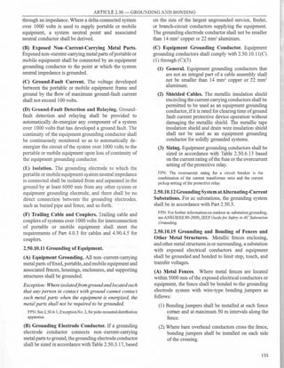

![ARTICLE 2.90 - PROTECTION AGAINST LIGHTNING
2.90.2.2 Definitions.
Air Terminal. A device capable to drawing lightning
discharge to it in preference to vulnerable parts of
the protected area. It may consist of a pointed, solid,
or tubular rod or one with special design and material
provided with a mounting base having a proper
conductor connection. [See Figure 2.90.2.2(A).J
Bonding. Connectionbetweenaconductiveorinductive
metal object and an element of a lightning protection
system to accomplish electrical continuity between the
two. [SeeFigure 2.90.2.2(B).]
Point
Base
AirTerminal
Figure 2.90.2.2(A)
Bonding
Figure 2.90.2.2(B)
Cable. A conductor formed of a number of wires
tranded together. [See Figure 2.90.2.2(C).j
Chimney. Small concrete, masonry or metal vent
protruding through the roof or attached to the side of
a building used typically in heating or venting, subject
to protection under Class I requirements. [See Figure
2.90.2.2(D).]
Class I Materials. All conductors, fittings, and fixture
necessary to protect ordinary buildings and structures
not exceeding 23 m in height. [See Figure2.90.2.2(E).J
Class II Materials. All conductors, fittings and fixture
necessary to protect ordinary buildings and structure
exceeding 23 m in height; or one which has a structural
steel frame, of any height, whose steel framing may be
substituted for lightning down conductors; or heavy
duty stacks. [See Figure 2.90.2.2(E).j
-
Chimney
Secondary Conductor
Figure 2.90.2.2(C)
Main Conductor
Heavy Duty Stack
(/:.·.�.
•;
Figure 2.90.2.2(D)
Conductors. The portion of a lightning protection
system designed to carry the lightning discharge
between air terminals and ground. (a) Main conductors
interconnect air terminals and serve as downleads
to ground. (b) Secondary conductors are used to
accomplish various bonding and other connections as
specified in this article.
137](https://image.slidesharecdn.com/pec2017part1-241003060423-f7360a96/85/Philllipine-electrical-code-2017-PART-1-pdf-160-320.jpg)
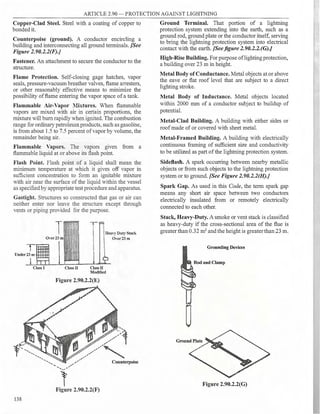
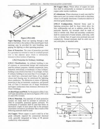
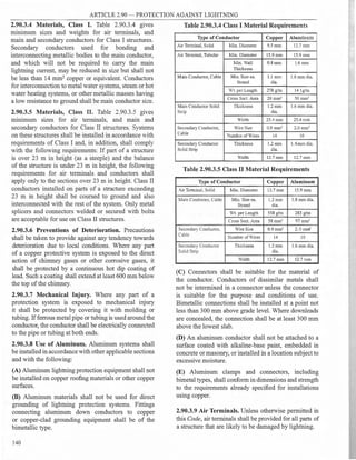
![ARTICLE 2.90 - PROTECTION AGAINST LIGHTNING
2.90.3.10 Air Terminal Design and Support.
(A) Height. The height ofairterminals shallbe such as to
bring the tip not less than 254 mm above the object to be
protected for 6000 mm maximum intervals and not less
than 600 mm above the object to be protected for 7600
mm maximum intervals. [See Figure 2.90.3.JO(A).]
(B) Supports. Air terminals shall be secured against
overturning either by attachment to the object to
be protected or by means of braces which shall be
permanently and rigidly attached to the building. Air
terminalsexceeding 600 mm inheightshallbe supported
at a point not less than one-half its height. On masonry
or brick work, holes shall be made with proper tools.
(C) Ornaments. An ornament or decoration on a free
standing, unbraced air terminal shall not present, in
any plane, a wind-resistance area in excess of 100 cm2
.
This permits the use of an ornamental ball 127 mm in
diameter. [See Figure 2.90.3.JO(C).J
2.90.3.11 Terminals on Roofs. Air terminals shall be
placed on ridges of roofs and around the perimeter
of flat or gently sloping roofs intervals not exceeding
6000 mm except that air terminals 600 mm or higher
may be placed at intervals not exceeding 7600 mm.
Air terminals shall be placed at or within 600 mm of
the ends of ridges or edges and corners of roofs. (See
Figure 2.90.3.11.)
(A) Flat or Gently Sloping Roofs. Flat or gently
sloping roofs which exceed 15 m in width or span shall
have additional air terminals at intervals not exceeding
15 m on the flat or gently sloping areas. Gently sloping
roofs are roofs having a span of 12 m or less and a pitch
of one eighth or less, or roofs having a span exceeding
12 m and a pitch of one fourth or less. [See Figures
2.90.3.ll(A)(l) and 2.90.3.ll(A)(2).]
(B) Lower Roofs. Buildings which exceed 15 m above
grade are considered to protect lower roof portions in
a one-to-one zone of protection as shown in Figure
2.90.3.l l(B)( l).Note that the distance protected on the
lower roof shall be a maximum of 15 m, regardless of
the height of the upper roof. Buildings which do not
exceed 15 m above grade are considered to protect
lower roof portions in a one-to-two zone of protection
as shown in Figure2.90.3.l l(B)(2).
(C) Dormers. Prominent dormers are those as high or
higher than the main roof and shall be protected with
air terminals, cable, down conductors and grounds as
normally specified. Dormers and projections below the
main ridge require protection on all areas extending
outside a one-to-two zone of protection as shown in
Figure 2.90.3.l l(C).
Figure 2.90.3.lO(A)
Fteerotating{ixtuxes donot
count in uea calculation
I
II
Additionalsupport required if
No additionalsupport required ornament exceeds I00 en? in
if C10S1 Jection area Jess than l00 cm2 crousection area
Figure 2.90.3.lO(C)
(D) Roofs With Intermediate Ridges. Roofs with a
series of parallel ridges shall have air terminals along
the end ridges at intervals not exceeding 7600 mm. The
141
A:
B:
C:
Ail terminals shall extend not less than 254 mm above tl!e object protected
for 6 000 mm maximum intervals and not less than 600 mm above the
object protected for 7 600 mm maximum intervals.
Air terminals over 600 mm high shall be supported.
Air terminal supports shall be at not less than one·halI the height of the air
~-·~1
,( I
I 8
l
,1
I](https://image.slidesharecdn.com/pec2017part1-241003060423-f7360a96/85/Philllipine-electrical-code-2017-PART-1-pdf-164-320.jpg)

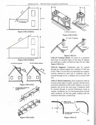
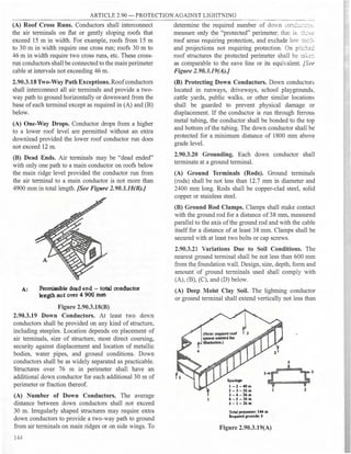


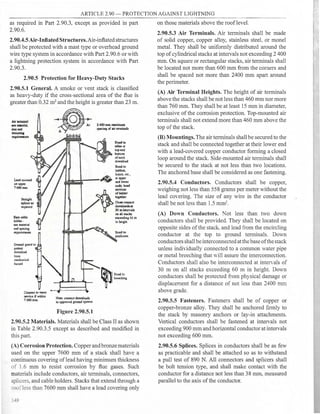

![ARTICLE 2.90 - PROTECTION AGAINST LIGHTNING
(B) Sheet Steel. Sheet steel less than 4.8 mm in
thickness may be punctured by severe strokes and shall
not be relied upon as protection from direct lightning
strokes.
(C) Rods, Masts, and Overhead Ground Wires.
(1) The zone ofprotection of an air terminal or mast
ofconducting material is conventionally taken as
the space enclosed by a cone, which has its apex
at the highest point ofthe rod or mast and a radius
at the base which bears a relation to the height.
This relation depends upon the striking distance
of the lightning stroke (the distance over which
final breakdown ofthe initial stroke to ground or
to a grounded objectoccurs) relative to the height
of the rod or mast. For a mast not exceeding
15 m in height, the zone defined by a radius of
base H equal to the height of the rod or mast has
been found to be substantially immune to direct
strokes of lightning. No part of the structure to
be protected shall extend outside of the zone of
protection. [See Figure 2.90.6.3(C)(J).}
(2) For mast heights in excess of 15 m, the zone of
protection is based on the striking distance ofthe
lightning stroke. Since the lightning stroke may
strike any grounded object within the striking
distance ofthe point from which final breakdown
to ground occurs, the zone of protection is
defined by a circular arc concave upward [See
Figure 2.90.6.3(C)(2).} The radius of the arc is
the striking distance, and the arc passes through
the tip of the mast and is tangent to the ground.
Where more than one mast is used, the arc passes
through the tips ofadjacent masts.
The striking distance is related to the peak stroke
current and thus to the severity of the liohtnino
"' "'
stroke; the greater the severity of the stroke, the
greater the striking distance. In the vast majority
of cases, the striking distance exceeds 30 m.
Accordingly, the zone bases on a strikino distance
"'
of30 m is considered to be adequately protected.
The zone of protection afforded by any
configuration of masts or other elevated
conductive grounded objects can readily b;
determined graphically. Increasing the height ofa
mast above the striking distance will not increase
zone ofprotection.
(3) Masts separate from the structure to be protected
shallbeaminimum of1800mmfromtheprotected
structure, and the clearance shall be increased by
300 mm for every 3000 mm of structure height
150
above 15 m to prevent side flashes. The masts
shall be grounded and connected at ground level
to the grounding system of the structure to be
protected. The grounding requirements of Part
2.90.3 shall apply.
(4) The zone of protection of an overhead !lround
. . . "'
wire 1s conventionally taken as a triangular prism
or wedge. For a ground wire not more than 15
m above ground, one-half the base of the wedge
(H) equal to the height of the lowest point of the
overhead ground wire is considered to provide
protection. [See Figure 2.90.6.3(C)(I).] For
a ground wire more than 15 m above ground,
the zone of protection is based on a striking
distance of 30 m. [See Figure 2.90.6.3(C)(2).}
The supporting masts shall have a clearance
from the protected structure as under Section
2.90.6.3(C)(3). The ground wire material shall
be noncorrosive for the conditions existing at the
side and shall not be smaller in cross-sectional
area than 14 mm2
•
(5) The minimum clearance between the overhead
ground wires and the highest projection on the
protected structure shall be 1800 mm. For each
3000 mm of lead between a point on the ground
wire midway between the supporting masts and
ground in excess of 18 m, the clearance shall be
increased by 300 mm. The ground wire(s) shall be
grounded and interconnected with the !lroundino
"' "'
system ofthe structure to be protected.
(6) Masts of wood used either separately or with
ground wires, shall haYe an air terminal securely
mounted to the top of the pole [See Figure
2.90.6.3(C){6)] and connected to the grounding
system. As an alternative. an o·erhead ground
wire or a down conductor, extending above or
across the top ofthe pole, maybeused as a suitable
air terminal. In case of an overhead ground-wire
system, the pole guy wire may be used as the
down conductor [See Figure 2.90.6.3(C)(6)].
For metallic masts, the air terminal and the down
conductor shall not be required.
2.90.6.4 Protection ofAboveground Tank Containing
Flammable Liquids at Atmosphere Pressure.
(A) The contents of metallic tanks with steel roofs of
riveted, bolted, or welded construction, with or without
supporting members, used for the storage offlammable
liquids at atmospheric pressure are considered to be
protected against lightning (inherently self-protecting)
ifthe following requirements are met:](https://image.slidesharecdn.com/pec2017part1-241003060423-f7360a96/85/Philllipine-electrical-code-2017-PART-1-pdf-173-320.jpg)


![ARTICLE 3.0- GENERAL REQUIREMENTS FOR WIRING METHODS AND MATERIALS
Exception No. 2: A listed and marked steel plate
less than 1.6 mm thick that provides equal or better
protection against nail or screw penetration shall be
permitted.
(B) Nonmetallic-Sheathed Cables and Electrical
Nonmetallic Tubing Through Metal Framing
Members.
(1) Nonmetallic-Sheathed Cable. In both exposed
and concealed locations where nonmetallic-
sheathed cables pass through either factory- or
field-punched, cut, or drilled slots or holes in
metal members, the cable shall be protected by
listed bushings or listed grommets covering all
metal edges that are securely fastened in the
opening prior to installation of the cable.
(2) Nonmetallic-Sheathed Cable and Electrical
Nonmetallic Tubing. Where nails or screws are
likely to penetrate nonmetallic-sheathed cable
or electrical nonmetallic tubing, a steel sleeve,
steel plate. or steel clip not less than 1.6 mm in
thickness shall be used to protect the cable or
tubing.
Exception: A listed and marked steel plate less than
1.6 mm thick that provides equal or better protection
against nail or screw penetration shall be permitted.
(C) Cables Through Spaces Behind Panels Designed
to Allow Access. Cables or raceway-type wiring
methods, installed behind panels designed to allow
access, shall be supported according to their applicable
articles.
(D) Cables and Raceways Parallel to Framing
Members and Furring Strips. In both exposed and
concealed locations, where a cable- or raceway-type
wiring method is installed parallel to framing members,
such as joists, rafters, or studs, or is installed parallel
to furring strips, the cable or raceway shall be installed
and supported so that the nearest outside surface of
the cable or raceway is not less than 32 mm from the
nearest edge of the framing member or furring strips
where nails or screws are likely to penetrate. Where this
distance cannot be maintained, the cable or raceway
shall be protected from penetration by nails or screws
by a steel plate, sleeve, or equivalent at least 1.6 mm
thick.
Exception No. ]: Steel plates, sleeves, or the equivalent
shall not be required to protect rigid metal conduit,
intermediate metal conduit, rigid nonmetallic conduit,
or electrical metallic tubing.
Exception No. 2: For concealed work in finished
buildings, orfinishedpanelsfor prefabricatedbuildings
where such supporting is impracticable, it shall be
permissible to fish the cables between access points.
Exception No. 3: A listed and marked steel plate
less than 1.6 mm thick that provides equal or better
protection against nail or screw penetration shall be
permitted.
(E) Cables, Raceways, or Boxes Installed in or Under
Roof Decking. A cable, raceway, or box, installed in
exposed or concealed locations under metal-corrugated
sheet roof decking, shall be installed and supported so
there is not less than 38 mm measured from the lowest
surface of the roof decking to the top of the cable,
raceway, or box. A cable, raceway, or box shall not be
installed in concealed locations in metal-corrugated,
sheet decking-type roof.
FPi: Roof decking material is often repaired or replaced after
the initial raceway or cabling and roofing installation and may be
penerrated by the screws or other mechanical devices designed
to pro,·ide "hold down" strength of the waterproof membrane or
roof insulating material.
Exception: Rigid metal conduit and intermediate metal
conduit shall not be required to comply ·with 3.0.1.4(E).
(F) Cables and Raceways Installed in Shallow
Grooves. Cable- or raceway-type wiring methods
installed in a groove, to be covered by wallboard, siding,
paneling, carpeting, or similar finish, shall be protected
by 1.6 mm thick steel plate, sleeve, or equivalent or by
not less than 32-mm free space for the full length ofthe
groove in which the cable or raceway is installed.
Exception No. 1: Steel plates, sleeves, or the equivalent
shall not be required to protect rigid metal conduit,
intermediate metal conduit, rigid nonmetallic conduit,
or electrical metallic tubing.
Exception No. 2: A listed and marked steel plate
less than I. 6 mm thick that provides equal or better
protection against nail or screw penetration shall be
permitted.
(G) Insulated Fittings. Where raceways contain
22 mm2 or larger insulated circuit conductors, and
these conductors enter a cabinet, a box, an enclosure,
or a raceway, the conductors shall be protected by
an identified fitting providing a smoothly rounded
insulating surface, unless the conductors are separated
from the fitting or raceway by identified insulating
material that is securely fastened in place.
Exception: Where threaded hubs or bosses that are
an integral part of a cabinet, box, enclosure, or
raceway provide a smooth(v rounded or.flared entry.for
conductors.
155](https://image.slidesharecdn.com/pec2017part1-241003060423-f7360a96/85/Philllipine-electrical-code-2017-PART-1-pdf-178-320.jpg)

![ARTICLE 3.0 - GENERAL REQUIREMENTS FOR WIRING METHODS AND MATERIALS
Tab]e 3.0.1.5 Minimum Cover Requirements, 0 to 1000 Volts, Nomina], Burial in Millimeters
Type ofWiring Method or Circuit
Column3
Nonmetallic
Column4
Column 5
Raceways
Residential Branch
Circuits for Control
Listed for
Circuits Rated 230
of Irrigation and
Direct Burial
Volts or Less with
Landscape Lighting
Column 2 Without
GFCI Protection and
Limited to Not More
Column 1 Rigid Metal Concrete
Maximum Overcurrent
Than 30 Volts and
Direct Burial Conduit or Encasement
Protection of 20 Amperes
Installed with Type UF
Cables or Intermediate or Other or in Other Identified
Conductors Metal Conduit Approved
(mm)
('able or Raceway
Location ofWiring Method or Circuit (mm) (mm) Raceways (mm) (mm)
All locations not specified below 600 150 450 300 150"·b
In trench below 50 mm thick concrete or 450 150 300 150 150
equivalent
Under a building 0 (in raceway 0 0 0 (in raceway or Type MC 0 (in raceway or Type
or Type ~1( or or Type MI cable identi- MC or Type MI cable
Type MI cable fled for d.irect burial) identified for direct
identified for burial)
direct burialJ
Under minimum of 100 mm thick concrete --l-50 100 100 150 (direet burial} 150 (direct burial)
exterior slab with no ,-ehicular traffic and the
100 (in raceway) l00 (in raceway)
slab extending not less than 150 = beyond
the underground installa1ion
Cnder ,rree1s. highways, roads. alleys_ dri,-e- 600 600 600 600 600
wa~;- and park-ng !ms
One- and two-family dwellrng drieways 450 -l5U 450 300 450
and omdoor parking areas, and used only for
d"-elling-related purposes
In or under airport runways, including 450 450 450 450 450
adjacent areas where trespassing prohibited
'A lesser cte th shall be errmttect where s ec1llec rn the mstallat1on mstructJoris ot a 1stect L
ow-voltaoe 110:htrn s stern.
p p p "'"' gy
hA depth of 150 mm shall be permitted for pool, spa, and fountain lighting, installed in a nonmetallic raceway, limited to not more than
30 volts where part ofa listed low-voltage lighting system.
Notes:
I. Cover is defined as the shortest distance in millimeters measured between a point on the top surface ofany direct-buried conductor, cable, conduit, or other
raceway and the top surface offinished grade, concrete, or similar cover.
2. Raceways approved for burial only where concrete encased shall require concrete envelope not less than 50 mm thick.
3_Lesser depths shall be permitted where cables and conductors rise for terminations or splices or where access is otherwise required.
4. Where one ofthe wiring method types listed in Columns 1- 3 is used for one ofthe circuit types in Columns 4 and 5, the shallowest depth oflmrial shall be
permitted.
5. Where solid rock prevents compliance with the cover depths specified in this table, the wiring shall be installed in metal or nonmetallic raceway permitted for
direct buriaL The raceways shall be covered by a minimum of50 mm ofconcrete extending down to rock.
raceway or multiconductor cable shall contain all or cables shall be arranged so as to prevent damage to
conductors of the same circuit, including equipment the enclosed conductors or to equipment connected to
grounding conductors. Each direct-buried single the raceways.
conductor cahle shall be located in close proximity in
the trench to the other single conductor cables in the
same parallel set ofconductors in the circuit, including
equipment grounding conductors.
Exception No. 2: Isolated phase, polarity, grounded
conductor, and equipment grounding and bonding
conductor installationsshallbepermittedin nonmetallic
raceways or cables with a nonmetallic covering
or nonmagnetic sheath in close proximity where
conductors are paralleled as p ermitted in 3.10.2.1(H),
and where the conditions of3.0.l.20(B) are met.
(J) Earth Movement. Where direct-buried conductors,
raceways, or cables are subject to movement by
settlement or frost, direct-buried conductors, raceways,
FPN: This section recognizes "S" loops in underground direct
burial cables and conductors to raceway transitions, expansion
fittings in raceway risers to fixed equipment, and, generally,
the provision of flexible connections to equipment subject to
settlement or frost heaves.
(K) Directional Boring. Cables or raceways installed
using directional boring equipment shall be approved
for the purpose.
3.0.1.6 Protection Against Corrosion and
Deterioration. Raceways, cable trays, cablebus,
auxiliary gutters, cable armor, boxes, cable sheathing,
cabinets, elbows, couplings, fittings, supports, and
support hardware shall be of materials suitable for the
environment in which they are to be installed.
157](https://image.slidesharecdn.com/pec2017part1-241003060423-f7360a96/85/Philllipine-electrical-code-2017-PART-1-pdf-180-320.jpg)


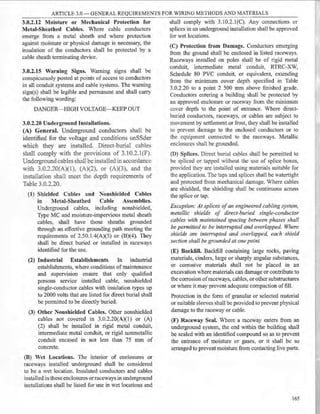
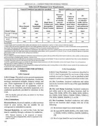
![ARTICLE 3.10 ~ CONDUCTORS FOR GENERAL WIRING
relays, solenoids, and similar control devices, or for
frequencies of 360 Hz and higher, provided all of the
following apply:
(a) They are contained within the same raceway or
cable.
(b) The ampacity of each individual conductor is
sufficient to carry the entire load current shared
by the parallel conductors.
(c) The overcurrent protection is such that the
ampacity ofeach individual conductor will not be
exceededifone or more oftheparallel conductors
become inadvertently disconnected.
Exception No. 2: Under engineering supervision, 30
mm2 and 38 mm2 grounded neutral conductors shall
be permitted to be installed in parallel for existing
installations.
FPN to Exception No. 2: Exception No. 2 can be used to alleviate
overheating of neutral conductors in existing installations due to
high content oftriplen harmonic currents.
(2) Conductor and Installation Characteristics.
The paralleled conductors in each phase, polarity,
neutral, grounded circuit conductor, equipment
grounding conductor, or equipment bonding
jumper shall comply with all ofthe following:
(1) Be the same length.
(2) Consist of the same conductor material.
(3) Be the same size in square millimeter area.
(4) Have the same insulation type.
(5) Be terminated in the same manner.
(3) Separate Cables or Raceways. Where run
in separate cables or raceways, the cables
or raceways with conductors shall have the
same number of conductors and shall have the
same electrical characteristics. Conductors of
one phase, polarity, neutral, grounded circuit
conductor, or equipment grounding conductor
shall not be required to have the same physical
characteristics as those ofanother phase, polarity,
neutral, grounded circuit conductor, or equipment
grounding conductor.
(4) Ampacity Adjustment. Conductors installed
in parallel shall comply with the provisions of
3.10.2.6(B)(3)(a).
(5) Equipment Grounding Conductors. Where
parallel equipment grounding conductors are
used, they shall be sized in accordance with
2.50.6.13. Sectioned equipment grounding
168
conductors smallerthan 50 mm2 shall be permitted
in multiconductor cables, ifthe combined square
millimeter area of the sectioned equipmem
bonding conductors in each cable complies with
2.50.6.13.
(6) Bonding Jumpers. Where parallel equipmen,
bondingjumpers or supply-side bonding jumpers
are installed in raceways, they shall be sized and
installed in accordance with 2.50.5.13.
3.10.2.6 Ampacities for Conductors Rated O- 2000
Volts.
(A) General.
(1) Tables or Engineering Supervision. Ampacitics
for conductors shall be permitted to be
determined by tables as provided in 3.10.2.6(B)
or under engineering supervision, as provided in
3. I0.2.6(C).
FPN No. 1: Ampacities provided by this section do not take
voltage drop into consideration. See 2.10.2.2(A), FPN No. 4, for
branch circuits and 2. l5.l.2(A), FPN No. 2, for feeders.
FP ' No. 2: For the allowable ampacities ofType MTW wire, see
Table 13.5.1 in NFPA 79-2012, Electrical Standardfor Industrial
lv[achinery.
(2) Selection of Ampacity. Where more than one
ampacity applies for a given circuit length, the
lowest value shall be used.
Exception: Where different ampacities app(v to portions
ofa circuit, the higher ampacity shall be permitted to be
used ifthe total portion(s) ofthe circuit with the lower
ampacity does not exceed the lesser of3 000 mm or 10
percent ofthe total circuit.
FPN: See 1.10.I .14(C) for conductor temperature limitations due
to termination provisions.
(3) Temperature Limitation of Conductors. No
conductor shall be used in such a manner that its
operating temperature exceeds that designated for the
type of insulated conductor involved. In no case shall
conductors be associated together in such a way, with
respect to type ofcircuit, the wiring method employed,
or the number of conductors, that the limiting
temperature of any conductor is exceeded.
FPN No. 1: The temperature rating of a conductor [see Table
3.10.3.l(A) and Table 3.10.3.l(C)] is the maximum temperature,
at any location along its length, that the conductor can withstand
over a prolonged time period without serious degradation. The
allowable ampacity tables, the ampacity tables of Article 3.10
and the ampacity tables ofAppendix B, the ambient temperature
correction factors in 3.10.2.6(8)(2), and the notes to the tables
provide guidance for coordinating conductor si:zes, types.
allowable ampacities, ampacities, ambient temperatures, and
number of associated conductors. The principal determinants of
operating temperature are as follows:](https://image.slidesharecdn.com/pec2017part1-241003060423-f7360a96/85/Philllipine-electrical-code-2017-PART-1-pdf-191-320.jpg)


![ARTICLE 3.10 - CONDUCTORS FOR GENERAL WIRING
(3) The manufacturer's name, trademark, or other
distinctive marking by which the organization
responsible for the product can be readily
identified.
(4) The square millimeter size or area.
FPN: See Conductor Properties, Table 10.1.l.8, for conductor
area expressed in SI units for conductor sizes specified in square
millimeter size or area.
(5) Cable assemblies where the neutral conductor is
smaller than the ungrounded conductors shall be
so marked.
(B) Method of Marking.
(1) Surface Marking. The following conductors
and cables shall be durably marked on the
surface. The square millimeter size or area shall
be repeated at intervals not exceeding 600 mm.
All other markings shall be repeated at intervals
not exceeding 1000 mm.
(1) Single-conductor and multiconductor rubber-
and thermoplastic-insulated wire and cable
(2) Nonmetallic-sheathed cable
Table 3.10.2.6(B)(16) Allowable Ampacities oflnsulated Conductors Rated Up to and Including 2000 Volts,
60°C Through 90°C, Not More Than Three Current-Carrying Conductors in Raceway, Cable, or Earth
(Directly Buried), Based on Ambient Temperature of 30°C*
Temperature Rating of Conductor [See Table 3.10.3.l(A)]
60°C 1s0 c 90°c 60°C 15°c 90°c
Types Types
RHW, Types TBS, SA, SIS, RHW,
THHW, FEP, FEPB, Ml, RHH, THHW, Types TBS, SA, SIS, RHH,
THW, RH'W-2, THHN, THHW, THW. RHW-2, THHN, THHW,
THWN, THW-2, THWN-2, TH~, THV-2, THWN-2, USE-2,
Types XHHW, USE-2, XHH, XHHW, Types X.HHW, XHH, XHHW, XHHW-2,
Conductor TW,UF USE, ZW XHHW-2, ZW-2 TW,L'F rsE ZW-2
Size mmi COPPER ALCII:T>I OR COPPER-CLAD ALUUNUM
2.0(1.6)* 15 20 ..., -
_:, - - -
3.5(2.0)* 20 ') -
_:, 30 ''- ~o 25
5.5(2.6)* 30 35 40 "" ~o 35
--
8.0(3.2) 40 50 55 30 40 45
14 55 65 75 40 50 65
22 70 85 95 55 65 80
30 85 100 115 65 80 90
38 100 115 130 75 90 105
50 115 140 150 90 110 125
60 130 155 170 100 120 135
80 155 190 205 120 145 165
100 185 220 240 140 170 190
125 210 255 285 165 200 225
150 240 285 320 190 230 255
175 260 305 345 205 245 275
200 275 325 360 220 265 300
250 315 375 425 255 305 345
325 370 435 490 300 355 405
375 395 470 530 315 380 430
400 400 480 535 320 385 440
500 445 530 595 365 435 485
*Refer to 3.10.2.6(B)(2)(a) for the ampacity correction factors where the ambient temperature is other than 30°C. Refer to 3.10.2.6(B)(3)(a) for
more than three current-carrying conductors.
**Refer to 2.40.l .4(D) for conductor overcurrent protection limitations.
174
' t](https://image.slidesharecdn.com/pec2017part1-241003060423-f7360a96/85/Philllipine-electrical-code-2017-PART-1-pdf-197-320.jpg)
![ARTICLE 3.10 - CONDUCTORS FOR GENERAL WIRING
(3) Service-entrance cable
(4) Underground feeder and branch-circuit cable
(5) Tray cable
(6) Irrigation cable
(7) Power-limited tray cable
(8) Instrumentation tray cable
(2) Marker Tape. Metal-covered multiconductor
cables shall employ a marker tape located within
the cable and running for its complete length.
Exception No. 1: Type Ml cable.
Exception No. 2: Type AC cable.
Exception No. 3: The information required in
3.10.3.17(A) shall be permitted to be durably marked
on the outer nonmetallic covering of Type MC, Type
ITC, or Type PLTC cables at inten,als not exceeding
1000mm.
Exception No. 4: The information required in
3.10.3.l 7(A) shall bepermitted to be durably markedon
a nonmetallic covering under the metallic sheath ofType ITC
or Type PLTC cable at intervals not exceeding 1000 mm.
Table 3.10.2.6(B)(l7) Allowable Ampacities of Single-Insulated Conductors Rated Up to and Including
2000 Volts in Free Air, Based on Ambient Temperature of 30°C*
Temperature Rating of Conductor [See Table 3.10.3.l(A)]
60°C 1s0 c 90°c 60°C 1s0 c 90°c
Types
RHV,
THHW, Types TBS, SA, SIS,
TH,", FEP, FEPB, :'11, RHH, Types RHW, Types TBS, SA, SIS, RHH,
TRW;', RHW-2, THHN, THHW, THHW, RHW-2, THHN, THHW,
>...'HH"~ THW-2, THW~-2 l"SE- THW, THW-2, THWN-2, USE-2,
Types LSE. 2, XHH, XHHW, XHHW- Types THW;li, XHH, XHHW, XHHW-2,
Conductor
T.-. l -F zw 2, ZW-2 TW,l"F XHHY, LSE ZW-2
Size mm? COPPER ALCIL"C1 OR COPPER-CLAD ALUMINUM
2.0(1.6)* ..,.::
30 35 - - -
--
3.5(2.0)* 30 35 ~o 25 30 35
5.5(2.6t* ~ 5:1 :;;.;;; 3~ 40 40
- -
.OC-- ) ...... 65 -.;; ;5 50 55
- -
1~ 80 100 110 65 80 85
T"l
105 130 ... -:--~ 85 105 115
--
30 1-5 150 65 95 115 130
38 I45 175 195 115 135 155
50 180 210 235 135 165 185
60 200 235 265 155 185 210
80 245 290 325 185 225 255
100 285 340 380 220 265 295
125 335 400 445 260 310 350
150 375 445 505 295 355 400
175 410 495 560 325 390 440
200 440 530 590 345 410 465
250 510 620 685 405 485 545
325 600 720 800 475 560 640
375 645 775 875 510 615 690
400 660 795 890 520 630 705
500 755 905 1020 605 730 820
*Refer to 3.10-2.6(B)(2)(a) for the ampacity correction factors where the ambient temperature is other than 30°C.
**Refer to 2.40.l.4(D) for conductor overcurrent protection limitations_
175](https://image.slidesharecdn.com/pec2017part1-241003060423-f7360a96/85/Philllipine-electrical-code-2017-PART-1-pdf-198-320.jpg)
![ARTICLE 3.10 - CONDUCTORS FOR GENERAL WIRING
Table 3.10.2.6(B)(18) Allowable Ampacities of Insulated Conductors Rated Up to and Including 2000 Volts,
150°C Through 250°C. Not More Than Three Current-Carrying Conductors in Raceway or Cable, Based on
Ambient Air Temperature of 40°C'~
Temperature Rating of Conductor [See Tab)e 3.10.3.l(A)J
150°C 200 °C 250°C 1so0 c
Types
FEP, Types TBS, SA, SIS, RHH, RHW-2. THH;'..
FEPB, THHW, THW-2. THW:"-2. rsE-2. XHH.
Types Z PFA, SA Types PFAH, TFE XHITTY. XHHW-2. ZY-2
Conductor
COPPER
NICKEL OR NICKEL-COATED ALU'.11":T,1 OR COPPER-CLAD
Size mm2 COPPER ALCI[T,1
2.0() .6)* 32 34 37 -
3.5(2.0)* 45 47 57 31
5.5(2.6)* 57 62 76 ~5
8.0(3.2) 71 78 88 ::'." ...'
14 101 116 123 ;~
22 124 129 153 g-
- J
30 138 147 165 107
38 162 172 188 127
50 194 206 220 152
60 222 230 241 175
80 267 275 286 210
100 312 325 339 244
*Refer to 3. l0.2.6(B)(2)(b) for the ampacity correction facto ·he the aa:biem temperarure is other than 40°C. Refer to 3.10.2.6(B)(3)(a) for
more than three current-carrying conductors.
Table 3.10.2.6(B)(l9) Allowable Ampacities of Single-Insulated Conductors, Rated Up to and Including 2000
Volts, 150°C Through 250°C. in Free Air. Based on Ambient Air Temperature of 40°C*
Temperature Rating of Conductor [See Table 3.10.3.l(A)]
150°C 200 °C 2so0 c 150°C
Types
FEP Types TBS, SA, SIS, RHH, RHW-2, THHN,
FEPB, THHW, THW-2, THWN-2, USE-2, XHH,
Types Z PFA, SA Types PFAH, TFE XHHW, XHHW-2, ZW-2
Conductor :"ICKEL OR NICKEL-COATED ALUMINUM OR COPPER-CLAD
Size mm2 COPPER COPPER ALUMINUM
2.0(1.6)* 43 51 56 -
3.5(2.0)* 63 72 82 49
5.5(2.6)* 83 94 111 65
8.0(3.2) 100 117 134 78
14 164 174 217 118
22 197 228 289 153
30 220 253 329 171
38 256 301 385 199
50 306 360 480 237
60 345 413 523 270
80 418 507 657 325
100 497 592 781 386
*Refer to 3.10.2.6(B)(2)(b) for the ampacity conection factors where the ambient temperature is other than 40°C.
176](https://image.slidesharecdn.com/pec2017part1-241003060423-f7360a96/85/Philllipine-electrical-code-2017-PART-1-pdf-199-320.jpg)
![ARTICLE 3.10--CONDUCTORS FOR GENERAL WIRING
FPN: Included in the group of metal-covered cables are Type ( 1) Type MC cable
AC cable (Article 3.20), Type MC cable (Article 3.30), and lead-
sheathed cable. (2) Tray cable
(3) Tag Marking. The following conductors and
cables shall be marked by means of a printed tag
attached to the coil, reel, or carton:
(1) Type MI cable
(2) Switchboard wires
(3) Metal-covered, single-conductor cables
(4) Type AC cable
(4) Optional Marking of Wire Size. The
infom1ation required in 3.10.3.l7(A)(4) shall
be permitted to be marked on the surface of the
individual insulated conductors for the following
multiconductor cables:
(3) Irrigation cable
(4) Power-limited tray cable
(5) Power-limited fire alarm cable
(6) Instrumentation tray cable
(C) Suffixes to Designate Number of Conductors.
A type letter or letters used alone shall indicate a
single insulated conductor. The letter suffixes shall be
indicated as follows:
(I) D - For two insulated conductors laid parallel
within an outer nonmetallic covering
(2) M -- For an assembly of two or more insulated
conductors twisted spirally within an outer
nonmetallic covering
Table 3.10.2.6(B)(20) Ampacities of Not More Than Three Single Insulated Conductors, Rated Up to and
Including 2000 Volts, Supported on a Messenger, Based on Ambient Air Temperature of40°C*
Temperature Rating of Conductor [See Table 3.10.3.l(A)]
1s0 c 90 °C 75°c 90 °C
Types
Types RH, RHV,
Type THHN, THHW, THY-2, THHW, Type
RH, RHW, THHW, THWN-2, RHH, RWH- THW, THHN, THHW, RHH, XHHW, RHW-
THW,THWN, 2, USE-2, XHHY-2, THWN, 2, XHHW-2, THW-2, THWN-2, USE-
Conductor XHH,ZW ZW-2 ZHHW 2,ZW-2
Size mm2 COPPER ALUMINUM OR COPPER-CLAD ALUMINUM
8.0(3.2) 53 62 41 48
14 I 80 9-1- 62 73
'1'1
105 121 81 94
--
30 116 136 91 106
38 138 162 107 126
50 165 193 129 150
60 187 218 146 170
80 227 266 178 208
100 270 315 210 246
I"' -
_:) 316 369 248 288
150 363 423 285 331
175 390 460 310 360
200 416 486 327 382
250 496 581 392 458
325 576 674 458 535
375 630 740 505 590
400 659 771 529 617
500 741 870 606 709
*Refer to 3.10.2.6(B)(2)(b) for the ampacity correction factors where the ambient temperature is other than 40°C. Refer to 3.10.2.6(B)(3)(a) for
more than three current-carrying conduetors.
177](https://image.slidesharecdn.com/pec2017part1-241003060423-f7360a96/85/Philllipine-electrical-code-2017-PART-1-pdf-200-320.jpg)
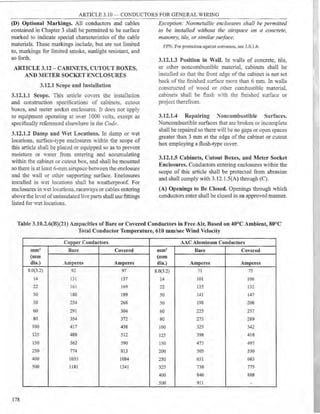
![Ootalll
ARTICLE 3.10 - CONDUCTORS FOR GENERAL TIRING
Table 3.10.2.51(C)(4) Ambient Temperature
Correction Factors
For ambient temperatures other than 40°C. multiply the
290 mrn >: 290 mm
Electrical duct bank
O!"!e e:octrical duct
190mm
Oetail2
475 mm x 475 mm
Electrical duct bank
To,ee ele:etrical due.ti.
allowable ampacities specified in the ampacity tables by the
•
or
!·.~~~.~~<.;)~ I
~
190mm 190mm
675 mm '< 290 mm
Electncai duct bank:
Three elec!JicaJ dt.icts
1•
Oe!a,16
&.'rie<!3
CO!"IO'.JC:Cf'
ca::les
DetaJIT
Suried triplexetl
cabJ9r; (1 circuit)
,somm
Oetoll3
47S mm x675 mm
Electocal duct bank
Six etec!r1cal ducts
or
190mm 190mm
675mmx475mm
Electrical duct bank
Six electrical ducts
~--~~..--:
... A
Detail&
Bvriorj h1plexed
cables (2 clrGuits)
1S0rrm 1!iCr!'.N1
~~
190nn 190mm 500mn, 190nm 190 mm
. =
1 ~1=·.,..___
1 ------=-' -- ·r--11
Detaj!10
• • •
Debril 9
&......:!~or
~(10,--,i:J
Buried sir.~Je-conduclor
~bies (2 circuits)
Nc:a. M:n:mt.im buraJ oeptrts to lop electricaJ ducts or eabtes. shall be
tl'i 3cCC.-dance ¥oith Seajen 3.0.2.20.Maximum depu, 10 th81op
cf e!edl".eal d'<Jei banks sha.!I be 7.50 mm and maximum depth to
the tcp of direci buried cables shall be 900 mm.
Legend
~ Backfiif (eartn or concrtit&)
Q Electrical duct
• Cable or cables.
Figure 3.10.2.51(C)(3) Cable Installation
Dimensions for Use with Table 3.10.2.51(C)(77)
Through Table 3.10.2.51(C)(86).
appropriate correction factor shown below.
Temperature Rating of
Conductor
Ambient Temperature (0 C) 90°C I05°C
10 or less 1.26 1.21
11 - 15 1 ..,..,
1.18
J.---
16 - 20 l.l S 1.1-l
21 - 25 '
.. 1.11
.:. .1 ~
26 - 30 ;.1 1.07
31 - 35 1.0~ 1.04
36 -40 1 1
41 - 45 0.'15 0.96
46- 50 O.S9 0.92
51 - 5:5 0.~4 0.88
56- 60 o::·- 0.83
61 - 65 o.-: 0.78
66 - 70 0.63 0.73
71 - 75 U.::'~ 0.68
76 - 80 o..;~ 0.62
81 - 85 o.:.::::: 0.55
86 - 90 - 0.48
91 - 95 - 0.39
96 - 100 - 0.28
Table 3.10.2.51(C)(67) Ampacities of Insulated Single Copper Conductor Cables Triplexed in Air Based on
Conductor Temperatures of 90°C and 105°C and Ambient Air Temperature of 40°C
Temperature Rating of Conductor [See Table 3.10.3.l(C).]
2001 - 5000 Volts 5001 - 35000 Volts 2001 - 5000 "olts 5001 - 35000 Volts
Ampacity Ampacity Ampacity Ampacity
Conductor 90°c 1os0 c 90°c 105°C Conductor 90°c 10s0 c 90°C 105°C
Size [mm2 Type TypeMV- Type Type Size [mm2 Type Type Type Type
(mm dia.)] MV-90 105 MV-90 MV-105 (mm dia.)] MV-90 :IY-105 .<IV-90 MV-105
8.0(3.2) 65 74 - - 80 290 320 300 340
14 90 99 100 110 100 335 375 345 390
22 120 130 130 140 125 375 415 380 430
30 160 175 170 195 175 465 515 470 525
38 185 205 195 225 250 580 645 580 650
50 215 240 225 255 375 750 835 730 820
60 250 275 260 295 500 880 980 850 950
*Refer to 3.10.2.51 (C)(4) for the ampacity correction factors where the ambient air temperature is other than 40°C.
179](https://image.slidesharecdn.com/pec2017part1-241003060423-f7360a96/85/Philllipine-electrical-code-2017-PART-1-pdf-202-320.jpg)
![ARTICLE 3.10 - CONDUCTORS FOR GENERAL WIRING
Table 3.10.2.51(C)(68) Ampacities of Insulated Single Aluminum Conductor Cables Triplexed in Air Based on
Conductor Temperatures of 90°C and 105°C and Ambient Air Temperature of 40°C'''
Temperature Rating of Conductor (See Table 3.10.3.l(C).J
2001 - 5000 Volts 5001 - 35000 Volts 2001 - 5000 Volts 5001 - 35000 Volts
Ampacity Ampacity Ampacity Ampacity
Conductor 90°C 105°C 90°C 105°C Conductor 90°C 105°C 90°C 105°C
Size [mm2 Type TypeMV- Type Type Size [mm2 Type Type Type Type
(mm dia.)] MV-90 105 MY-90 MV-105 (mm dia.)) :MV-90 MV-105 MV-90 MV-105
8.0(3.2) 50 57 - - 80 225 250 230 265
14 70 77 75 84 100 265 290 270 305
22 90 100 100 110 125 295 325 300 335
30 125 135 130 150 175 365 405 370 415
38 145 160 150 175 250 460 510 460 515
50 170 185 175 200 375 600 665 590 660
60 195 215 200 230 500 715 800 700 780
*Refer to 3.10.2.51(C)(4) for the ampacity correction factors where the ambient air temperature is other than 40°C.
Table 3.10.2.51(C)(69) Ampacities of Insulated
Single Copper Conductor Isolated In Air Based On
Conductor Temperatures of 90°C and 105°C and
Ambient Air Temperature of 40°C
Temperature Rating of Conductor [See Table 3.10.3.l(C).)
2001 - 5000 Volts 5001 - 15000 15001 - 35000
Ampacity Volts Ampacity YoltsAmpacity
90°c 105°C 90°c 105°C 90°c 105°C
Conductor Type Type Type Type Type Type
Size (mm' MV- MV- lIV- I- :IY- '.IY-
(mm dia.)] 90 105 90 105 90 105
8.0(3.2) 83 93 - - - -
14 !JO 120 110 125 - -
22 145 160 ISO 165 - -
30 190 215 195 215 - -
38 225 250 225 250 225 250
50 260 290 260 290 260 290
60 300 330 300 335 300 330
80 345 385 345 385 345 380
100 400 445 400 445 395 -l-+5
125 445 495 445 495 440 490
175 550 615 550 610 545 605
250 695 775 685 765 680 755
375 900 1000 885 990 870 970
500 1075 1200 1060 1185 1040 1160
*Refer to 3.10.2.5l (C)(4) for the ampac1ty correct10n factors where
the ambient air temperature is other than 40°C.
180
Table 3.10.2.51(C)(70) Ampacities of Insulated
Single Aluminum Conductor Isolated in Air Based
on Conductor Temperatures of 90°C and 105°C
and Ambient Air Temperature of 40°C*
Temperature Rating of Conductor [See Table 3.10.3.l(C).J
2001 - 5000 Yolts 5001 - 15000 15001 - 35000
..mpacity Yolts Ampacity VoltsAmpacity
90cc 105°c 90°c 105°C 90°c 105°C
Conductor Type T:·pe T:ype Type Type Type
Size [mm' .IY- .I-- ~I'- MV- MV- M:V-
(mm clia.)J 90 105 90 105 90 105
8.0(3.2) 64 7! - - - -
14 85 95 87 97 - -
22 ]15 125 115 130 - -
30 150 165 150 170 - -
38 175 195 175 195 175 195
50 200 225 200 225 200 225
60 230 260 235 260 230 260
80 270 300 270 300 270 300
100 310 350 310 350 310 345
125 345 385 345 385 345 380
175 430 480 430 480 430 475
250 545 605 535 600 530 590
375 710 790 700 780 685 765
500 855 950 840 940 825 920
*Refer to 3.10.25l(C)(4) for the ampacity correction factors where
the ambient air temperature is other than 40°C.](https://image.slidesharecdn.com/pec2017part1-241003060423-f7360a96/85/Philllipine-electrical-code-2017-PART-1-pdf-203-320.jpg)
![ARTICLE 3.10 - CONDUCTORS FOR GENERAL WIRING
Table 3.10.2.51(C)(71) Ampacities of an Insulated
Three-Conductor Copper Cable Isolated in Air Based
on Conductor Temperatures of 90°C and 105°C and
Ambient Air Temperature of 40°C1'
Temperature Rating of Conductor [See Table 3.10.3.l(C).J
2001 - 5000 Volts 5001 - 35000 Volts
Ampacity Ampacity
Conductor 90°c 90°c
Size [mm' TypeMV- 105°CType Type lfV- 105°C Type
(mm dia.)) 90 MV-105 90 MV-105
8.0(3.2) 59 66 - -
14 79 88 93 105
22 105 115 120 135
30 140 154 165 IS5
38 160 180 185 210
50 185 205 215 240
60 215 240 2-1-5 ~':"5
80 250 280 285 315
100 285 320 325 360
125 320 355 360 400
175 395 4-H) ~35 ..;.90
250 485 ~~- 535 600
:) 5 615 6S5 6-o -.:;;;:-
500 705 :-90 :-:-o S60
"'Reterto .). l J.~.- l(L l{4l or tlle a..upa.:iry co!T".....:;til)n tacrors ·here
the ambient air remperarure is orber than ..J.() •C.
Table 3.I0.2.51(C)(73) Ampacities of an Insulated
Triplexed or Three Single-Conductor Copper Cables
in Isolated Conduit in Air Based on Conductor
Temperatures of 90°C and 105~C and Ambient Air
Temperature of40~c
Temperature Rating of Conductor (See Table 3.10.3.l(C).J
2001 - 5000 Volts 5001 - 35000 Yolts
Ampacity Ampacity
Conductor 90°c 90°C
Size [mm2 TypeMV- I05°C Type T~pe :'>ff- 105°C Type
(mm dia.)] 90 MV-105 90 :IY-105
8.0(3.2) 55 61 - -
14 75 84 S3 93
22 97 110 110 120
30 130 145 !5ll lb5
38 155 175 170 190
50 180 200 195 215
60 205 225 2.25 255
80 240 270 160 290
100 280 305 .295 330
125 315 355 330 365
175 385 430 395 440
250 475 530 480 535
375 600 665 585 655
500 690 770 675 755
"'Reter to 3.1 J.2.5 ltL.Jt4) tor the ampac1
ty correction tactors where
the ambient air temperature is other than 40°C.
Table 3.10.2.51(C)(72) Ampacities of an Insulated
Three-Conductor Aluminum Cable Isolated in Air Based
on Conductor Temperatures of 90°C and 105°C and
Ambient Air Temperature of 40°C*
Temperature Rating of Conductor [See Table 3.10.3.l(C).]
2001 - 5000 Volts 5001 - 35000 Volts
Ampacity Ampacity
Conductor 90°C 90°c
Size [mm2 Type MV- 105°CType TypeMV- 105°C Type
(mm dia.)) 90 MV-105 90 MV-105
8.0(3.2) 46 51 - -
14 61 68 72 80
22 81 90 95 105
30 110 120 125 145
38 125 140 145 165
50 145 160 170 185
60 170 185 190 215
80 195 215 220 245
100 225 250 255 285
12.5 250 280 280 315
17.5 310 345 345 385
250 385 430 425 475
375 495 550 540 600
500 585 650 635 705
"'Reter to J . l J.2.5 l (L (4) tor the am ac1ty correction tactors where
p
the ambient air temperature is other than 40°C.
Table 3.10.2.51(C)(74) A.mpacities of an Insulated
Triplexed or Three Single-ConductorAluminum
Cables in Isolated Conduit in Air Based on Conductor
Temperatures of 90°C aud 105°C and Ambient Air
Temperature of 40°C
Temperature Rating of Conductor [See Table 3.10.3.l(C).]
2001 - 5000 Volts 5001 - 35000 Volts
Ampacity Ampacity
Conductor 90°c 90°c
Size [mm' TypeMV- 105°C Type TypeMV- I05°C Type
(mm dia.)] 90 MV-105 90 MV-105
8.0(3.2) 43 48 - -
14 58 65 65 72
22 76 85 84 94
30 100 115 115 130
38 120 135 130 150
50 140 155 150 170
60 160 175 175 200
80 190 210 200 225
100 215 240 230 260
125 250 280 255 290
175 305 340 310 350
250 380 425 385 430
375 490 545 485 540
500 580 645 565 640
"Keter to J. l J.2.51 (C)(4) or the ampacity correct10n tactors where
the ambient air temperature is other than 40°C.
181](https://image.slidesharecdn.com/pec2017part1-241003060423-f7360a96/85/Philllipine-electrical-code-2017-PART-1-pdf-204-320.jpg)
![ARTICLE 3.10 - CONDUCTORS FOR GENERAL WIRING
Table 3.I0.2.51(C)(75) Ampacities of an Insulated Three-
Conductor Copper Cable in Isolated Conduit in Air
Based on Conductor Temperatures of 90°C and I05°C
and Ambient Air Temperature of 40°C
Temperature Rating of Conductor (See Table 3.10.3.l(C).)
2001 - 5000 Volts 5001 - 35000 Volts
Ampacity Ampacity
Conductor 90°c 90°c
Size [mm~ Type'.l-- IOS°CType Type '.1'- 105°C Type
(mm dia.)J 90 iff-105 90 MV-105
8.0(3.2) .... 58 - -
:,h
14 69 T7 83 92
22 91 100 105 120
30 125 l ~" 145 165
38 140 155 165 185
50 165 185 195 215
oU 190 210 220 245
80 220 245 250 280
100 255 285 290 3:!0
125 280 315 315 350
175 350 390 3~5 -130
250 425 4 7.;; 470 ::25
375 525 585 5-0 e,35
500 590 660 650 -~~
'"Reter to .,.1u.L.'.'lllGJl'I) or the ampac1ty correcnon tactor:· when:
the ambient air temperature is other thaa 40°C.
Table 3.I0.2.51(C)(76) Ampacities of an Insulated Three-
Conductor Aluminum Cable in Isolated Conduit in Air
Based on Conductor Temperatures of 90°C and I05°C
and Ambient Air Temperature of 40°C
Temperature Rating of Conductor [See Table 3.10.3.l(C).]
2001 - 5000 olts 5001 - 35000 , ·01rs
Ampacity Arnpacity
Conductor 90°c 90°c
Size Imm' Type MV- 105°C Type Type '.IV- 105°C Type
(mm dia.)) 90 MV-105 90 '.J"-105
8.0(3.2) 41 46 - .
14 53 59 64 71
22 71 79 84 lJ4
30 % 105 115 125
38 110 125 130 145
50 130 145 150 170
60 150 165 170 190
80 170 190 !<JS 220
100 200 225 225 255
125 220 245 250 280
175 275 305 305 3-10
250 340 380 380 -125
375 430 480 470 520
500 505 560 550 615
*Refer to 3.10.2.51 (C)(4) for the ampacity correction factors where
the ambient air temperature is other than 40°C.
182
Table 3.I0.2.5l(C)(77) Ampacities ofThree Single-
Insulated Copper Conductors in Underground Electrica.l
Ducts (Three Conductors per Electrical Duct) Based
on Ambient Earth Temperature of 20°C, Electrical
Duct Arrangement per Figure 3.10.2.Sl(C)(3), 100
Percent Load Factor, Thermal Resistance (RHO) of 90,
Couductor Temperatures of 90°C and 105°C
Temperature Rating of Conductor ISec Table 3.10.3.J(C).J
Conductor
2001 - 5000 Volts Ampacity 5001 - 35000 Volts Ampacity
Size [mm' 90°(' I l05°C Type 90°C Il05°C Type
(mmdia.)J Type MV-90 MV-105 Type MV-90 MV-105
One Circuit[Sce Figure 3.10.2.Sl(C)(J), Detail J.J
8.0(3.2) 64 69 - -
14 85 92 90 97
22 110 120 115 125
30 145 155 155 165
38 170 180 175 185
50 195 210 200 215
60 220 235 230 245
80 250 270 260 275
JOO 290 310 295 315
125 320 345 325 345
1-:"5 385 4 15 390 415
250 470 505 465 500
375 585 630 565 610
500 670 720 640 690
Three Circuits1See Figure 3.I0.2.5l(C)(3), Detail 2.)
8.0(3.2) 56 60 - -
14 73 79 77 83
22 95 100 99 105
30 125 130 130 135
38 140 150 145 155
50 160 175 165 175
60 185 195 185 200
80 210 225 210 225
100 235 255 240 255
125 260 280 :'.60 280
175 315 335 310 330
250 375 405 370 395
375 460 495 440 47S
500 525 565 495 535
Six Circuits[See Figure 3.10.2.Sl(C)(3), Detail 3.J
8.0(3.2) 48 52 - -
14 62 67 64 68
22 80 86 82 88
30 105 110 105 115
38 ll 5 125 120 125
50 135 145 135 145
t,O 150 160 150 I 5
80 170 185 170 185
100 195 2!0 190 205
125 210 225 210 225
175 250 270 245 265
250 300 325 290 310
375 365 395 350 375
500 410 445 390 415](https://image.slidesharecdn.com/pec2017part1-241003060423-f7360a96/85/Philllipine-electrical-code-2017-PART-1-pdf-205-320.jpg)
![ARTICLE 3.10 - CONDUCTORS FOR GENERAL WIRING
Table 3.10.2.Sl(C)(78) Ampacities ofThree Single-
Insulated Aluminum Conductors in Underground
Electrical Ducts (Three Conductors per Electrical
Duct) Based on Ambient Earth Temperatnre of 20°C,
Electrical Duct Arrangement per Figure 3.10.2.51, 100
Percent Load Factor, Thermal Resistance (RHO) of 90,
Conductor Temperatures of 90°C and 105°C
Temperature Rating of Conductor [Sec Table 3.10.3.l(C).J
Conductor
2001 - 5000 Volts Ampacity 5001 - 35000 Volts Ampacity
Size [mm' 90°C I105°C Type 90°C I105°CType
(mm dia.)J TypeMV-90 :MV-105 TypeMV-90 M:V-105
One Circuit[See Figure 3.10.2.Sl{C)(3), Detail 1.)
8.0(3.2) 50 54 - -
14 66 71 70 75
22 86 93 91 98
30 115 125 120 130
38 130 140 135 145
50 150 160 155 165
60 170 185 175 190
80 195 210 200 215
100 225 245 230 245
125 250 270 250 270
175 305 325 305 330
250 370 400 370 400
375 470 505 455 490
500 545 590 525 565
Three Circuits[See Figure 3.I0.2.Sl{C)(3), Detail 2.)
8.0(3.2) 44 47 - -
14 57 61 60 75
22 74 80 77 98
30 96 105 100 130
38 llO 120 110 145
50 125 135 125 165
60 145 155 145 190
80 160 175 165 215
!00 185 200 185 245
~ .....::
:u5 ~20 :oo 270
---
1""5 2.;5 : 65 :-+5 330
:~1 :~s 3_:{.1 :~) -IOO
:--5 :-;: 3q::= --- ~%
5;.11. ~:.." .:.6i: ~~
:= =-~~
CirroltsJSttF.igure 3.102-5 (Clwl- Da:ill :3.J
8 0:3 ~t 3~ -- - -
" ..!S ,- 5:J ~.!
,~ -- -
,- 6.::'. b- ~ 6'.
30 so 56 50 8-5
38 91 9S 90 ~
50 105 HO 105' HO
60 115 1~5 :15 .25
80 135 145 i30 1-15
100 150 165 150 160
125 165 180 165 175
175 195 210 195 210
250 240 2,, 230 250
375 290 315 280 305
500 335 360 320 345
Table 3.10.2.51(C)(79) Ampacities ofThree Insulated
Copcer Condnctors Cabled Within an Overall Covering
(T ree-Conductor Cable) in Underground Electrical
Ducts (One Cable per Electrical Duct) Based on
Ambient Earth Temperature of 20°C, Electrical Duct
Arrangement per Figure 3.10.2.51, 100 Percent Load
Factor, Thermal Resistance (RHO) of 90, Conductor
Temperatures of90°C and 105°C
Temperature Rating of Conductor [See Table 3.10.3.l{C).]
Conductor
2001 - 5000 Volts Ampacity 5001 -35000 Volts Ampacity
Size[mm' 90°C I105°(' Type 90°C I 105°C Type
(mmdia.)] TypeMV-90 MV-105 TypeM.V-90 MV-105
One Circuit[See Figure 3.10.2.5I(C){3), Detail I.]
8.0(3.2) 59 64
14 78 84 8S 95
22 100 110 115 115
30 135 145 150 160
38 155 165 1:-0 185
50 175 190 ]1/5 ~10
60 200 220 ~20 235
80 230 ~50 250 ::o
100 265 285 285 305
125 290 315 3lU 335
175 355 38() 375 .rno
250 430 460 450 485
375 530 570 54:=; 585
500 600 645 bl5 660
Three Circuits[See Figure 3.10.2.51{C)(3), Detail 2.)
8.0(3.2) 53 5~
14 69 ~.. -5 81
22 89 9h 9-;- 105
30 115 :~5 1:5 135
38 135 1.;5 :.;o 15.5
50 150 ~ h:' :eo 175
60 PO :~: :s5 195
80 195 .::c 2r::- 220
100 "''1.:: _ -:4.... :30 250
:25 _:.;5 :_,-.~ :55 270
1-5 =~5 ~~: 5 3~~ 3:!5
:~'J 3-~~ 3~·:; 360 385
3-5 ~3;_ ...;;,~ ~}C -!65
500 ..;.~~ 5:r· 4~5 515
SiI Ci:rcsru!Se<e Fignre 3.10.2..5I(C)(3), Detail 3.l
SOI::: . ..;..~ SD
- 60 h5 63 68
S3 81 87
3fi % 105 105 llO
3S 110 !20 115 125
50 1~5 135 130 145
60 145 155 150 160
80 165 175 170 180
100 185 200 190 200
125 200 220 205 220
175 240 270 245 275
250 290 310 290 305
375 350 375 340 365
500 390 420 380 405
183
~b-
i](https://image.slidesharecdn.com/pec2017part1-241003060423-f7360a96/85/Philllipine-electrical-code-2017-PART-1-pdf-206-320.jpg)
![ARTICLE 3.10 - CONDUCTORS FOR GENERAL WIRING
Table 3.10.2.Sl(C)(SO) Ampacities ofThree Insulated
Aluminum Conductors Cabled Within an Overall
Coverino (Three-Conductor Cable) in Underground
Electrical'nucts (One Cable per Electrical Duct) Based
on Ambient Earth Temperature of 20°C, Electrical Duct
Arrangement per Fi~ure 3.10.2.51, 100 Percent Load
Factor, Thermal Resistance (RI-10) of 90, Conductor
Temperatures of 90°C and 105°C
Temperature Rating of Conductor (Sec Table 3.10.3.l(C).J
Conductor
2001 - 5000 Volts Ampacity SOOJ • 35000 Volts Ampacity
Size [mm' 90°C I105°C Type 90°C I105°C Type
(mmdia.)} Type MV-90 '11V-I05 TypeMV-90 !'vf1-105
One Circuit(See Figure 3.10.2.Sl(C)(3), Detail l.j
8.0(3.2) 46 50 -
14 bl 66 t,9 74
22 80 86 89 %
30 105 11() !IS 125
38 120 130 135 145
50 140 150 [50 105
60 160 170 170 185
80 180 195 195 ~IO
100 205 220 220 240
1::!5 230 245 ~45 26~
175 280 310 295 315
250 340 365 355 3~5
375 425 460 440 ..r:-~
500 495 535 510 54~
Three Circuits[Sce F igure 3.10.2.Sl(C)(3), Detail 2.J
8.0(3.2) 41 44 . .
14 54 58 59 N
22 70 75 75 ill
30 90 97 100 105
38 105 110 110 1~0
50 120 125 1:!5 135
60 135 145 140 155
80 155 165 160 175
100 175 185 180 195
125 190 205 200 :215
175 230 250 240 255
250 280 300 285 305
375 345 375 350 375
500 .ioo 430 400 .t30
Six Circuits[See Figure 3.I0.2.5l(C)(3), Detail 3.J
8.0{3.2) 36 39 . -
14 46 50 49 53
22 60 (,5 63 68
30 77 83 80 86
38 87 94 90 98
50 99 105 105 110
60 110 120 115 125
80 130 140 130 140
100 145 155 150 160
125 160 170 160 170
175 190 205 190 205
250 230 245 230 245
375 280 305 275 295
500 320 345 315 335
184
I
Table 3.10.2.51(C)(81) Ampacities of Single Insulated
Copper Conductors Directly Buried in Earth Based on
Ambient Earth Temperature of 20°C, Arrangement per
Figure 3.10.2.51, l 00 Percent Load Factor, Thermal
Resistance (RHO) of 90, Conductor Temperatures of
90°C and 105°C
Temperature Rating of Conductor [Sec Table 3.10.3.l(C).J
200l - 5000 Volts 5001 - 35000 Volts
Ampacity Ampacil)'
Conductor 90°c 90°C
Size (mm' Type l1V- l05°C Type Type lJ'- IOS°CType
(mm dia.)] 90 MV-105 90 MV-105
One Circuit, Three Conductors
[See Figure 3.I0.2.5l(C)(3), Detail 9.J
8.0(3.2) 110 115 - .
14 140 150 l30 140
~2 180 195 170 180
30 230 250 210 225
38 260 280 240 260
50 295 320 275 295
60 335 365 310 335
80 385 415 355 380
JOO 435 465 405 435
l::!5 470 510 440 475
1-:5 570 615 535 575
250 /ill() 745 650 700
3-5 X-l5 910 805 865
500 98() 1055 930 1005
T,o Circuits. Sb: Conductor~
l ee Figure 3.10.2.51(C)(3). Detail 10.!
S.03.2, !OU 110 - -
'.
!- 130 140 l::!O 130
~~
:65 180 160 170
--
30 :'.:15 230 195 210
3~ 2-l() ::!60 225 240
50 275 295 255 275
60 310 335 290 315
80 355 380 330 355
iUU 400 430 375 405
125 435 470 4!0 440
I75 520 560 495 530
:::so 630 680 600 645
}j5 775 835 740 795
500 890 960 855 920](https://image.slidesharecdn.com/pec2017part1-241003060423-f7360a96/85/Philllipine-electrical-code-2017-PART-1-pdf-207-320.jpg)
![ARTICLE 3.10 - CONDUCTORS FOR GENERAL WIRING
Table 3.10.2.51(C)(82) Ampacities of Single Insulated
Aluminum Conductors Directly Buried in Earth Based
on Ambient Earth Temperature of 20°C, Arrangement
per Figure 3.10.2.51, 100 Percent Load Factor, Thermal
Resistance (RHO) of 90, Conductor Temperatures of
90°C and 105°C
Temperature Rating of Conductor [See Table 3.10.3.l(C).J
2001 - 5000 Volts 5001 - 35000 Volts
Ampacity Ampacity
Conductor 90°c 90°c
Size [mm' TypeMV- 105°C Type Type MV- 105°C Type
(mm dia.)] 90 MV-105 90 MV-105
One Circuit, Three Conductors
[See Figure 3.10.2.5l(C)(3), Detail 9.J
8.0(3.2) 85 90 - -
14 110 115 JOO 110
22 140 150 130 140
30 180 195 165 175
38 205 220 185 200
50 230 250 215 230
60 265 285 245 260
80 300 320 275 295
100 340 365 315 340
125 370 395 345 370
l"", 445 480 415 450
250 :540 580 510 545
3-5 665 720 635 680
500 780 S40 740 •95
Two Circuits, Six Cooducton
[See Figure 3.I0.2.51(C){3~ Detail 10.]
S.0(3.2) so S5 - -
14 JOO 110 'l5 100
.22 130 140 11~ 130
30 165 180 155 165
38 190 200 175 190
50 215 230 200 215
60 245 260 225 245
80 275 295 255 275
100 310 335 290 315
125 340 365 320 345
175 410 440 385 415
250 495 530 470 505
375 610 655 580 625
500 710 765 680 730
Table 3.10.2.51(C)(83} Ampa.cities of Three Insulated
Copper Conductors Cabled Within an Overall
Covering (Three-Conductor Cable), Directly Buried in
Earth Based on Ambient Earth Temperature of 20°C,
Arrangement per Figure 3.10.2.51, 100 Percent Load
Factor, Thermal Resistance (RHO} of 90, Conductor
T f90°C d 105°C
emperatures o an
Temperature Rating of Conductor [See Table 3.10.3.l(C).J
2001 - 5000 Volts 5001 - 35000 Volts
Ampacity Ampacity
Conductor 90°c 90°c
Size [mm' TypeMV- 105°C Type TypeMV- 105°C Type
(mm dia.)) 90 MV-105 90 MV-105
One Circuit
[See Figure 3.10.2.Sl(C)(3), Detail 5.]
8.0(3.2) 85 89 - -
14 105 115 115 120
22 135 150 145 155
30 180 190 185 200
38 200 215 210 225
50 230 245 240 255
60 260 280 270 290
80 295 320 305 330
100 335 360 350 375
125 365 395 380 4[0
175 440 475 460 495
250 530 570 550 590
375 650 700 66:5 720
500 730 785 750 810
Two Circuits
[See Figure 3.10.2.5l(C)(3), Detail 6.]
S.Ol3.2) 80 84 - ..
14 100 105 105 115
·n 130 140 135 145
--
30 165 180 170 185
38 185 200 195 210
50 215 230 220 235
60 240 260 250 270
80 275 295 280 305
JOO 310 335 320 345
125 340 365 350 375
175 410 440 420 450
250 490 525 500 535
375 595 640 605 650
500 665 715 675 730
185](https://image.slidesharecdn.com/pec2017part1-241003060423-f7360a96/85/Philllipine-electrical-code-2017-PART-1-pdf-208-320.jpg)
![ARTICLE 3.10 - CONDUCTORS FOR GENERAL WIRING
Table 3.10.2.51(C)(84) Aropacities of Three Insulated
Aluminum Conductors Cabled Within an Overall
Covering (Three-Conductor Cable), Directly Buried in
Earth Based on Ambient Earth Temperature of 20°C,
Arrangement per Figure 3.10.2.51, 100 Percent Load
Factor, Thermal Resistance (RHO) of 90, Conductor
~ t f 90°C d 10 C
emnera ures o an 50
Temperature Rating of Conductor [See Table 3.10.3.l(C).J
2001 - 5000 Volts 5001 - 35000 Volts
Ampacity Ampacity
Conductor 90°c 90°c
Size [mm' TypeMV- 105°CType TypeMV- 105°C Type
(mmdia.)] 90 MV-105 90 MV-105
One Circuit
[See Figure 3.10.2.Sl(C)(3), Detail 5.J
8.0(3.2) 65 70 - -
14 80 88 90 95
22 105 115 115 125
30 140 150 145 155
38 155 170 165 175
50 180 190 185 200
60 205 220 210 225
80 230 250 240 260
100 260 280 270 295
125 285 310 300 320
175 345 375 360 390
250 420 450 435 470
375 520 560 540 580
500 600 650 620 665
Two Circuits
[See Figure 3.10.2.Sl(C)(3), Detail 6.J
8.0(3.2) 60 66 - -
14 75 83 80 95
22 100 IIO 105 Jl:5
30 130 140 135 145
38 145 155 150 165
50 165 180 170 185
60 190 205 195 210
80 21§. 230 220 240
100 245 260 250 270
125 265 285 275 295
175 320 345 330 355
250 385 415 395 425
375 480 515 485 525
500 550 590 560 600
186
Table 3.10.2.51(C)(85) Ampacities of Three Triplexed
Single Insulated Copper Conductors Directly Buried in
Earth Based on Ambient Earth Temperature of 20°C,
Arrangemeut per Figure 3.10.2.51, 100 Percent Load
Factor, Thermal Resistance (RHO) of 90, Conductor
Temperatures 90°C and 105°C
Temperature Rating of Conductor [See Table 3.10.3.l(C).J
2001 - 5000 Yolts 5001 - 35000 Volts
Ampacity Ampacity
Conductor 90°C 90°c
Size [mm' TypeMV- I05°C Type Type MY- 105°C Type
(mm dia.)) 90 !'lff-105 90 MV-105
One Circuit, Three Conductors
(See Figure 3.10.2.51(C)(3), Detail 7.]
8.0(3.2) 90 95 - -
14 110 ]30 115 120
22 150 165 150 160
30 ,95 205 190 205
38 ......,,.;:;
].40 215 230
50 ..,," 2-0 245 260
---
60 29(1 3i0 275 295
so ~~(1 360 315 340
100 :-~ 40~ 360 385
125 ..i: O 445 390 410
1-5 _;9{1 5Si., 4-0 505
:so 5~(l 6.35 565 605
~ :)
.....," -so 685 740
--
5C,'(1 s:5 885 ~.o 830
T"Wo Circuits, Six Conductors
{See Figure 3.10.2.Sl(C)(3), Detail 8.]
S.013..2, 85 90 - -
1-+ llO 115 105 115
_,
140 150 140 150
--
30 180 195 175 190
38 205 220 200 215
50 235 250 225 240
60 265 285 255 275
80 300 320 290 315
100 340 365 325 350
125 370 395 355 380
175 445 480 425 455
250 535 575 510 545
375 650 700 615 660
500 740 795 690 745](https://image.slidesharecdn.com/pec2017part1-241003060423-f7360a96/85/Philllipine-electrical-code-2017-PART-1-pdf-209-320.jpg)
![ARTICLE 3.10- CONDUCTORS FOR GENERAL WIRING
Table 3.10.2.51(C)(86) Ampacities of Three Triplexed Single Insulated Aluminum Conductors Directly Buried in Earth
Based on Ambient Earth Temperature of20°C, Arrangement per Figure 3.10.2.51, 100 Percent Load Factor, Thermal
Resistance (RHO) of 90, Conductor Temperatures 90°C and 105°C
Temperature Rating ofConductor [See Table 3.10.3.l(C).J
2001 - 5000 Volts Ampacity 5001 - 35000 Volts Ampacity 2001 - 5000 Volts Ampacity 5001 - 35000 Volts Ampacity
Conductor Conductor 90°c 90°c
Size [mm' 90°c 105°C Type 90°c 105°C Type Size [mm2 TypeMV- 105°C Type Type MV- 105°C Type
(mmdia.)] TypeMV-90 MV-105 Type MV-90 MV-105 (mm dia.)] 90 MV-105 90 MV-105
One Circuit, Three Conductors (See Figure 3.10.2.5l(C)(3), De.tail 7.] Two Circuits, Six Conductors (See Figure 3.10.2.5l(q(3), Detail 8.]
8.0(3.2) 70 75 - - 8.0(3.2) 65 70 - -
14 90 100 90 95 14 85 95 85 90
22 120 130 115 125 22 110 120 105 115
30 155 165 145 155 30 140 150 135 145
38 175 190 165 175 38 160 170 155 170
50 200 210 190 205 50 180 195 175 190
60 225 240 215 230 60 205 220 200 215
80 255 275 245 265 80 235 250 225 245
100 290 310 280 305 100 265 285 255 275
125 320 350 305 325 125 290 310 280 300
175 385 420 370 400 175 350 375 335 360
250 465 500 445 480 250 420 455 405 435
375 580 625 550 590 375 520 560 485 525
500 670 / _5 6" -
_-.:, 680 500 600 645 565 605
Table 3.103.l(A) Conductor Applications and Insulations Rated 600 Volts1
:larimum Thickness of
Operating Insulation
Trade:'ame Type Letter Temperature Application Pro,isions Insulation mm2 mm Outer Covering2
Fluorinated FEP 90=c Dry ani dam;, IOC2rians F uor',nared eiliylene 2.0 - 5.5 0.50 None
ehylene
or
propylene 8.0 - 30 0.80
propylene
FEPB ::oo=c Dry loc.ati0"...5. special F".uori.na.red ethylene 2.0 - 8.0 0.40 Glass braid
ap-p!.i=iol!S' propylene
14 - 30 0.40 Glass or other suitable
braid material
Mineral insu- MI 9o=c Dry 2.nj -.,;-~ :ocarions ~fagnesium oxide 0.75 - 1.25' 0.58 Copper or alloy
lation (metal
1.25 - 5.5 0.9 steal
sheathed)
2so0 c Fors~ applications3 5.6- 22 1.3
23 - 250 1.4
Moisture-, MTW 60°c Machine mol 1.-iring in wet Flame-retardant, (A) (B) (A) None
heat-, and iocations moisture-, heat-,
oil-resistant and oil-resistant 0.65 -3.5 0.80 0.40
thermoplastic thermoplastic
5.5 0.80 0.50
8 1.20 0.80
90°c Machine tool wiring in dry 14 1.60 0.80 (B) Nylon jacket or
locations
22-30 1.60 1.0
equivalent
38- 100 2.0 1.30
FPN: See NFPA 79 101 - 250 2.40 1.60
251 - 500 2.80 1.80
Paper 85°c For underground service Paper Lead sheath
conductors
(Continues)
187](https://image.slidesharecdn.com/pec2017part1-241003060423-f7360a96/85/Philllipine-electrical-code-2017-PART-1-pdf-210-320.jpg)


![ARTICLE 3.10 - CONDUCTORS FOR GENERAL WIRING
Table 3.10.3.l(B) Thickness of Insulation for Nonshielded Types RHH and RHW Solid Dielectric Insulated
Conductors Rated 2 000 Volts
Conductor Size ColumnA1 Column B2
Conductor Size Column A1 Column B2
[mm2 (mm dia.)] mm mm [mm2 (mm dia.)] mm mm
2.0(1.6) - 5.5(2.6) 2 1.6 80 - 100 2.8 2.3
8.0(3.2) 2 1.8 101 - 250 3.2 2.7
14-30 2.4 1.8 251-500 3.6 3
38-60 2.8 2.3
'Column A msulations are !muted to natural, SBR, and butyl rubbers.
2Column B insulations are materials such as cross-linked polyethylene, ethylene propylene rubber, and composites thereof.
Table 3.10.3.l(C) Conductor Application and Insulation Rated 2 001 Volts and Higher
Type Maximum Operating Application
Trade Name Letter Temperature Provision Insulation Outer Covering
Medium voltage MV-90 90°c Dry or wet Thermoplastic or Jacket, sheath, or
solid dielectric MV-105* 1os0 c locations thermosetting armor-
*Where design conditions require maximum conductor temperatures above 90°C.
Table 3.10.3.I(D) Thickness of Insulation and Jacket for Nonshielded Solid Dielectric Insulated Conductors
Rated 2001 to 5000 Volts
Dry Locations, Single Conductor ,vet or Dry Locations
Without Jacket With Jacket Single Conductor Multiconductor
Conductor Size Insulation (mm) Insulation Jacket Insulation Jacket Insulation"-· (mm)
[mm2 (mm dia.)] (mm) (mm) (mm) (mm)
8.0(3.2) 2.80 2.30 0.80 3.20 2.00 2.30
14 2.80 2.30 0.80 3.20 2.00 2.30
22 - 30 2.80 2.30 1.20 3.20 2.00 2.30
38-60 2.80 2.30 1.20 3.20 2.00 2.30
80 - 100 2.80 2.30 1.70 3.20 2.40 2.30
101 - 250 3.00 2.30 1.70 3.60 2.80 2.30
151 - -+00 3.30 2.30 1.70 3.90 3.20 2.30
401 - 500 3.30 2.30 1.70 3.90 3.20 2.30
t...nd:er a common o,·e:-au ::ovenn!'. su~l:l as :i ·2rke1.. sbemh. or armor.
Table 3.10.3.l(E) Thickness of Insulation for Shieldt•d Solid Dielectric Insulated Conductors Rated 2001 to
35000 Volts
:?001-5000
Yolts 5001 - 8000 Volts 8001 - 15000 Volts
100 Percent 100 Percent 133 Percent 173 Percent 100 Percent 133 Percent 173 Percent
Conductor Size Insulation Insulation Insulation Insulation lusulation Insulation Insulation
[mm" (mm dia.)] Level1 (mm) Level1(mm) Level1(mm) LeveP(mm) Level1(mm) LeveP(mm) Le,·eP (mm)
8.0(3.2) 2.30 - - - - - -
14 - 22 2.30 2.9 3.6 4.5 - - -
30 2.30 2.9 3.6 4.5 4.5 5.5 6.6
38 2.30 2.9 3.6 4.5 4.5 5.5 6.6
50-1000 2.30 2.9 3.6 4.5 4.5 5.5 6.6
(Continues)
191](https://image.slidesharecdn.com/pec2017part1-241003060423-f7360a96/85/Philllipine-electrical-code-2017-PART-1-pdf-214-320.jpg)
![ARTICLE 3.12 - CABINETS, CUTOUT BOXES AND METER SOCKET ENCLOSC RES
Table 3.10.3.l(E) Continued
5001 - 8000 Volts 8001 - 15000 Volts 8001 - 15000 Volts
100 133 173 100 133 173 100 133 173
Percent Percent Percent Percent Percent Percent Percent Percent Percent
Insulation Insulation Insulation Insulation Insulation Insulation Insulation Insulation Insulation
Conductor Size Level' LeveF LeveP Level1 Level2 LeveP Level' Level2 Level'
[mm2 (mm dia.)] (mm) (mm) (mm) (mm) (mm) (mm) (mm) (mm) (mm)
38 6.6 8.8 10.7 7.1 8.8 lU . - -
50 1000 6.6 8.8 10.7 7.1 8.8 11.3 8.8 10.7 14.8
'i'otes:
1100 Percent Insulation Le~·el. Cables in this category shall be pennitted to be applied where the system is provided with relay protection such that ground faults
will be cleared as rapidly as possible but, in any case, within 1 minute. While these cables are applicable to the great majority of cable installations that are on
grounded systems, they shall be permitted to be used also on other systems for which the application ofcables i acceptable. provided the above clearing require-
ments are met in completely de-energizing the faulted section.
2133 Percent Insulation Level. This insulation level corresponds to that formerly designated for ungrounded systems. Cables in mis category shall be pe1mitted
to be applied in situations where the clearing time requirements of the l 00 percent level category cannot be met and yet there is adequate assurance that the faulted
section will be de-energized in a time not exceeding 1 hour. Also, they shall be permitted to be used in l00 percent insulation level applications where additional
insulation is desirable.
'173 Percent Insulation Level. Cables in this category shall be pcm1itted to be applied under all ofthe following conditions:
(1) In industrial establishments where the conditions of maintenance and supen-ision ensure that only licensed electrical practitioner or non licensed electrical
practitioner under the supervision of a licensed electrical practitioner service the installation
(2) 'here the fault clearing time requiremeni. ofthe 133 percent level category cannot be met
(3) Where an orderly shutdown is essential to protect equipment and personnel
(4) There is adequate assurance that the faulted section will be de-energized in an orderly shutdown
Also, cables with this insulation thickness shall be permitted to he u ed in 100 or 133 percent insulation level applications where additional insulation strength is
desirable.
Table 3.10.3.3(A) Minimum Size of Conductors (a) Each cable is fastened within 300 mm. measured
Minimum Conductor Size
mm2(mm dia.)
Conductor
Copper Aluminum or
Voltage Rating
Copper-Clad
(Volts) Aluminum
0-2 000 2.0(1.6) 3.5(2.0)
2 001- 8 000 8.0(3.2) 8.0(3.2)
8 001 - 15 000 30 30
15 001- 28 000 38 38
28 001- 35 000 50 50
(B) Metal Cabinets, Cutout Boxes, and Meter Socket
Enclosures. Where metal enclosures within the scope
of this article are installed with messenger-supported
wiring, open wiring on insulators, or concealed knob-
and-tube wiring, conductors shall enter through
insulating bushings or, in dry locations through flexible
tubing extending from the last insulating support and
firmly secured to the enclosure.
(C) Cables. Where cable is used, each cable shall be
secured to the cabinet, cutout box, or meter socket
enclosure.
Exception: Cables with entireZv nonmetallic sheaths
shall be permitted to enter the top ofa surface-mounted
enclosure through one or more nonfiexible raceways
not less than 450 mm and not more than 3000 mm in
length, providedall ofthefollowing conditions are met:
192
along the sheath, ofthe outer end ofthe raceway.
(b) The raceway extends direct~v above the enclosure
and does not penetrate a structural ceiling.
(c) Afitting is providedon each endofthe raceway to
protect the cable(s)from abrasion and the.fittings
remain accessible after installation.
(d) The raceway is sealedorpluggedat the outer end
using approved means so as to prevent access to
the enclosure through the raceway.
(e) The cable sheath is continuous through the
raceway and extends into the enclosure beyond
rhefitting not less than 6 mm.
(0 The race1-vay is fastened at its outer end and at
other points in accordance with the applicable
article.
(g) Where installed as conduit or tubing, rlze cable
fill does not exceed the amount that would be
permittedjar complete conduit or tubing systems
by Table 10.1.1.1 andall applicable notes thereto.
Note 2 to the tables in Chapter 10 does not app(v
to this condition.
FPN: See Table 10.l.1.l, including Note 9, for allowable cable fi.11
in circular raceways. See 3.10.2.6(B)(3)(a) for required ampacity
reductions for multiple cables installed in a common raceway.
3.12.1.6 Deflection of Cond.uctors. Conductors at
terminals or conductors entering or leaving cabinets or cutout
boxes and the like shall comply with 3.12.l .6(A) through (C).](https://image.slidesharecdn.com/pec2017part1-241003060423-f7360a96/85/Philllipine-electrical-code-2017-PART-1-pdf-215-320.jpg)

![ARTICLE 3.12- CABINETS, CUTOUT BOXES AND METER SOCKET ENCLOSURES
Table 3.12.1.6(A) Minimum Wire-Bending Space at Terminals and Minimum Width of Wiring Gutters
Wire Size lmm2(mm dia..)J Wires per Terminal
All Other Conductors Compact Stranded AA-8000 Aluminum Alloy Conductors I 2 3 4 5
(see Note 2) (mm) (mm) (mm) (mm) {mm)
2.0( 1.6) - S.5(2.6) 3.5 {2.0) - 8.0 (3.2) Not specified - - -
8.0(3.2)- 14 14- 22 40 - - -· -
22 30 - 38 50 - - -
30 50 65 - -- --
38 60 75 - - - -
50 - 60 80- 100 QO 125 175 - -
80 -- 100 125 - ISO 100 150 200 -
125 175 115 150 200 250 -
150-175 200 - 250 125 200 250 300 -
200 .. 250 300 - 375 150 200 250 300 350
325 -375 400 - 500 200 250 300 350 400
400 - 100 300 350 400 450
500 - 600 - 250 - - - -
725 - 1000 - 300 - - - -
Notes:
I. Bending space at terminals shall be measured in a straight line from the end of the lug or wire connector (in the direction that the wire leaves the tenninal) to the wall, barrier, or
obstruction.
2. This column shall be permitted to be used to determine the minimum wire-bending space for compact stranded aluminum conductors in izes up to 500 mm' and manufactured using
AA-8000 series electrical grade aluminum alloy conductor material in accordance with 3. 10.3.3(B). The minimum width of the wire gutter space shall be determined using the all other
conductors value in this table.
Table 3.12.1.6(B) Minimum Wire-Bending Space at Terminals
Wire Size lmm2(mm dia.)] Vires per Terminal
All Other Conductors Compact Stranded AA-8000 Aluminum Alloy Conductors 1 2 3
(see Note 2) (mm) (mm) (mm)
2.0( 1.6) - 5.5(2.6) 3.5 (2.0) • 8.0 (3.2) Not specified - -
8.0(3.2) 14 -10 - -
14 22 50 - -
22 30 - 38 75 - -
30 50 90 - -
38 60 115 - -
50 80 1-10 140 180
60 100 150 150 190
80 125 165' 165' 200
100 ISO 180' 190' 215'
125 175 215' 215' 230'
150 200 250' 250' 280'
175 250 305' 305' 330<
200 300 330' 330' 350'
250 350 - 375 350' 350' 380'
300 400 -450 380' 400' 455'
350 500 405' 460' 510'
]75 - 430c 480' 560'
500 - 510 - --
600 - 560 - -
725 - 610
850 - 610 - -
1000 - 610 - -
Notes
1. Bending space at terminals shall be measured in a straight line from the end ofthe lug or wire connector in a direction perpendicular to the enclosure wall.
2. For removable and lay-in wire terminals intended for only one wire, bending space shall be permitted to be reduced by the following number of millimeters:
' 13 mm ' 25 mm ' 40mm • 50 mm '75 mm
4 or More
(mm)
-
-
-
-
-
-
-
-
-
-
250
300
350'
380'
400'
480'
560'
610'
-
- -
-
-
-
2. This column shall be permitted to be used to determine the minimum wire-bending space for compact stranded aluminum conductors in sizes up to 500 mm' and manufactured using
AA-8000 series electrical grade aluminum alloy conductor material in accordance with 3. 10.3.3(B). The minimum width of the wire gutter space shall be determined using the all other
conductors value in this table.
194](https://image.slidesharecdn.com/pec2017part1-241003060423-f7360a96/85/Philllipine-electrical-code-2017-PART-1-pdf-217-320.jpg)


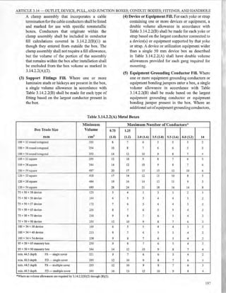


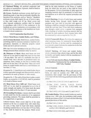


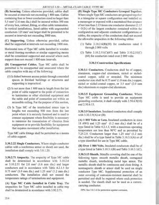


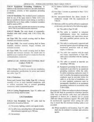


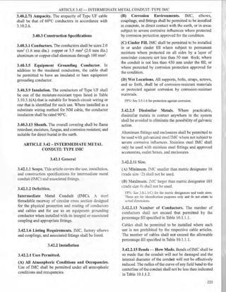


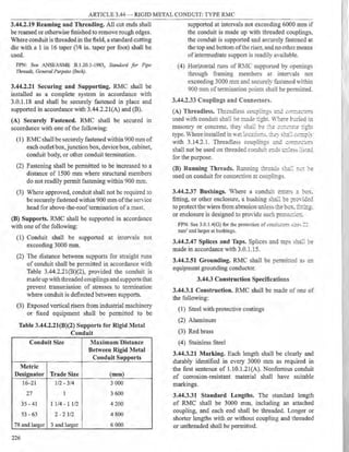
![ARTICLE 3.48 ~ FLEXIBLE METAL CONDUIT: TYPE FMC
ARTICLE 3.48 - FLEXIBLE METAL CONDUIT: 3.48.2.11 Size.
TYPE FMC
3.48.1 General
3.48.1.1 Scope. This article covers the use, installation,
and construction specifications for flexible metal
conduit (FMC) and associated fittings.
3.48.1.2 Definition.
Flexible Metal Conduit (FMC). A raceway of circular
cross section made of helically wound, formed,
in~erlocked metal strip.
3.48.1.6 Listing Requirements. FMC and associated
fittings shall be listed.
3.48.2 Installation
3.48.2.1 Uses Permitted. FMC shall be permitted to be
used in exposed and concealed locations.
3.48.2.3 Uses Not Permitted. FMC shall not be used in
the following:
(1) In wet locations
(2) In hoistways, other than as permirted m
6.20.3.l(A)(l)
(3) In storage battery rooms
(4) In any hazardous (classified. loca:.on excey: as
permined by other anic es i:J. Ihis Code
(5) Where exposedto mater12:s :J.a'<ing a de~criorating
effec on the in.srarec concuctors. s::ch as oil or
gasoline
(6) L"nderground or embeu ~ eJ ir:. poured c ncrete or
aggrega-e
(7) Where subject .o physical damage
(A) Minimum. FMC less than metric designator 16
mm (trade size 1/2) shall not be used unless permitted
in 3.48.2.2l(A)(l) through (A)(5) for metric designator
12 mm (trade size 3/8).
(1) For enclosing the leads of motors as permitted in
4.30. l 3.5(B)
(2) In lengths not in excess of 1800 mm for any ofthe
following uses:
a. For utilization equipment
b. As part of a listed assembly
c. For tap connections to luminaires as permitted
in -U 0.10.8(C)
(3) For manufactured wiring systems as permitted in
6.-U.lOO(A)
(-+) In hoisrn·ays as permitted in 6.20.3 .1 (A)(l)
(:51 As pan of a listed assembly to connect wired
luminaire se"tions as permitted in 4.10.12.8(C)
(B) :Iaximum. F1C larger than metrie designator 103
mm (trade size 3.8) shall not be used.
FP::s;-: s~ 3.0.1.l(C) for the metric designators and trade sizes.
Tcese are for identificarion purposes only and do not relate to
acn:al <liinensions.
3.48.2.13 ~umber of Conductors. The number
of conductors shall not exceed that permitted by
the percentage fill specified in Table 10.1.1.1, or as
permitted in Table 3.48.2.13, or for metric designator
12 (trade size 3/8).
Cables shall be permitted to be installed where such
use is not prohibited by the respective cable articles.
The number of cables shall not exceed the allowable
percentage fill specified in Table 10.1.1.1.
Table 3.48.2.13 :Ia:x.in::mm ~umber of Insulated Conductors in Metric Designator 12 (Trade Size 'lS) Flexible
Metal Conduit (FMC)
Types TF, XHHW, Types TFN, Types FEP, FEBP,
Types RFH-2, SF-2 TW THHN, THWN PF, PGF
Fittings Fittings Fittings Fittings Fittings Fittings Fittings Fittings
Inside Outside Inside Outside Inside Outside Inside Outside
Size [ mm2 (mm dia.)] Conduit Conduit Conduit Conduit Conduit Conduit Conduit Conduit
0.75(1.0) 2 3 3 5 5 8 5 8
1.25(1.2) 1 2 " 4 4 6 4 6
:)
2.0(1.6) 1 2 2 3 3 4 3 4
3.5(2.0) - - I 2 2 3 2 3
5.5(2.6) - - 1 1 1 I 1 2
'
*In add1t1on, one covered or bare eqmpment groundmg conductor of the same size shall be permitted.
227](https://image.slidesharecdn.com/pec2017part1-241003060423-f7360a96/85/Philllipine-electrical-code-2017-PART-1-pdf-250-320.jpg)
![ARTICLE 3.50 - LIQUIDTIGHT FLEXIBLE METAL CONDUIT: TYPE LFMC
3.48.2.15 Bends - How Made. Bends in conduit 3.48.2.33 Couplings and Connectors.
shall be made so that the conduit is not damaged and connectors shall not be concealed.
the internal diameter of the conduit is not effectively
reduced. Bends shall be permitted to be made manually
without auxiliary equipment. The radius of the curve to
the centerline of any bend shall not be less than shown
in Table 10.1.1.2 using the column "Other Bends."
3.48.2.17 Bends - Number in One Run. There shall
not be more than the equivalent of four quarter bends
(360 degrees total) between pull points. for example,
conduit bodies and boxes.
3.48.2.19 Trimming. All cut ends shall be trimmed
or otherwise finished to remove rough edges, except
where fittings that thread into the convolutions are used.
3.48.2.21 Securing and Supporting. Ftv1C shall be
securely fastened in place and supported in accordance
with 3.48.2.21(A) and (B).
(A) Securely Fastened. FMC shall be securely fastened
in place by an approved means Vithin 300 mm of each
box, cabinet, conduit body, or other conduit termination
and shall be supported and secured at inten-als not to
exceed 1 400 mm. Where used, cable ties shall be listed
and be identified for securcment and support.
Exception No. 1: Where FMC is fished het1t·een access
points through concealed spaces in finished buildings
or structures and supporting is impracticable.
Exception No. 2: Where flexibility is necessary after
installation, lengths from rhe last point where the raceway is
securelyfastened shall not exceed thefollowing:
(1) 900 mm for metric designators 16 through 35
(trade sizes 1,/2 through J1!4)
(2) 1200 mm for metric designators 41 through 53
(trade sizes ]1,/2 through 2)
(3) 1500 mm for metric designators 63 (trade si::e
21
/2) and larger
Exception No. 3: Lengths not exceeding 1 800 mm.from
a luminaire terminal connection for tap connections to
luminaires as permitted in 4.10. I0.8(C).
Exception No. 4: Lengths not exceeding 1 800 mm.from
the last point where the raceway is secure(v fastened
for connections within an accessible ceilin~ to a
luminaire(s) or other equipment. For the purposes of
this exception, listed.flexible metal conduit.fittings shall
be permitted as a means ofsecurement and support.
(B) Supports. Horizontal runs of FMC supported by
openings through framing members at intervals not
greater than 1400 mm and securely fastened within 300
mm of termination points shall be pennitted.
228
3.48.2.47 Splices and Taps. Splices and taps shall be
made in accordance with 3.0.1.15.
3.48.2.51 Grounding and Bonding. If used to connect
equipment where flexibility is necessary to minimize the
transmission of vibration from equipment or to pro'ide
flexibility for equipment that requires movement after
installation, an equipment grounding conductor shall be
installed.
Where flexibility is not required after installation,
FMC shall be permitted to be used as an equipment
grounding conductor when installed in accordance with
2.50.6.9(5).
Where required or installed, equipment grounding
conductors shall be installed in accordance with
2.50.7.5(8).
Where required or installed, equipment bonding
jumpers shall be installed in accordance with 2.50.5.13.
ARTICLE 3.50 - LIQUIDTIGHT FLEXIBLE
METAL CONDUIT: TYPE LFMC
3.50.1 General
3.50.1.1 Scope. This article covers the use, installation,
and construction specifications for liquidtight flexible
metal conduit (LFMC) and associated fittings.
3.50.1.2 Definition.
Liquidtight Flexible Metal Conduit (LFMC). A
raceway of circular cross section having an outer
liquidtight, nonmetallic, sunlight-resistant jacket over
an inner flexible metal core with associated couplings,
connectors, and fittings for the installation of electric
conductors.
3.50.1.6 Listing Requirements. LFMC and associated
fittings shall be listed.
3.50.2 Installation
3.50.2.1 Uses Permitted. LFMC shall be permitted to
be used in exposed or concealed locations as follows:
(1) Where conditions of installation, operation. or
maintenance require flexibility or protection from
liquids, vapors, or solids
(2) In hazardous (classified) locations where
specifically permitted by Chapter 5.
(3) For direct burial where listed and marked for,!::.;:
purpose](https://image.slidesharecdn.com/pec2017part1-241003060423-f7360a96/85/Philllipine-electrical-code-2017-PART-1-pdf-251-320.jpg)
![ARTICLE 3.50 -- LIQUIDTIGHT FLEXIBLE METAL CONDUIT: TYPE LFMC
3.50.2.1 Uses Not Permitted. LFMC shall not be used
as follows:
(1) Where subject to physical damage
(2) Where any combination ofambient and conductor
temperature produces an operating temperature in
excess of that for which the material is approved
3.50.2.ll Size.
(A) Minimum. LFMC smaller than metric designator
16 (trade size 12) shall not be used.
Exception: LFMC of metric designator 12 (trade si::e
-Y8) shall be pemzitted as covered in 3.48.2.11(A).
(B) :fax:imum. The maximum size of LFMC shall be
m~tric designator 103 (trade size 4).
FP};": See 3.0.l.l(Cl for the metric designators and trade sizes.
These are for identification purposes only and do not relate to
acrual dimensions.
3.50.2.13 Number of Conductors or Cables.
(A) Metric Designators 16 through 103 (Trade Sizes
'l2 through 4). The number of conductors shall not
exceed that pem1itted by the percentage fill specified in
Table 10.1.1.1.
Cables shall be pe1mitted to be installed where such
use is not prohibited by the respective cable articles.
The number of cables shall not exceed the allowable
percentage fill specified in Table 10.1.1.1.
(B) Metric Designator 12 (Trade Size 18). The number
of conductors shall not exceed that permitted in Table
3.48.2.13, "Fittings Outside Conduit" columns.
3.50.2.15 Bends - How Made. Bends in conduit shall
be so made that the conduit will not be damaged and the
internal diameter of the conduit will not be effectively
reduced. Bends shall be permitted to be made manually
without auxiliary equipment. The radius ofthe curve to
the centerline ofany bend shall not be less than required
in Table 10.1.1.2 using the colunm "Other Bends."
3.50.2.17 Bends - Number in One Run. There shall
not be more than the equivalent of four quarter bends
(360 degrees total) between pull points, for example,
conduit bodies and boxes.
3.50.2.19 Trimming. All cut ends of conduit shall be
:rimmed inside and outside to remove rough edges.
3.50.2.21 Securing and Supporting. LFMC shall be
~curely fastened in place and supported in accordance
i!h 3.50.2.2l(A) and (B).
(A) Securely Fastened. LFMC shall be securely
fastened in place by an approved means within 300 mm
of each box, cabinet, conduit body, or other conduit
tern1ination and shall he supported and secured at
intervals not to exceed l 400 mm. Where used, cable
ties shall be listed and be identified for sccuremcnt and
support.
Exception No. 1: Where LFlWC isfished between access
points through concealed spaces in finished huildings
or structures and supporting is impractical.
Exception No. 2: Where flexibility is necessmy after
installation, lengths from the last point where the raceway
is sernre(rfastened shall not exceed thefollo-wing:
(1) 900 mm for metric designators 16 through 35
(trade .stes '12 through Jl/4)
(2) 1]00 mm for metric designators 41 through 53
(trade si::es 1:/:! through 2)
(3) 1500 mrn for metric designators 63 (trade size
2112) and larger
Exception No. 3.- Lengths not exceeding 1800 mm.from
a luminaire terminal connection for tap conductors to
lwninaires, as pennitted in 4.10.10.8(C).
Exception No. 4: Lengths not exceeding 1 800 mm.from
the lastpoint where the raceway is secureZrfastenedfor
connections within an accessihle ceiling to lwninaire(.<;)
or other equipment. For the purposes of 3.50.2.21,
listed LFMC fittings shall be pennitted as a means of
securement and support.
(B) Supports. Horizontal runs of LFMC supported by
openings through framing members at intervals not
greater than 1400 mm and securely fastened within 300
mm oftermination points shall be permitted.
3.50.2.33 Couplings and Connectors. Only fittings
listed for use with LFMC shall be used. Angle connectors
shall not be concealed. Straight LFMC fittings shall be
permitted for direct burial where marked.
3.50.2.47 Splices and Taps. Splices and taps shall be
made in accordance with 3.0.1.15.
3.50.2.51 Grounding and Bonding. Ifused to connect
equipment where flexibility is necessary to minimize the
transmission of vibration from equipment or to provide
flexibility for equipment that requires movement after
installation. an equipment grounding conductor shall be
installed.
Where flexibility is not required after installation,
LFMC shall be permitted to be used as an equipment
grounding conductor when installed in accordance with
2.50.6.9(6).
229](https://image.slidesharecdn.com/pec2017part1-241003060423-f7360a96/85/Philllipine-electrical-code-2017-PART-1-pdf-252-320.jpg)


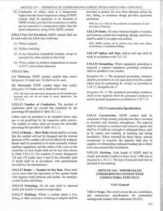
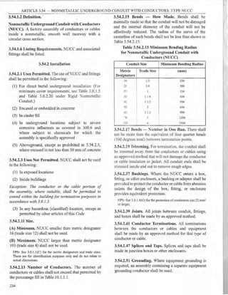
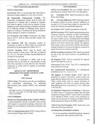

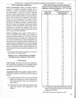
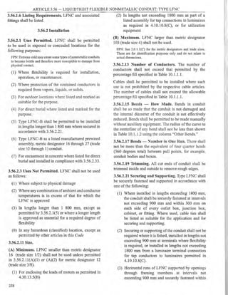
![ARTICLE 3.58 - ELECTRICAL METALLIC TUBING: TYPE EMT
300 mm oftennination points shall be permitted.
(4) Securing or supporting of LFNC shall not be
required where installed in lengths not exceeding
1 800 mm from the last point where the raceway
is securely fastened for connections vithin an
accessible ceiling to a luminaire(s) or other
equipment. For the purpose of 3.56.2.21, listed
liquidtight flexible nonmetallic conduit fittings
shall be permitted as a means of support.
3.56.2.33 Couplings and Connectors. Only fittings
listed for use with LFNC shall be used. Angle connectors
shall not be used for concealed raceway installations.
Straight LFNC fittings are permitted for direct burial or
encasement in concrete.
3.56.2.47 Splices and Taps. Splices and taps shall be
made in accordance with 3.0.1.15.
3.56.2.51 Grounding. Where equipment grounding is
required, a separate equipment grounding conductor
shall be installed in the conduit.
Exception No. ]: As permitted in 2.50. 7.5(B), Exception
No. 2, for de circuits and 2.50. 7.5(B), Exception No.
J,for separateZv run equipment grounding conductors.
Exception No. 2: Where the grounded conductor is used
to ground equipment as permitted in 2.50. 7. J3.
3.56.3 Construction Specifications
3.56.3.1 Construction. lf:'C-B as a prewired
manufacrured assembly sha:I be pro1.-ided in continuous
lengths capable o!'bcing shippedin a coil reel. or carton
,,-ithout damage~
3.56.3.21 :larking. LFC shall be marked at least
eYery 600 ::-11B in a::cordance with 1.10.1.21. The
marking shall i::.:i rde a Iype designation in accordance
with 356..2 and -he rrade size. Conduit that is intended
for outdoor se or direct burial shall be marked.
The type_ size. and quantity of conductors used in
prewired manufactured assemblies shall be identified
by means of a printed rag or label attached to each end
of the manufactured assembly and either the carton,
coil. or reel. Tue enclosed conductors shall be marked
in accordance ,·ith 3.10.3.17.
ARTICLE 3.58 - ELECTRICAL METALLIC
TUBI~G: TYPE EMT
3.58.1 General
3.58.1.1 Scope. This article covers the use, installation,
and construction specifications for electrical metallic
tubing (EMT) and associated fittings.
3.58.1.2 Definition.
Electrical Metallic Tubing (EMT). An unthreaded
thin-wall raceway of circular cross section designed
for the physical protection and routing of conductors
and cables and for use as an equipment grounding
conductor when installed utilizing appropriate fittings.
EMT is generally made ofsteel (ferrous) Vith protective
coatings or aluminum (nonferrous).
3.58.1.6 Listing Requirements. EMT, factory elbows,
and associated fittings shall be listed.
3.58.2 Installation
3.58.2.1 Uses Permitted.
(A) Exposed and Concealed. The use of EMT shall be
permitted for both exposed and concealed work for the
following:
(1) In concrete, in direct contact with the earth or in
areas subject to severe corrosive influences where
installed in accordance with 3.58.2.l(B)
(2) In dry, damp, and wet locations
(3) In any hazardous (c.lassified) location as permitted
by other articles in this Code
(B) Corrosiw EnYironments.
(1) GalYanized Steel and Stainless Steel EMT,
Elbows. and Fittings. Galvanized steel and
stainless steel EfT. elbows, and fittings shall
be permitted to be installed in concrete, in direct
contact with the earth, or in areas subject to
severe corrosive influences where protected by
corrosion protection and approved as suitable for
the condition.
(2) Supplementary Protection ofAluminum EMT.
Aluminum EMT shall be provided with approved
supplementary corrosion protection where
encased in concrete or in direct contact with the
earth.
(C) Cinder Fill. Galvanized steel and stainless steel
EMT shall be permitted to be installed in cinder concrete
or cinder fill where subject to permanent moisture when
protected on all sides by a layer of noncinder concrete
at least 50 mm thick or when the tubing is installed at
least 450 mm under the fill.
(D) Wet Locations. All supports, bolts, straps, screws,
and so forth shall be of corrosion-resistant materials
or protected against corrosion by corrosion-resistant
materials.
FPN: See 3.0.1.6 for protection against corrosion.
239](https://image.slidesharecdn.com/pec2017part1-241003060423-f7360a96/85/Philllipine-electrical-code-2017-PART-1-pdf-262-320.jpg)