Download to read offline


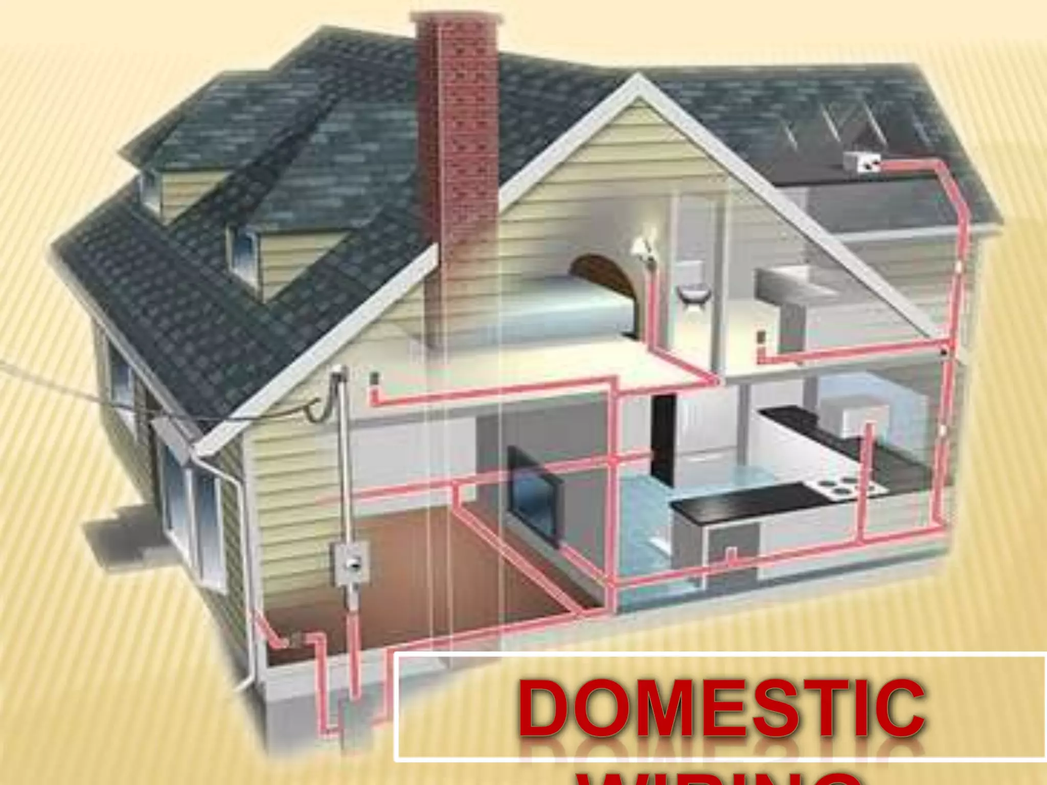


This document provides information on electrical wiring for domestic and industrial applications. It discusses different types of domestic wiring such as cleat wiring, CTS wiring, metal sheathed wiring, and conduit wiring. It also covers factors to consider when choosing wiring such as durability, safety, cost and accessibility. The document then discusses industrial wiring requirements including color coding, splices, panel wiring, machine wiring and wire connectors. It concludes by describing common wire forms like solid, stranded and braided wires.