Electrical installation and wiring for house wirings
1.
May, 2025
Practical Trainingfor the Military Professionals
Title :-Basic Components of Electrical Installations and
Electric wiring
Prepared by:- ABDURO G.
May,2025
3.
TRAINING OUT LINE
Introduction to Electrical Installations
Conductors and Cables
Basic components Electrical Circuits
Electrical Symbols and Wiring Diagrams
Wiring Systems
Wiring Accessories
Distribution Boards and Switchboards
Electrical Safety
Electrical Protection Devices
Lighting and Fixtures
Earthings System
Electrical Installation and Testing
4.
ELECTRICAL INSTALLATION
isthe process of installing and maintaining electrical
systems and equipment. I
t may include tasks such as installing wiring, repairing or
replacing damaged equipment, and inspecting
electrical systems for safety.
6.
Resistance
The higherthe resistance, the lower the current flow. If
abnormally high, one possible cause (among many) could
be damaged conductors due to burning or corrosion. All
conductors give off some degree of heat, so overheating is
an issue often associated with resistance.
The lower the resistance, the higher the current flow.
Possible causes: insulators damaged by moisture or
overheating.
Ampere
Base unitof electric current in
the International System of
Units (SI). It is named after André-
Marie Ampère (1775–1836),
An ampere is the unit used to
measure electric current. Current
is a count of the number of
electrons flowing through a circuit.
How fast an electric current flows
is an example of an ampere.
9.
Watt
The basic unitof
electric, Unit of power
(W)
The watt is a measure of
how much power is
released
Power consumed
Solid Wire
Asingle conductor
that is either bare
or insulated by a
protective colored
sheath. It offers
low resistance and
are perfect for use
in higher
frequencies
16.
Stranded Wire
Strandedwires are used where flexibility is important
because which the wire can be used for a longer period.
This type of wire have larger cross-sectional area than solid
wires for the same current carrying capacity.
Stranded Wire
Sizeof Wires - Each
application requires
a certain wire size
for installation, and
the right size for a
specific application
is determined by
the wire gauge
19.
Stranded Wire
WireLettering – The letters THHN, THWN, THW and XHHN
represent the main insulation types of individual wires. These
letters depict the following NEC requirements:.
T – Thermoplastic insulation
H – Heat resistance
HH – High heat resistance (up to 194°F)
W – Suitable for wet locations
N – Nylon coating, resistant to damage by oil or gas
X – Synthetic polymer that is flame-resistant
20.
Main Feeder Wires
MainFeeder Wires : Main power feeder
wires are the wires that connect the
service weather head to the house.
They’re made with stranded or solid THHN
wire and the cable installed is 25% more
than the load required.
Panel Feed Wires
PanelFeed Wires : Panel feed cables are
generally black insulated wire. These are used
to power the main junction box and the circuit
breaker panels. Just like main power feeder
wires, the cables should be rated for 25% more
than the actual load.
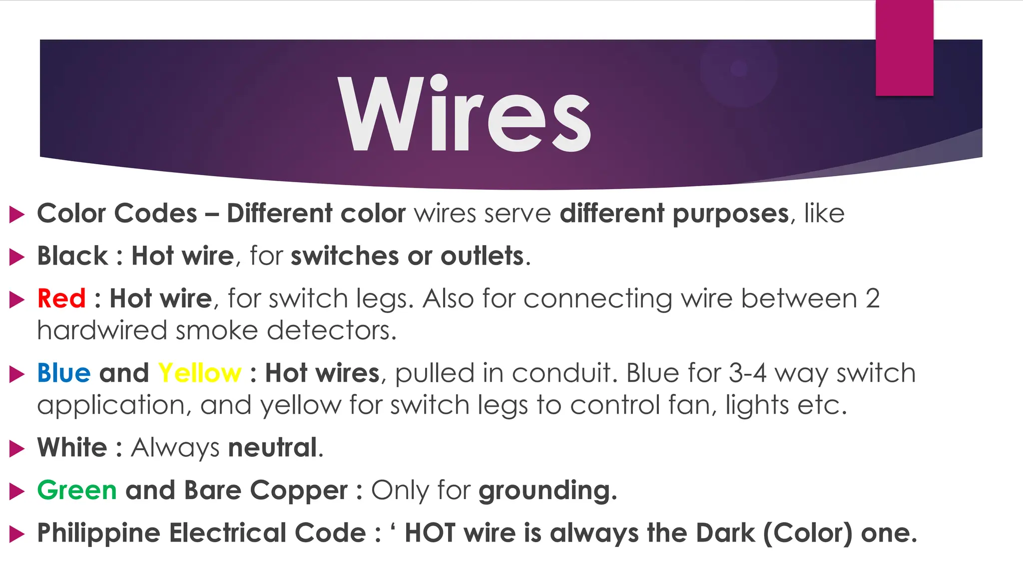
Wires
Color Codes– Different color wires serve different purposes, like
Black : Hot wire, for switches or outlets.
Red : Hot wire, for switch legs. Also for connecting wire between 2
hardwired smoke detectors.
Blue and Yellow : Hot wires, pulled in conduit. Blue for 3-4 way switch
application, and yellow for switch legs to control fan, lights etc.
White : Always neutral.
Green and Bare Copper : Only for grounding.
Philippine Electrical Code : ‘ HOT wire is always the Dark (Color) one.
27.
Cable
Wire is asingle
electrical
conductor,
whereas a
cable is a group
of wires swathed
in sheathing.
Accessories of ElectricalInstallation
All the wiring systems and electrical installations needs the
following accessories:
1. Cables 2. Flexible wires
3. Switches 4. Fuses
5. Ceiling rose 6. Lamp holders
7. Plugs 8. Socket outlets
9. Junction boxes
33.
Wiring Diagrams
Awiring diagram is a simple visual representation of the physical
connections and physical layout of an electrical system or circuit.
It shows how the electrical wires are interconnected and can also
show where fixtures and components may be connected to the
system.
Splices & Joints
Theconnections must be well made and the wires
tightly joined to prevent a loss of voltage to the
device powered. In high current situations a poor
connection causes heat at the connection and
oxidiation of the wires and no more or intermittent
connections.
Most problems in electrical is not a short but: an
open connection.
37.
Kinds of Splices
WesternUnion Splice
Tap joint
Fixture splices, or fixture joints
Rat-tail splice, Twist splice, Pig-tail splice
Britannia Splice
A Through Fixture joint
Wrapped Tap
38.
Western Union Splice
This is the most widely used
splice or joint in interior
wiring installation to
extend the length of wire
from one point to another.
Used extensively for
outside wiring to extend
the length of wire from one
end to another.
39.
Tap splice orTap joint
This is used
where the
tap wire is
under
considerable
tensile stress
circuit
Rat-tail splice/Twist splice/Pig-tailsplice
commonly used to join two
or more • conductors inside
the junction box. It is •
suitable for service where
there is no • mechanical
stress when wires are to be
• connected in an outlet
box, switch, or • conduit
fitting