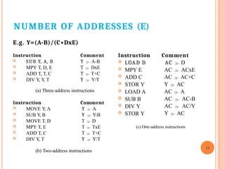
Adama Science and Technology University
College of Electrical Engineering and Computing
Department of Electronics and Communication Engineering
Course: Computer Architecture and Organization
Course Instructor: Gemechu Dinkisa ( M.S.c)
Email: gammedinqisaa@gmail.com
CHAPTER ONE
CENTRAL PROCESSING UNIT
2
Contents
3.1 Instruction sets
3.2 Instruction format and addressing modes
3.3 RISC and CISC
3.4 CPU Structure
3.5 The Control Unit (Hardwired and Micro programmed )
3.6 Basic computer Design
PART I ( 3.1)
Instruction Sets
MACHINE
INSTRUCTION
3
 Machine instructions
instructions are codes
computer /machine.
or computer
executed by
 An Instruction Set is the complete collection of
commands (instructions) that a processor is
capable of executing.
 Each instruction specifies the operation to be
performed and provides the necessary.
ELEMENTS OF A MACHINE
INSTRUCTION
o Operation code(Opcode)
o The Opcode is the part of an instruction that specifies the
operation to be performed.
o e.g., ADD, SUB, IN, OUT….
o Each operation is represented by a unique (opcode), which
the processor decodes to execute the instruction.
o Source operand reference
o The operation may involve one or more source operands
o are inputs for the operation
o Result operand reference
o Operand for result produced from operation
o Are output of the operation
o Next instruction reference
o Tells the processor where to fetch the next instruction
4
SOURCE AND RESULT
OPERANDS
 Immediate
⚫ The value of the operand is contained in a field in
the instruction being executed
 Processor register
⚫ A processor contains one or more registers that may be
referenced by machine instructions.
 Main or virtual memory
⚫ As with next instruction references, the main or virtual
memory address must be supplied
 I/O device
⚫ The instruction must specify the I/O module and device for
the operation.
⚫ If memory-mapped I/O is used, this is just another mai5
n or
virtual memory address
INSTRUCTION
REPRESENTATION
 Within the computer each instruction is
represented by a sequence of bits
 The instruction is divided into fields,
corresponding to the constituent elements of
the instruction
Opcode Operand Reference Operand Reference
16 bits 6
4 bits 6 bits 6 bits
INSTRUCTION
REPRESENTATION
⚫ ADD A,B  0000 0001 1000 0000 1000 1010 7
 Opcodes are represented by abbreviations -
mnemonics
 Examples:
⚫ ADD
⚫ SUB
⚫ MUL
⚫ DIV
⚫ LOAD
⚫ STOR
Add
Subtract
Multiply
Divide
Load data from memory
Store data to memory
 Operands can also be represented in this way
NUMBER OF ADDRESSES (A)
8
 3 addresses
⚫ Result, Operand 1, Operand 2
⚫ a = b + c;
⚫ Needs very long words to hold everything
⚫ E.g. ADD A, B, C ; store result of B + C in A
NUMBER OF ADDRESSES (B)
9
2 addresses
⚫ One address doubles as operand and result
⚫ a = a + b
⚫ Reduces length of instruction
⚫ Requires some extra workl
 Temporary storage to hold some results
⚫ E.g. ADD A, B ; store result of A+B in A
NUMBER OF ADDRESSES (C)
⚫ E.g. ADD B ; add B and Acc result on Acc.
10
 1 address
⚫ Implicit second address
⚫ Usually a dedicated register (called
accumulator)
⚫ Common on early machines (when memory was
scarce)
NUMBER OF ADDRESSES (D)
 0 (zero) addresses
⚫ All addresses implicit
⚫ Uses a stack
⚫ e.g.
push a
push b
add
pop c
c = a +
b
11
…
1234
5678
b
a
c
NUMBER OF ADDRESSES (E)
E.g. Y=(A-B)/(C+DxE)
Instruction Comment
Y  A-B
T  DxE
T  T+C
Y  Y/T
 SUB Y, A, B
 MPY T, D, E
 ADD T, T, C
 DIV Y
, Y
, T
(a) Three-address instructions
Instruction Comment
Y  A
Y  Y-B
T  D
T  TxE
T  T+C
Y  Y/T
 MOVE Y
, A
 SUB Y
, B
 MOVE T, D
 MPY T, E
 ADD T, C
 DIV Y
, T
(b) Two-address instructions
12
Instruction Comment
AC  D
AC  ACxE
AC  AC+C
Y  AC
AC  A
AC  AC-B
AC  AC/Y
Y  AC
 LOAD D
 MPY E
 ADD C
 STOR Y
 LOAD A
 SUB B
 DIV Y
 STOR Y
(c) One-address instructions
NUMBER OF ADDRESSES IN
INSTRUCTIONS
More addresses
⚫ More complex instructions
⚫ More registers
 Inter-register operations are quicker
⚫ Fewer instructions per program
Fewer addresses
⚫ Less complex instructions
⚫ More instructions per program (more complex programs
and longer total execution time)
⚫ Faster fetch/execution of individual instructions
13
INSTRUCTION SET DESIGN
Fundamental design issues
 Operation repertoire
⚫ How many operation?
⚫ What can they do?
⚫ How complex are they?
 Data types
⚫ Data type supported by
the instruction
 Instruction formats
⚫ Length (in bits) of op
code field
⚫ Number of addresses
⚫ Variable length
TYPES OF OPERAND
Machine instructions operate on data
The most important general categories of
data are
⚫Numbers
 Integer or fixed point
 floating point
 Decimal(BCD)
⚫Characters
is text or character strings
 ASCII etc.
⚫Logical Data
 Bits or flags
⚫Addresses
15
INSTRUCTION
TYPES
 Data processing: Arithmetic and logic instructions
⚫ Arithmetic instructions provide computational
capabilities for processing numeric data
⚫ Logic (Boolean) instructions operate on the bits of a
word
 Data storage: Movement of data into or out of register
and or memory locations
 Data movement: I/O instructions
 Control: Test and branch instructions
⚫ Test instructions are used to test the value of a data word
TYPES OF OPERATION
17
 Data Transfer
 Arithmetic
 Logical
 Conversion
 I/O
 System Control
 Transfer of Control
DATA TRANSFER
18
 Specify
⚫ Source
⚫ Destination
⚫ Amount of data
 May be different instructions for different movements
⚫ e.g. IBM 370
 One instruction and different addresses
⚫ e.g. VAX
Operation
Mnemonic Name
Number of Bits
Transferred Description
L Load 32 Transfer from memory to register
LH Load Halfword 16 Transfer from memory to register
LR Load 32 Transfer from register to register
LER Load (Short) 32 Transfer from floating-point register to
floating-point register
LE Load (Short) 32 Transfer from memory to floating-point
register
LDR Load (Long) 64 Transfer from floating-point register to
floating-point register
LD Load (Long) 64 Transfer from memory to floating-point
register
ST Store 32 Transfer from register to memory
STH Store Halfword 16 Transfer from register to memory
STC Store Character 8 Transfer from register to memory
STE Store (Short) 32 Transfer from floating-point register to
memory
STD Store (Long) 64 Transfer from floating-point register to
memory
Table 12.5
Examples of IBM EAS/390 Data Transfer Operations
(Table can be found on page 428 in textbook.)
19
ARITHMETIC
20
 Add, Subtract, Multiply, Divide
 Signed Integer
 Floating point
 May include
⚫ Increment (a++)
⚫ Decrement (a--)
⚫ Negate (-a)
⚫ Absolute value
LOGICAL
 Bitwise operations
 AND, OR, NOT
CONVERSION
 E.g. Binary to Decimal
INPUT/OUTPUT
21
 Variety of approaches taken:
⚫ Isolated programmed I/O
⚫ Memory-mapped programmed I/O
⚫ DMA
⚫ Use of an I/O processor
SYSTEMS
CONTROL
 Privileged instructions
 CPU needs to be in specific state
⚫ Ring 0 on 80386+
⚫ Kernel mode
 For operating systems use
 Examples:
⚫ A system control instruction may read or alter a control
register
⚫ An instruction to read or modify a storage protection key
24
TRANSFER OF CONTROL
23
 Branch
⚫ e.g. branch to x if result is zero
 Skip
⚫ e.g. increment and skip if zero
⚫ ISZ Register1
⚫ Branch xxxx
⚫ ADD A
 Subroutine call
⚫ c.f. interrupt call
THANK YOU
ANY QUESTION?
24

Chapter 3 CPU is about central processing

  • 1.
    Adama Science andTechnology University College of Electrical Engineering and Computing Department of Electronics and Communication Engineering Course: Computer Architecture and Organization Course Instructor: Gemechu Dinkisa ( M.S.c) Email: gammedinqisaa@gmail.com
  • 2.
    CHAPTER ONE CENTRAL PROCESSINGUNIT 2 Contents 3.1 Instruction sets 3.2 Instruction format and addressing modes 3.3 RISC and CISC 3.4 CPU Structure 3.5 The Control Unit (Hardwired and Micro programmed ) 3.6 Basic computer Design PART I ( 3.1) Instruction Sets
  • 3.
    MACHINE INSTRUCTION 3  Machine instructions instructionsare codes computer /machine. or computer executed by  An Instruction Set is the complete collection of commands (instructions) that a processor is capable of executing.  Each instruction specifies the operation to be performed and provides the necessary.
  • 4.
    ELEMENTS OF AMACHINE INSTRUCTION o Operation code(Opcode) o The Opcode is the part of an instruction that specifies the operation to be performed. o e.g., ADD, SUB, IN, OUT…. o Each operation is represented by a unique (opcode), which the processor decodes to execute the instruction. o Source operand reference o The operation may involve one or more source operands o are inputs for the operation o Result operand reference o Operand for result produced from operation o Are output of the operation o Next instruction reference o Tells the processor where to fetch the next instruction 4
  • 5.
    SOURCE AND RESULT OPERANDS Immediate ⚫ The value of the operand is contained in a field in the instruction being executed  Processor register ⚫ A processor contains one or more registers that may be referenced by machine instructions.  Main or virtual memory ⚫ As with next instruction references, the main or virtual memory address must be supplied  I/O device ⚫ The instruction must specify the I/O module and device for the operation. ⚫ If memory-mapped I/O is used, this is just another mai5 n or virtual memory address
  • 6.
    INSTRUCTION REPRESENTATION  Within thecomputer each instruction is represented by a sequence of bits  The instruction is divided into fields, corresponding to the constituent elements of the instruction Opcode Operand Reference Operand Reference 16 bits 6 4 bits 6 bits 6 bits
  • 7.
    INSTRUCTION REPRESENTATION ⚫ ADD A,B 0000 0001 1000 0000 1000 1010 7  Opcodes are represented by abbreviations - mnemonics  Examples: ⚫ ADD ⚫ SUB ⚫ MUL ⚫ DIV ⚫ LOAD ⚫ STOR Add Subtract Multiply Divide Load data from memory Store data to memory  Operands can also be represented in this way
  • 8.
    NUMBER OF ADDRESSES(A) 8  3 addresses ⚫ Result, Operand 1, Operand 2 ⚫ a = b + c; ⚫ Needs very long words to hold everything ⚫ E.g. ADD A, B, C ; store result of B + C in A
  • 9.
    NUMBER OF ADDRESSES(B) 9 2 addresses ⚫ One address doubles as operand and result ⚫ a = a + b ⚫ Reduces length of instruction ⚫ Requires some extra workl  Temporary storage to hold some results ⚫ E.g. ADD A, B ; store result of A+B in A
  • 10.
    NUMBER OF ADDRESSES(C) ⚫ E.g. ADD B ; add B and Acc result on Acc. 10  1 address ⚫ Implicit second address ⚫ Usually a dedicated register (called accumulator) ⚫ Common on early machines (when memory was scarce)
  • 11.
    NUMBER OF ADDRESSES(D)  0 (zero) addresses ⚫ All addresses implicit ⚫ Uses a stack ⚫ e.g. push a push b add pop c c = a + b 11 … 1234 5678 b a c
  • 12.
    NUMBER OF ADDRESSES(E) E.g. Y=(A-B)/(C+DxE) Instruction Comment Y  A-B T  DxE T  T+C Y  Y/T  SUB Y, A, B  MPY T, D, E  ADD T, T, C  DIV Y , Y , T (a) Three-address instructions Instruction Comment Y  A Y  Y-B T  D T  TxE T  T+C Y  Y/T  MOVE Y , A  SUB Y , B  MOVE T, D  MPY T, E  ADD T, C  DIV Y , T (b) Two-address instructions 12 Instruction Comment AC  D AC  ACxE AC  AC+C Y  AC AC  A AC  AC-B AC  AC/Y Y  AC  LOAD D  MPY E  ADD C  STOR Y  LOAD A  SUB B  DIV Y  STOR Y (c) One-address instructions
  • 13.
    NUMBER OF ADDRESSESIN INSTRUCTIONS More addresses ⚫ More complex instructions ⚫ More registers  Inter-register operations are quicker ⚫ Fewer instructions per program Fewer addresses ⚫ Less complex instructions ⚫ More instructions per program (more complex programs and longer total execution time) ⚫ Faster fetch/execution of individual instructions 13
  • 14.
    INSTRUCTION SET DESIGN Fundamentaldesign issues  Operation repertoire ⚫ How many operation? ⚫ What can they do? ⚫ How complex are they?  Data types ⚫ Data type supported by the instruction  Instruction formats ⚫ Length (in bits) of op code field ⚫ Number of addresses ⚫ Variable length
  • 15.
    TYPES OF OPERAND Machineinstructions operate on data The most important general categories of data are ⚫Numbers  Integer or fixed point  floating point  Decimal(BCD) ⚫Characters is text or character strings  ASCII etc. ⚫Logical Data  Bits or flags ⚫Addresses 15
  • 16.
    INSTRUCTION TYPES  Data processing:Arithmetic and logic instructions ⚫ Arithmetic instructions provide computational capabilities for processing numeric data ⚫ Logic (Boolean) instructions operate on the bits of a word  Data storage: Movement of data into or out of register and or memory locations  Data movement: I/O instructions  Control: Test and branch instructions ⚫ Test instructions are used to test the value of a data word
  • 17.
    TYPES OF OPERATION 17 Data Transfer  Arithmetic  Logical  Conversion  I/O  System Control  Transfer of Control
  • 18.
    DATA TRANSFER 18  Specify ⚫Source ⚫ Destination ⚫ Amount of data  May be different instructions for different movements ⚫ e.g. IBM 370  One instruction and different addresses ⚫ e.g. VAX
  • 19.
    Operation Mnemonic Name Number ofBits Transferred Description L Load 32 Transfer from memory to register LH Load Halfword 16 Transfer from memory to register LR Load 32 Transfer from register to register LER Load (Short) 32 Transfer from floating-point register to floating-point register LE Load (Short) 32 Transfer from memory to floating-point register LDR Load (Long) 64 Transfer from floating-point register to floating-point register LD Load (Long) 64 Transfer from memory to floating-point register ST Store 32 Transfer from register to memory STH Store Halfword 16 Transfer from register to memory STC Store Character 8 Transfer from register to memory STE Store (Short) 32 Transfer from floating-point register to memory STD Store (Long) 64 Transfer from floating-point register to memory Table 12.5 Examples of IBM EAS/390 Data Transfer Operations (Table can be found on page 428 in textbook.) 19
  • 20.
    ARITHMETIC 20  Add, Subtract,Multiply, Divide  Signed Integer  Floating point  May include ⚫ Increment (a++) ⚫ Decrement (a--) ⚫ Negate (-a) ⚫ Absolute value LOGICAL  Bitwise operations  AND, OR, NOT CONVERSION  E.g. Binary to Decimal
  • 21.
    INPUT/OUTPUT 21  Variety ofapproaches taken: ⚫ Isolated programmed I/O ⚫ Memory-mapped programmed I/O ⚫ DMA ⚫ Use of an I/O processor
  • 22.
    SYSTEMS CONTROL  Privileged instructions CPU needs to be in specific state ⚫ Ring 0 on 80386+ ⚫ Kernel mode  For operating systems use  Examples: ⚫ A system control instruction may read or alter a control register ⚫ An instruction to read or modify a storage protection key 24
  • 23.
    TRANSFER OF CONTROL 23 Branch ⚫ e.g. branch to x if result is zero  Skip ⚫ e.g. increment and skip if zero ⚫ ISZ Register1 ⚫ Branch xxxx ⚫ ADD A  Subroutine call ⚫ c.f. interrupt call
  • 24.