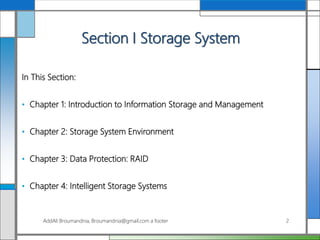
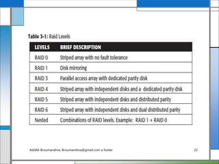
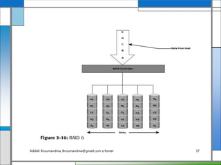
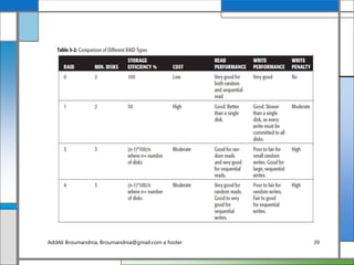
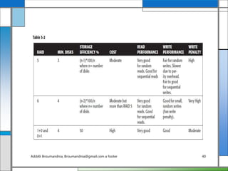
Information Storage and
Management
Storing, Managing, and Protecting Digital Information
AddAli Broumandnia, Broumandnia@gmail.com a footer 1
Section I Storage System
In This Section:
• Chapter 1: Introduction to Information Storage and Management
• Chapter 2: Storage System Environment
• Chapter 3: Data Protection: RAID
• Chapter 4: Intelligent Storage Systems
AddAli Broumandnia, Broumandnia@gmail.com a footer 2
Chapter 3
Data Protection: RAID
• 3.1 Implementation of RAID
• 3.2 RAID Array Components
• 3.3 RAID Levels
• 3.4 RAID Comparison
• 3.5 RAID Impact on Disk Performance
• 3.6 Hot Spares
• Summary
AddAli Broumandnia, Broumandnia@gmail.com a footer 3
Key Concepts:
• Hardware and Software RAID
• Striping, Mirroring, and Parity
• RAID Write Penalty
• Hot Spares
AddAli Broumandnia, Broumandnia@gmail.com a footer 4
This paper described the use of small-capacity,
inexpensive disk drives as an alternative to large-capacity
drives common on mainframe computers. The term
RAID has been redefined to refer to independent disks, to
reflect advances in the storage technology. RAID storage
has now grown from an academic concept to an industry
standard. This chapter details RAID technology, RAID
levels, and different types of RAID implementations and
their benefits.
AddAli Broumandnia, Broumandnia@gmail.com a footer 5
3.1 Implementation of RAID
• 3.1.1 Software RAID
• 3.1.2 Hardware RAID
AddAli Broumandnia, Broumandnia@gmail.com a footer 6
3.1.1 Software RAID
Software RAID uses host-based software to provide RAID
functions. It is implemented at the operating-system level
and does not use a dedicated hardware controller to
manage the RAID array. Software RAID implementations
offer cost and simplicity benefits when compared with
hardware RAID. However, they have the following
limitations:
AddAli Broumandnia, Broumandnia@gmail.com a footer 7
• Performance:
Software RAID affects overall system performance. This
is due to the additional CPU cycles required to perform
RAID calculations. The performance impact is more
pronounce for complex implementations of RAID, as
detailed later in this chapter.
AddAli Broumandnia, Broumandnia@gmail.com a footer 8
• Supported features:
Software RAID does not support all RAID levels.
• Operating system compatibility:
Software RAID is tied to the host operating system
hence upgrades to software RAID or to the operating
system should be validated for compatibility. This leads
to inflexibility in the data processing environment.
AddAli Broumandnia, Broumandnia@gmail.com a footer 9
3.1.2 Hardware RAID
The external RAID controller is an array-based hardware
RAID. It acts as an interface between the host and disks.
It presents storage volumes to the host, which manage
the drives using the supported protocol. Key functions of
RAID controllers are:
AddAli Broumandnia, Broumandnia@gmail.com a footer 10
• Management and control of disk aggregations
• Translation of I/O requests between logical disks and
physical disks
• Data regeneration in the event of disk failures
AddAli Broumandnia, Broumandnia@gmail.com a footer 11
3.2 RAID Array Components
A RAID array is an enclosure that contains a number of
HDDs and the supporting hardware and software to
implement RAID. HDDs inside a RAID array are usually
contained in smaller sub-enclosures. These sub-
enclosures, or physical arrays, hold a fixed number of
HDDs, and may also include other supporting hardware,
such as power supplies. A subset of disks within a RAID
array can be grouped to form logical associations called
logical arrays, also known as a RAID set or a RAID
group (see Figure 3-1).AddAli Broumandnia, Broumandnia@gmail.com a footer 12
AddAli Broumandnia, Broumandnia@gmail.com a footer 13
3.3 RAID Levels
RAID levels (see Table 3-1) are defined on the basis of
striping, mirroring, and parity techniques. These
techniques determine the data availability and
performance characteristics of an array. Some RAID
arrays use one technique, whereas others use a
combination of techniques. Application performance and
data availability requirements determine the RAID level
selection.
AddAli Broumandnia, Broumandnia@gmail.com a footer 14
3.3.1 Striping
A RAID set is a group of disks. Within each disk, a
predefined number of contiguously addressable disk
blocks are defined as strips. The set of aligned strips that
spans across all the disks within the RAID set is called a
stripe. Figure 3-2 shows physical and logical
representations of a striped RAID set.
AddAli Broumandnia, Broumandnia@gmail.com a footer 15
AddAli Broumandnia, Broumandnia@gmail.com a footer 16
3.3.2 Mirroring
Mirroring is a technique whereby data is stored on two
different HDDs, yielding two copies of data. In the event
of one HDD failure, the data is intact on the surviving
HDD (see Figure 3-3) and the controller continues to
service the host’s data requests from the surviving disk of
a mirrored pair.
AddAli Broumandnia, Broumandnia@gmail.com a footer 17
AddAli Broumandnia, Broumandnia@gmail.com a footer 18
3.3.3 Parity
Parity information can be stored on separate, dedicated
HDDs or distributed across all the drives in a RAID set.
Figure 3-4 shows a parity RAID. The first four disks,
labeled D, contain the data. The fifth disk, labeled P,
stores the parity information, which in this case is the
sum of the elements in each row. Now, if one of the Ds
fails, the missing value can be calculated by subtracting
the sum of the rest of the elements from the parity value.
AddAli Broumandnia, Broumandnia@gmail.com a footer 19
AddAli Broumandnia, Broumandnia@gmail.com a footer 20
In Figure 3-4, the computation of parity is represented as
a simple arithmetic operation on the data. However,
parity calculation is a bitwise XOR operation. Calculation
of parity is a function of the RAID controller.
Parity information is generated from data on the data
disk. Therefore, parity is recalculated every time there is
a change in data. This recalculation is time-consuming
and affects the performance of the RAID controller.
AddAli Broumandnia, Broumandnia@gmail.com a footer 21
AddAli Broumandnia, Broumandnia@gmail.com a footer 22
3.3.4 RAID 0
In a RAID 0 configuration, data is striped across the
HDDs in a RAID set. It utilizes the full storage capacity
by distributing strips of data over multiple HDDs in a
RAID set. To read data, all the strips are put back
together by the controller. The stripe size is specified at a
host level for software RAID and is vendor specific for
hardware RAID. Figure 3-5 shows RAID 0 on a storage
array in which data is striped across 5 disks.
AddAli Broumandnia, Broumandnia@gmail.com a footer 23
AddAli Broumandnia, Broumandnia@gmail.com a footer 24
3.3.5 RAID 1
In a RAID 1 configuration, data is mirrored to improve
fault tolerance (see Figure 3-6). A RAID 1 group consists
of at least two HDDs. As explained in mirroring, every
write is written to both disks, which is transparent to the
host in a hardware RAID implementation.
AddAli Broumandnia, Broumandnia@gmail.com a footer 25
AddAli Broumandnia, Broumandnia@gmail.com a footer 26
3.3.6 Nested RAID
Most data centers require data redundancy and
performance from their RAID arrays. RAID 0+1 and
RAID 1+0 combine the performance benefits of RAID 0
with the redundancy benefits of RAID 1. They use
striping and mirroring techniques and combine their
benefits. These types of RAID require an even number of
disks, the minimum being four (see Figure 3-7).
Some applications that benefit from RAID 1+0 include
the following:AddAli Broumandnia, Broumandnia@gmail.com a footer 27
High transaction rate Online Transaction Processing
(OLTP)
Large messaging installations
Database applications that require high I/O rate,
random access, and high availability
AddAli Broumandnia, Broumandnia@gmail.com a footer 28
3.3.7 RAID 3
RAID 3 stripes data for high performance and uses parity
for improved fault tolerance. Parity information is stored
on a dedicated drive so that data can be reconstructed if a
drive fails. For example, of five disks, four are used for
data and one is used for parity. Therefore, the total disk
space required is 1.25 times the size of the data disks.
RAID 3 always reads and writes complete stripes of data
across all disks, as the drives operate in parallel. There are
no partial writes that update one out of many strips in a
stripe. Figure 3-8 illustrates the RAID 3 implementation.
AddAli Broumandnia, Broumandnia@gmail.com a footer 29
AddAli Broumandnia, Broumandnia@gmail.com a footer 30
AddAli Broumandnia, Broumandnia@gmail.com a footer 31
RAID 3 provides good bandwidth for the transfer of
large volumes of data. RAID 3 is used in applications
that involve large sequential data access, such as video
streaming.
AddAli Broumandnia, Broumandnia@gmail.com a footer 32
3.3.8 RAID 4
Similar to RAID 3, RAID 4 stripes data for high
performance and uses parity for improved fault tolerance
(refer to Figure 3-8). Data is striped across all disks
except the parity disk in the array. Parity information is
stored on a dedicated disk so that the data can be rebuilt
if a drive fails. Striping is done at the block level.
AddAli Broumandnia, Broumandnia@gmail.com a footer 33
3.3.9 RAID 5
RAID 5 is a very versatile RAID implementation. It is
similar to RAID 4 because it uses striping and the drives
(strips) are independently accessible. The difference
between RAID 4 and RAID 5 is the parity location. In
RAID 4, parity is written to a dedicated drive, creating a
write bottleneck for the parity disk. In RAID 5, parity is
distributed across all disks. The distribution of parity in
RAID 5 overcomes the write bottleneck. Figure 3-9
illustrates the RAID 5 implementation.
AddAli Broumandnia, Broumandnia@gmail.com a footer 34
AddAli Broumandnia, Broumandnia@gmail.com a footer 35
3.3.10 RAID 6
RAID 6 works the same way as RAID 5 except that
RAID 6 includes a second parity element to enable
survival in the event of the failure of two disks in a
RAID group (see Figure 3-10). Therefore, a RAID 6
implementation requires at least four disks. RAID 6
distributes the parity across all the disks. The write
penalty in RAID 6 is more than that in RAID 5;
therefore, RAID 5 writes perform better than RAID 6.
The rebuild operation in RAID 6 may take longer than
that in RAID 5 due to the presence of two parity sets.
AddAli Broumandnia, Broumandnia@gmail.com a footer 36
AddAli Broumandnia, Broumandnia@gmail.com a footer 37
3.4 RAID Comparison
Table 3-2 compares the different types of RAID.
AddAli Broumandnia, Broumandnia@gmail.com a footer 38
AddAli Broumandnia, Broumandnia@gmail.com a footer 39
AddAli Broumandnia, Broumandnia@gmail.com a footer 40
3.5 RAID Impact on Disk Performance
In a RAID 1 implementation, every write operation must
be performed on two disks configured as a mirrored pair
while in a RAID 5 implementation, a write operation
may manifest as four I/O operations. When performing
small I/Os to a disk configured with RAID 5, the
controller has to read, calculate, and write a parity
segment for every data write operation.
AddAli Broumandnia, Broumandnia@gmail.com a footer 41
Figure 3-11 illustrates a single write operation on RAID
5 that contains a group of five disks. Four of these disks
are used for data and one is used for parity.
AddAli Broumandnia, Broumandnia@gmail.com a footer 42
AddAli Broumandnia, Broumandnia@gmail.com a footer 43
3.5.1 Application IOPS and RAID
Configurations
When deciding the number of disks required for an
application, it is important to consider the impact of
RAID based on IOPS generated by the application. The
total disk load should be computed by considering the
type of RAID configuration and the ratio of read
compared to write from the host.
AddAli Broumandnia, Broumandnia@gmail.com a footer 44
The computed disk load determines the number of disks
required for the application. If in this example an HDD
with a specification of a maximum 180 IOPS for the
application needs to be used, the number of disks
required to meet the workload for the RAID
configuration would be as follows:
AddAli Broumandnia, Broumandnia@gmail.com a footer 45
RAID 5: 11,440 / 180 = 64 disks
RAID 1: 7,280 / 180 = 42 disks (approximated to the
nearest even number)
AddAli Broumandnia, Broumandnia@gmail.com a footer 46
3.6 Hot Spares
A hot spare refers to a spare HDD in a RAID array that
temporarily replaces a failed HDD of a RAID set. A hot
spare takes the identity of the failed HDD in the array.
One of the following methods of data recovery is
performed depending on the RAID implementation:
AddAli Broumandnia, Broumandnia@gmail.com a footer 47
If parity RAID is used, then the data is rebuilt onto the
hot spare from the parity and the data on the surviving
HDDs in the RAID set.
If mirroring is used, then the data from the surviving
mirror is used to copy the data.
AddAli Broumandnia, Broumandnia@gmail.com a footer 48
When the failed HDD is replaced with a new HDD, one
of the following takes place:
The hot spare replaces the new HDD permanently. This
means that it is no longer a hot spare, and a new hot
spare must be configured on the array.
When a new HDD is added to the system, data from
the hot spare is copied to it. The hot spare returns to its
idle state, ready to replace the next failed drive.
AddAli Broumandnia, Broumandnia@gmail.com a footer 49
Summary
Individual disks are prone to failures and pose the threat
of data unavailability for applications. RAID addresses
data availability requirements by using mirroring and
parity techniques. RAID implementations with striping
enhance I/O performance by spreading data across
multiple HDDs in addition to redundancy benefits.
AddAli Broumandnia, Broumandnia@gmail.com a footer 50
This chapter explained the fundamental constructs of striping,
mirroring, and parity, which form the basis for various RAID
levels. Implementation of RAID levels depends on application
requirements for performance and data protection. RAID is
the cornerstone technology for several advancements in
storage. The next generation of storage systems are intelligent
storage systems that implement RAID along with a
specialized operating environment that offers high
performance and availability. Intelligent storage systems are
detailed in the next chapter.
AddAli Broumandnia, Broumandnia@gmail.com a footer 51

Chapter 3

  • 1.
    Information Storage and Management Storing,Managing, and Protecting Digital Information AddAli Broumandnia, Broumandnia@gmail.com a footer 1
  • 2.
    Section I StorageSystem In This Section: • Chapter 1: Introduction to Information Storage and Management • Chapter 2: Storage System Environment • Chapter 3: Data Protection: RAID • Chapter 4: Intelligent Storage Systems AddAli Broumandnia, Broumandnia@gmail.com a footer 2
  • 3.
    Chapter 3 Data Protection:RAID • 3.1 Implementation of RAID • 3.2 RAID Array Components • 3.3 RAID Levels • 3.4 RAID Comparison • 3.5 RAID Impact on Disk Performance • 3.6 Hot Spares • Summary AddAli Broumandnia, Broumandnia@gmail.com a footer 3
  • 4.
    Key Concepts: • Hardwareand Software RAID • Striping, Mirroring, and Parity • RAID Write Penalty • Hot Spares AddAli Broumandnia, Broumandnia@gmail.com a footer 4
  • 5.
    This paper describedthe use of small-capacity, inexpensive disk drives as an alternative to large-capacity drives common on mainframe computers. The term RAID has been redefined to refer to independent disks, to reflect advances in the storage technology. RAID storage has now grown from an academic concept to an industry standard. This chapter details RAID technology, RAID levels, and different types of RAID implementations and their benefits. AddAli Broumandnia, Broumandnia@gmail.com a footer 5
  • 6.
    3.1 Implementation ofRAID • 3.1.1 Software RAID • 3.1.2 Hardware RAID AddAli Broumandnia, Broumandnia@gmail.com a footer 6
  • 7.
    3.1.1 Software RAID SoftwareRAID uses host-based software to provide RAID functions. It is implemented at the operating-system level and does not use a dedicated hardware controller to manage the RAID array. Software RAID implementations offer cost and simplicity benefits when compared with hardware RAID. However, they have the following limitations: AddAli Broumandnia, Broumandnia@gmail.com a footer 7
  • 8.
    • Performance: Software RAIDaffects overall system performance. This is due to the additional CPU cycles required to perform RAID calculations. The performance impact is more pronounce for complex implementations of RAID, as detailed later in this chapter. AddAli Broumandnia, Broumandnia@gmail.com a footer 8
  • 9.
    • Supported features: SoftwareRAID does not support all RAID levels. • Operating system compatibility: Software RAID is tied to the host operating system hence upgrades to software RAID or to the operating system should be validated for compatibility. This leads to inflexibility in the data processing environment. AddAli Broumandnia, Broumandnia@gmail.com a footer 9
  • 10.
    3.1.2 Hardware RAID Theexternal RAID controller is an array-based hardware RAID. It acts as an interface between the host and disks. It presents storage volumes to the host, which manage the drives using the supported protocol. Key functions of RAID controllers are: AddAli Broumandnia, Broumandnia@gmail.com a footer 10
  • 11.
    • Management andcontrol of disk aggregations • Translation of I/O requests between logical disks and physical disks • Data regeneration in the event of disk failures AddAli Broumandnia, Broumandnia@gmail.com a footer 11
  • 12.
    3.2 RAID ArrayComponents A RAID array is an enclosure that contains a number of HDDs and the supporting hardware and software to implement RAID. HDDs inside a RAID array are usually contained in smaller sub-enclosures. These sub- enclosures, or physical arrays, hold a fixed number of HDDs, and may also include other supporting hardware, such as power supplies. A subset of disks within a RAID array can be grouped to form logical associations called logical arrays, also known as a RAID set or a RAID group (see Figure 3-1).AddAli Broumandnia, Broumandnia@gmail.com a footer 12
  • 13.
  • 14.
    3.3 RAID Levels RAIDlevels (see Table 3-1) are defined on the basis of striping, mirroring, and parity techniques. These techniques determine the data availability and performance characteristics of an array. Some RAID arrays use one technique, whereas others use a combination of techniques. Application performance and data availability requirements determine the RAID level selection. AddAli Broumandnia, Broumandnia@gmail.com a footer 14
  • 15.
    3.3.1 Striping A RAIDset is a group of disks. Within each disk, a predefined number of contiguously addressable disk blocks are defined as strips. The set of aligned strips that spans across all the disks within the RAID set is called a stripe. Figure 3-2 shows physical and logical representations of a striped RAID set. AddAli Broumandnia, Broumandnia@gmail.com a footer 15
  • 16.
  • 17.
    3.3.2 Mirroring Mirroring isa technique whereby data is stored on two different HDDs, yielding two copies of data. In the event of one HDD failure, the data is intact on the surviving HDD (see Figure 3-3) and the controller continues to service the host’s data requests from the surviving disk of a mirrored pair. AddAli Broumandnia, Broumandnia@gmail.com a footer 17
  • 18.
  • 19.
    3.3.3 Parity Parity informationcan be stored on separate, dedicated HDDs or distributed across all the drives in a RAID set. Figure 3-4 shows a parity RAID. The first four disks, labeled D, contain the data. The fifth disk, labeled P, stores the parity information, which in this case is the sum of the elements in each row. Now, if one of the Ds fails, the missing value can be calculated by subtracting the sum of the rest of the elements from the parity value. AddAli Broumandnia, Broumandnia@gmail.com a footer 19
  • 20.
  • 21.
    In Figure 3-4,the computation of parity is represented as a simple arithmetic operation on the data. However, parity calculation is a bitwise XOR operation. Calculation of parity is a function of the RAID controller. Parity information is generated from data on the data disk. Therefore, parity is recalculated every time there is a change in data. This recalculation is time-consuming and affects the performance of the RAID controller. AddAli Broumandnia, Broumandnia@gmail.com a footer 21
  • 22.
  • 23.
    3.3.4 RAID 0 Ina RAID 0 configuration, data is striped across the HDDs in a RAID set. It utilizes the full storage capacity by distributing strips of data over multiple HDDs in a RAID set. To read data, all the strips are put back together by the controller. The stripe size is specified at a host level for software RAID and is vendor specific for hardware RAID. Figure 3-5 shows RAID 0 on a storage array in which data is striped across 5 disks. AddAli Broumandnia, Broumandnia@gmail.com a footer 23
  • 24.
  • 25.
    3.3.5 RAID 1 Ina RAID 1 configuration, data is mirrored to improve fault tolerance (see Figure 3-6). A RAID 1 group consists of at least two HDDs. As explained in mirroring, every write is written to both disks, which is transparent to the host in a hardware RAID implementation. AddAli Broumandnia, Broumandnia@gmail.com a footer 25
  • 26.
  • 27.
    3.3.6 Nested RAID Mostdata centers require data redundancy and performance from their RAID arrays. RAID 0+1 and RAID 1+0 combine the performance benefits of RAID 0 with the redundancy benefits of RAID 1. They use striping and mirroring techniques and combine their benefits. These types of RAID require an even number of disks, the minimum being four (see Figure 3-7). Some applications that benefit from RAID 1+0 include the following:AddAli Broumandnia, Broumandnia@gmail.com a footer 27
  • 28.
    High transaction rateOnline Transaction Processing (OLTP) Large messaging installations Database applications that require high I/O rate, random access, and high availability AddAli Broumandnia, Broumandnia@gmail.com a footer 28
  • 29.
    3.3.7 RAID 3 RAID3 stripes data for high performance and uses parity for improved fault tolerance. Parity information is stored on a dedicated drive so that data can be reconstructed if a drive fails. For example, of five disks, four are used for data and one is used for parity. Therefore, the total disk space required is 1.25 times the size of the data disks. RAID 3 always reads and writes complete stripes of data across all disks, as the drives operate in parallel. There are no partial writes that update one out of many strips in a stripe. Figure 3-8 illustrates the RAID 3 implementation. AddAli Broumandnia, Broumandnia@gmail.com a footer 29
  • 30.
  • 31.
  • 32.
    RAID 3 providesgood bandwidth for the transfer of large volumes of data. RAID 3 is used in applications that involve large sequential data access, such as video streaming. AddAli Broumandnia, Broumandnia@gmail.com a footer 32
  • 33.
    3.3.8 RAID 4 Similarto RAID 3, RAID 4 stripes data for high performance and uses parity for improved fault tolerance (refer to Figure 3-8). Data is striped across all disks except the parity disk in the array. Parity information is stored on a dedicated disk so that the data can be rebuilt if a drive fails. Striping is done at the block level. AddAli Broumandnia, Broumandnia@gmail.com a footer 33
  • 34.
    3.3.9 RAID 5 RAID5 is a very versatile RAID implementation. It is similar to RAID 4 because it uses striping and the drives (strips) are independently accessible. The difference between RAID 4 and RAID 5 is the parity location. In RAID 4, parity is written to a dedicated drive, creating a write bottleneck for the parity disk. In RAID 5, parity is distributed across all disks. The distribution of parity in RAID 5 overcomes the write bottleneck. Figure 3-9 illustrates the RAID 5 implementation. AddAli Broumandnia, Broumandnia@gmail.com a footer 34
  • 35.
  • 36.
    3.3.10 RAID 6 RAID6 works the same way as RAID 5 except that RAID 6 includes a second parity element to enable survival in the event of the failure of two disks in a RAID group (see Figure 3-10). Therefore, a RAID 6 implementation requires at least four disks. RAID 6 distributes the parity across all the disks. The write penalty in RAID 6 is more than that in RAID 5; therefore, RAID 5 writes perform better than RAID 6. The rebuild operation in RAID 6 may take longer than that in RAID 5 due to the presence of two parity sets. AddAli Broumandnia, Broumandnia@gmail.com a footer 36
  • 37.
  • 38.
    3.4 RAID Comparison Table3-2 compares the different types of RAID. AddAli Broumandnia, Broumandnia@gmail.com a footer 38
  • 39.
  • 40.
  • 41.
    3.5 RAID Impacton Disk Performance In a RAID 1 implementation, every write operation must be performed on two disks configured as a mirrored pair while in a RAID 5 implementation, a write operation may manifest as four I/O operations. When performing small I/Os to a disk configured with RAID 5, the controller has to read, calculate, and write a parity segment for every data write operation. AddAli Broumandnia, Broumandnia@gmail.com a footer 41
  • 42.
    Figure 3-11 illustratesa single write operation on RAID 5 that contains a group of five disks. Four of these disks are used for data and one is used for parity. AddAli Broumandnia, Broumandnia@gmail.com a footer 42
  • 43.
  • 44.
    3.5.1 Application IOPSand RAID Configurations When deciding the number of disks required for an application, it is important to consider the impact of RAID based on IOPS generated by the application. The total disk load should be computed by considering the type of RAID configuration and the ratio of read compared to write from the host. AddAli Broumandnia, Broumandnia@gmail.com a footer 44
  • 45.
    The computed diskload determines the number of disks required for the application. If in this example an HDD with a specification of a maximum 180 IOPS for the application needs to be used, the number of disks required to meet the workload for the RAID configuration would be as follows: AddAli Broumandnia, Broumandnia@gmail.com a footer 45
  • 46.
    RAID 5: 11,440/ 180 = 64 disks RAID 1: 7,280 / 180 = 42 disks (approximated to the nearest even number) AddAli Broumandnia, Broumandnia@gmail.com a footer 46
  • 47.
    3.6 Hot Spares Ahot spare refers to a spare HDD in a RAID array that temporarily replaces a failed HDD of a RAID set. A hot spare takes the identity of the failed HDD in the array. One of the following methods of data recovery is performed depending on the RAID implementation: AddAli Broumandnia, Broumandnia@gmail.com a footer 47
  • 48.
    If parity RAIDis used, then the data is rebuilt onto the hot spare from the parity and the data on the surviving HDDs in the RAID set. If mirroring is used, then the data from the surviving mirror is used to copy the data. AddAli Broumandnia, Broumandnia@gmail.com a footer 48
  • 49.
    When the failedHDD is replaced with a new HDD, one of the following takes place: The hot spare replaces the new HDD permanently. This means that it is no longer a hot spare, and a new hot spare must be configured on the array. When a new HDD is added to the system, data from the hot spare is copied to it. The hot spare returns to its idle state, ready to replace the next failed drive. AddAli Broumandnia, Broumandnia@gmail.com a footer 49
  • 50.
    Summary Individual disks areprone to failures and pose the threat of data unavailability for applications. RAID addresses data availability requirements by using mirroring and parity techniques. RAID implementations with striping enhance I/O performance by spreading data across multiple HDDs in addition to redundancy benefits. AddAli Broumandnia, Broumandnia@gmail.com a footer 50
  • 51.
    This chapter explainedthe fundamental constructs of striping, mirroring, and parity, which form the basis for various RAID levels. Implementation of RAID levels depends on application requirements for performance and data protection. RAID is the cornerstone technology for several advancements in storage. The next generation of storage systems are intelligent storage systems that implement RAID along with a specialized operating environment that offers high performance and availability. Intelligent storage systems are detailed in the next chapter. AddAli Broumandnia, Broumandnia@gmail.com a footer 51