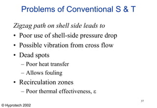
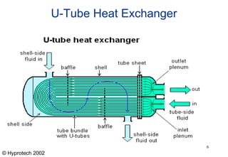
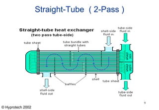
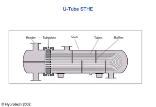
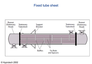
Shell and tube heat exchangers consist of tubes housed inside a large shell vessel. Fluids of different temperatures are circulated through the tubes and shell without mixing. Common types include U-tube, straight tube single pass, and straight tube double pass configurations. Heat is transferred between the fluids through the tubes and baffles direct the shell-side fluid flow across the tubes. Shell and tube heat exchangers are widely used due to their design flexibility, reliability, and ability to operate at a wide range of pressures and temperatures.


![© Hyprotech 2002
Heat Exchanger Calculations
• Heat transfer rate
QTS = mCpDT
QSS = mDH + mCpDT
• Overall heat transfer coefficient
QSS = Uo(Ao*DTLM)
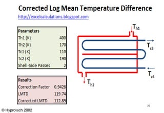
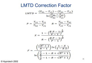
Log mean temperature
DTLM = ((Thi-Tco) – (Tho – Tci)) / ln[(Thi – Tco) – (Tho – Tci)]
29](https://image.slidesharecdn.com/pptonheatexchanger-231107193653-d190e7e7/85/PPT-on-Heat-Exchanger-19-ppt-29-320.jpg)