Download to read offline


![www.ipec.info
Thermal Design
The thermal design of a shell and tube exchanger is an iterative process which is normally carried out using
computer programs from organizations such as the Heat transfer and Fluid Flow Service (HTFS) or Heat
Transfer Research Incorporated (HTRI). However, it is important that the engineer understands the logic
behind the calculation. In order to calculate the heat transfer coefficients and pressure drops, initial decisions
must be made on the sides the fluids are allocated, the front and rear header type, shell type, baffle type, tube
diameter and tube layout. The tube length, shell diameter, baffle pitch and number of tube passes are also
selected and these are normally the main items that are altered during each iteration in order to maximize the
overall heat transfer within specified allowable pressure drops.
The main steps in the calculation are given below together with calculation methods in the open literature:
1. Calculate the shellside flow distribution [Use Bell-Delaware Method, see Hewitt, Shires, and Bott
(1994)].
2. Calculate the shellside heat transfer coefficient (Use Bell- Delaware Method)
3. Calculate tubeside heat transfer coefficient (see, for example, Tubes: Single Phase Heat Transfer In).
4. Calculate tubeside pressure drop (see, for example, Pressure Drop, Single Phase).
5. Calculate wall resistance and overall heat transfer coefficient (see Overall Heat Transfer Coefficient and
Fouling).
6. Calculate mean temperature difference (see Mean Temperature Difference).
7. Calculate area required.
8. Compare area required with area of assumed geometry and allowed tubeside and shellside pressure drop
with calculated values.](https://image.slidesharecdn.com/heatexchangers-ipec-150519082653-lva1-app6891/85/Heat-exchangers-ipec-info-22-320.jpg)
![www.ipec.info
9. Adjust assumed geometry and repeat calculations until Area required is achieved within the allowable
pressure drops.
Books by E. A. D. Saunders [Saunders (1988)] and G. F. Hewitt, G. L. Shires, and T. R. Bott [Hewitt et al.
(1994)] provides a good overview of tubular thermal design methods and example calculations.
Mechanical Design
The mechanical design of a shell and tube heat exchanger provides information on items such as shell thickness,
flange thickness, etc. These are calculated using a pressure vessel design code such as the Boiler and Pressure
Vessel code from ASME (American Society of Mechanical Engineers) and the British Master Pressure Vessel
Standard, BS 5500. ASME is the most commonly used code for heat exchangers and is in 11 sections. Section
VIII (Confined Pressure Vessels) of the code is the most applicable to heat exchangers but Sections II Materials
and Section V Non Destructive Testing are also relevant.
Both ASME and BS5500 are widely used and accepted throughout the world but some countries insist that their
own national codes are used. In order to try and simplify this the International Standards Organization is now
attempting to develop a new internationally recognized code but it is likely to be a some time before this is
accepted.
References:
1. TEMA Seventh Edition. (1988) Tubular Exchanger Manufacturers Association.
2. Saunders, E. A. D. (1988) Heat Exchangers Selection, Design and Construction, Longman Scientific and
Technical.
3. Hewitt, G. F, Shires, G. L., and Bott, T. R. (1994) Process Heat Transfer, CRC Press.
4. Boiler and Pressure Vessel code, ASME (American Society of Mechanical Engineers).](https://image.slidesharecdn.com/heatexchangers-ipec-150519082653-lva1-app6891/85/Heat-exchangers-ipec-info-23-320.jpg)

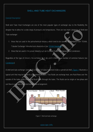
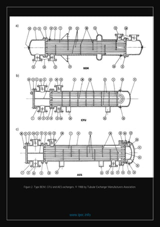
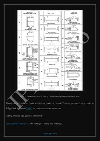
This document provides an overview of shell and tube heat exchangers. It describes the basic components and design types, including fixed tubesheet, U-tube, and floating head exchangers. Various header, shell, and baffle configurations are defined according to TEMA nomenclature standards. Geometric options like tube layout, baffle type, and heat transfer enhancement devices are also discussed. Selection criteria for shell and tube exchangers consider factors like accessibility, thermal expansion capabilities, pressure handling, and cost.


