Download to read offline

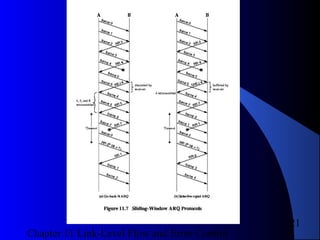
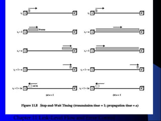
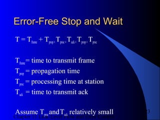
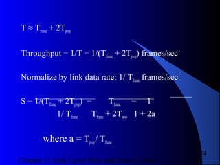
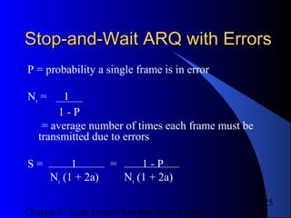
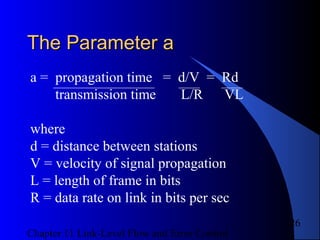
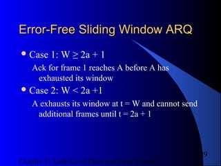
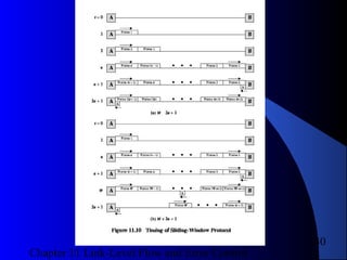
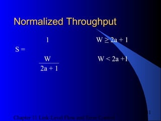
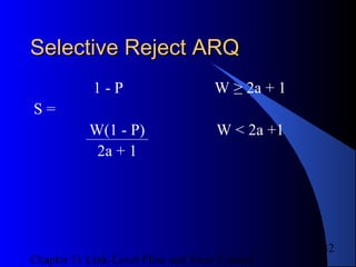

This document summarizes flow and error control mechanisms at the link layer. It discusses stop-and-wait, go-back-N, and selective reject protocols for automatic repeat request (ARQ). These protocols use sliding windows, acknowledgments, and retransmissions to provide reliable data transfer over unreliable links. Performance analysis is presented showing how throughput is affected by window size, propagation delay, and error rates. High-level data link control (HDLC) is also introduced as an important link layer protocol.