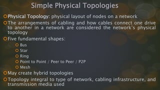
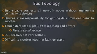
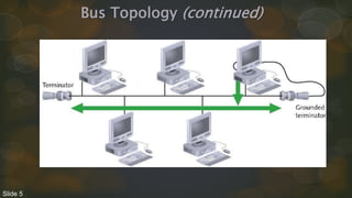
Network Topologies
Chapter: 03
Computer Networks
By Prof: M. Naeem Akhtar
Simple Physical Topologies
Physical Topology: physical layout of nodes on a network
The arrangements of cabling and how cables connect one drive
to another in a network are considered the network’s physical
topology
Five fundamental shapes:
 Bus
 Star
 Ring
 Point to Point / Peer to Peer / P2P
 Mesh
May create hybrid topologies
Topology integral to type of network, cabling infrastructure, and
transmission media used
Bus Topology
Single cable connects all network nodes without intervening
connectivity devices
Devices share responsibility for getting data from one point to
another
Terminators stop signals after reaching end of wire
 Prevent signal bounce
Inexpensive, not very scalable
Difficult to troubleshoot, not fault-tolerant
Slide 4
Bus Topology (continued)
Slide 5
Advantages of Bus Topology
Works well for small networks
Relatively inexpensive to implement
Easy to add to it – strength of bus’s topology
Weaknesses of strength:
There’s limit of 30 computers per cable segment
Maximum total length of cabling is 185 meters
Both ends of the bus must be terminated
Any break in the bus brings down the entire network
Adding or removing a machine brings down the entire network temporarily
Technologies of this topology limited to 10 Mbps half duplex communication
because of using coaxial cabling
Slide 6
How Data Travels in a Physical Bus
Information travels across the media as a series of signals as
electrical pulses
These signals continue travelling along the cable through devices
until they weaken enough to detect signal propagation
To avoid the reflection or bouncing back, you should install
terminators at the end of the medium.
Slide 7
Disadvantages of Bus Topology
Management costs can be high
Potential for congestion with network traffic
Limitation of 30 computers per cable segment
 30 computers can be daisy chain together
Limitation of total cabling length is 185 meters
Max bandwidth 10 Mbps with coaxial cable
Max bandwidth 100 Mbps with twisted pair cables 26
Slide 8
Physical Star Topologies
Slide 9
Star Topologies
Star Topology uses a central device such as a hub or switch, to
interconnect computers in a LAN
Every node on the network is connected through a central device
Each computer has a single length of cable going from its NIC to the
central device
Slide 10
Star Topology (continued)
Any single cable connects only two devices
 Cabling problems affect two nodes at most
Requires more cabling than ring or bus networks
 More fault-tolerant
Easily moved, isolated, or interconnected with other networks
 Scalable
Supports max of 1024 addressable nodes on logical network
Slide 11
Physical Start Topology
Advantages of Star Topology
Much faster than bus topology
Centralized monitoring and management of network traffic is
possible – Easy to manage
Good option for modern networks
Low startup costs
Offers opportunities for expansion
Network upgrades are easier
Most popular topology in use; wide variety of equipment available
Slide 12
Physical Star Topology
How Data Travels in a Physical Star
Data travelling in the network depends on the type of central devices
Data transmission starts from the computer along the medium until
it reaches the central device .
Transmission paths differs through Hubs, switches etc.
Transmission paths also differs due to logical topology such as
Ethernet and Token ring.
Slide 13
Physical Star Topology
Extended Star Topology
Star topology is a good option for modern networks as it offers
opportunities for expansion of networks instead of computers
A central device, Hub/Switch, sits at the middle forming additional
stars referred to hierarchical star
This topology is most effective when the center of the star is running
at a much faster (1000 Mbps) than other devices (100 Mbps).
Slide 14
Physical Star Topology
Disadvantages of Star Topology
Hub is a single point of failure
Requires more cable than the bus
Contrary to daisy chain
Slide 15
Physical Ring Topology
• In Ring topology devices are attached (like bus topology) in daisy
chain.
• But instead terminating each end, the cabling is brought around the
last device back to the first device to form a ring.
Slide 16
Physical Ring Topology
Also has reliability issues as data had to transmit from one station to
the next – as in bus data is forward to all directions and terminated at
both ends
A ring doesn't have any beginning or end.
Each station produce data and pass to the next station until it reaches
the destination
Ring topology used FDDI technology (Fiber Distributed data Interface)
to expand LANs and as well to avoid the dual ring
However FDDI technology is costly.
Slide 17
Physical Ring Topology
Advantages:
 Easier to manage; easier to locate a defective node or cable problem
 Well-suited for transmitting signals over long distances on a LAN
 Handles high-volume network traffic
 Enables reliable communication
Slide 18
Physical Ring Topology
Disadvantages
 Expensive
 Requires more cable and network equipment at the start
 Not used as widely as bus topology
Fewer equipment options
Fewer options for expansion to high-speed communication
Slide 19
Point to Point Topology
In point to point topology there is a direct link between two
computers/devices
Often used in WAN – as business's network has a dedicated link to
a communication provider.
Data travels in dedicated link and did not share its bandwidth –
advantage
This topology tends to expensive when used as a WAN link to a
distant branch office – disadvantage
Slide 20
Physical Mesh Topology
A Mesh topology connects each device to every other devices in a
network.
In mesh topology multiple point to point connections for the
purpose of redundancy and fault tolerance
If each computer or switch is connected with each other then is
called “mesh topology” otherwise called “partial mesh”.
Provides fast and collision free communication.
Difficult to install and manage a lot of cables
Initial cost is mush high – expensive topology
Slide 21
Logical Topologies
Logical topology: how data is transmitted between nodes
May not match physical topology
Bus logical topology: signals travel from one network device to
all other devices on network
Required by bus, star, star-wired physical topologies
Ring logical topology: signals follow circular path between
sender and receiver
Required by ring, star-wired ring topologies
Slide 22
Baseband and Broadband Signals
Baseband Signals
• A transmission method which sends digital signal of each bit
represented by a pulse of electricity (on copper media) or light pulse
(on fiber-optic).
• These signals are sent at a single fixed frequency, using the
medium’s entire bandwidth.
• As these signals occupies the entire bandwidth so no other frames
can be sent along with it.
Slide 23
Baseband and Broadband Signals
Broadband Signals:
• Broadband systems use analog techniques to encode binary 1s and
0s across a continuous range of values.
• These signals move across the medium in the form of continuous
electromagnetic or optical waves rather than discrete pulses.
• On broadband systems signals flow at a particular frequency and
each frequency represents a channel of data
• different frequencies represents different channels.
Slide 24
Token Ring Networks
(developed by IBM in 1980s)
 This technology provides albeit slow by today’s standards, transport
of data
 Based on IEEE 802.5 standard, token ring networks are cabled in a
physical star topology but function as a logical ring
 Token ring originally operates at 4 Mbps but now increased to 16
Mbps and later to 100 Mbps in 2001.
 Most token ring networks used Cat-4 or higher UTP.
Slide 25
Token Ring Networks
Token Ring Media Access
 Token Ring uses the token passing media access method, in which
a special frame called the “token” passes from one computer to the
next
 Only the computer having the token can send data
 One computer can hold the token for a specific amount of time, if it
has not to sent data it passes the token to the next computer.
 No collision in token ring because of token and there’s possibility
of collisions in CSMA/CD as every computer is sensing the media.
Slide 26
Token Ring Networks
Token Ring Media Access Disadvantages
1.
 Computer have to wait for the token.
 In case of large amount of data after first transmission there
might be wait time for second transmission because a circuit
should have to complete.
2.
 Complicated process of creating and passing tokens
 More expensive equipment than what’s used in CSMA/CD.
Slide 27
Thanks for giving your attention

Chapter 1 - Network Topologies.pptx

  • 2.
    Network Topologies Chapter: 03 ComputerNetworks By Prof: M. Naeem Akhtar
  • 3.
    Simple Physical Topologies PhysicalTopology: physical layout of nodes on a network The arrangements of cabling and how cables connect one drive to another in a network are considered the network’s physical topology Five fundamental shapes:  Bus  Star  Ring  Point to Point / Peer to Peer / P2P  Mesh May create hybrid topologies Topology integral to type of network, cabling infrastructure, and transmission media used
  • 4.
    Bus Topology Single cableconnects all network nodes without intervening connectivity devices Devices share responsibility for getting data from one point to another Terminators stop signals after reaching end of wire  Prevent signal bounce Inexpensive, not very scalable Difficult to troubleshoot, not fault-tolerant Slide 4
  • 5.
  • 6.
    Advantages of BusTopology Works well for small networks Relatively inexpensive to implement Easy to add to it – strength of bus’s topology Weaknesses of strength: There’s limit of 30 computers per cable segment Maximum total length of cabling is 185 meters Both ends of the bus must be terminated Any break in the bus brings down the entire network Adding or removing a machine brings down the entire network temporarily Technologies of this topology limited to 10 Mbps half duplex communication because of using coaxial cabling Slide 6
  • 7.
    How Data Travelsin a Physical Bus Information travels across the media as a series of signals as electrical pulses These signals continue travelling along the cable through devices until they weaken enough to detect signal propagation To avoid the reflection or bouncing back, you should install terminators at the end of the medium. Slide 7
  • 8.
    Disadvantages of BusTopology Management costs can be high Potential for congestion with network traffic Limitation of 30 computers per cable segment  30 computers can be daisy chain together Limitation of total cabling length is 185 meters Max bandwidth 10 Mbps with coaxial cable Max bandwidth 100 Mbps with twisted pair cables 26 Slide 8
  • 9.
  • 10.
    Star Topologies Star Topologyuses a central device such as a hub or switch, to interconnect computers in a LAN Every node on the network is connected through a central device Each computer has a single length of cable going from its NIC to the central device Slide 10
  • 11.
    Star Topology (continued) Anysingle cable connects only two devices  Cabling problems affect two nodes at most Requires more cabling than ring or bus networks  More fault-tolerant Easily moved, isolated, or interconnected with other networks  Scalable Supports max of 1024 addressable nodes on logical network Slide 11
  • 12.
    Physical Start Topology Advantagesof Star Topology Much faster than bus topology Centralized monitoring and management of network traffic is possible – Easy to manage Good option for modern networks Low startup costs Offers opportunities for expansion Network upgrades are easier Most popular topology in use; wide variety of equipment available Slide 12
  • 13.
    Physical Star Topology HowData Travels in a Physical Star Data travelling in the network depends on the type of central devices Data transmission starts from the computer along the medium until it reaches the central device . Transmission paths differs through Hubs, switches etc. Transmission paths also differs due to logical topology such as Ethernet and Token ring. Slide 13
  • 14.
    Physical Star Topology ExtendedStar Topology Star topology is a good option for modern networks as it offers opportunities for expansion of networks instead of computers A central device, Hub/Switch, sits at the middle forming additional stars referred to hierarchical star This topology is most effective when the center of the star is running at a much faster (1000 Mbps) than other devices (100 Mbps). Slide 14
  • 15.
    Physical Star Topology Disadvantagesof Star Topology Hub is a single point of failure Requires more cable than the bus Contrary to daisy chain Slide 15
  • 16.
    Physical Ring Topology •In Ring topology devices are attached (like bus topology) in daisy chain. • But instead terminating each end, the cabling is brought around the last device back to the first device to form a ring. Slide 16
  • 17.
    Physical Ring Topology Alsohas reliability issues as data had to transmit from one station to the next – as in bus data is forward to all directions and terminated at both ends A ring doesn't have any beginning or end. Each station produce data and pass to the next station until it reaches the destination Ring topology used FDDI technology (Fiber Distributed data Interface) to expand LANs and as well to avoid the dual ring However FDDI technology is costly. Slide 17
  • 18.
    Physical Ring Topology Advantages: Easier to manage; easier to locate a defective node or cable problem  Well-suited for transmitting signals over long distances on a LAN  Handles high-volume network traffic  Enables reliable communication Slide 18
  • 19.
    Physical Ring Topology Disadvantages Expensive  Requires more cable and network equipment at the start  Not used as widely as bus topology Fewer equipment options Fewer options for expansion to high-speed communication Slide 19
  • 20.
    Point to PointTopology In point to point topology there is a direct link between two computers/devices Often used in WAN – as business's network has a dedicated link to a communication provider. Data travels in dedicated link and did not share its bandwidth – advantage This topology tends to expensive when used as a WAN link to a distant branch office – disadvantage Slide 20
  • 21.
    Physical Mesh Topology AMesh topology connects each device to every other devices in a network. In mesh topology multiple point to point connections for the purpose of redundancy and fault tolerance If each computer or switch is connected with each other then is called “mesh topology” otherwise called “partial mesh”. Provides fast and collision free communication. Difficult to install and manage a lot of cables Initial cost is mush high – expensive topology Slide 21
  • 22.
    Logical Topologies Logical topology:how data is transmitted between nodes May not match physical topology Bus logical topology: signals travel from one network device to all other devices on network Required by bus, star, star-wired physical topologies Ring logical topology: signals follow circular path between sender and receiver Required by ring, star-wired ring topologies Slide 22
  • 23.
    Baseband and BroadbandSignals Baseband Signals • A transmission method which sends digital signal of each bit represented by a pulse of electricity (on copper media) or light pulse (on fiber-optic). • These signals are sent at a single fixed frequency, using the medium’s entire bandwidth. • As these signals occupies the entire bandwidth so no other frames can be sent along with it. Slide 23
  • 24.
    Baseband and BroadbandSignals Broadband Signals: • Broadband systems use analog techniques to encode binary 1s and 0s across a continuous range of values. • These signals move across the medium in the form of continuous electromagnetic or optical waves rather than discrete pulses. • On broadband systems signals flow at a particular frequency and each frequency represents a channel of data • different frequencies represents different channels. Slide 24
  • 25.
    Token Ring Networks (developedby IBM in 1980s)  This technology provides albeit slow by today’s standards, transport of data  Based on IEEE 802.5 standard, token ring networks are cabled in a physical star topology but function as a logical ring  Token ring originally operates at 4 Mbps but now increased to 16 Mbps and later to 100 Mbps in 2001.  Most token ring networks used Cat-4 or higher UTP. Slide 25
  • 26.
    Token Ring Networks TokenRing Media Access  Token Ring uses the token passing media access method, in which a special frame called the “token” passes from one computer to the next  Only the computer having the token can send data  One computer can hold the token for a specific amount of time, if it has not to sent data it passes the token to the next computer.  No collision in token ring because of token and there’s possibility of collisions in CSMA/CD as every computer is sensing the media. Slide 26
  • 27.
    Token Ring Networks TokenRing Media Access Disadvantages 1.  Computer have to wait for the token.  In case of large amount of data after first transmission there might be wait time for second transmission because a circuit should have to complete. 2.  Complicated process of creating and passing tokens  More expensive equipment than what’s used in CSMA/CD. Slide 27
  • 28.
    Thanks for givingyour attention