Download as PDF, PPTX

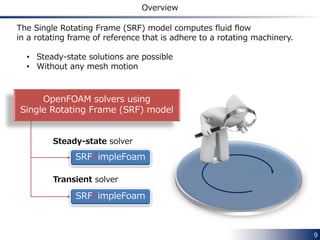
![16
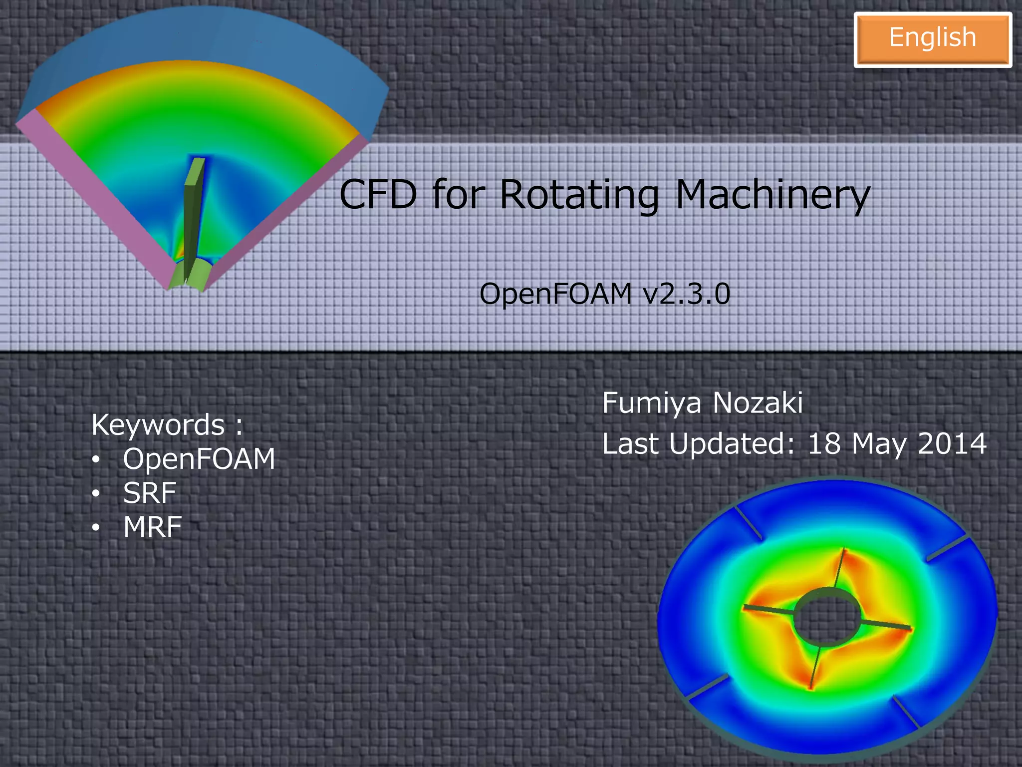
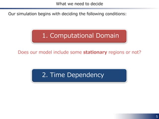
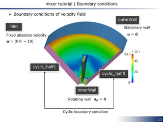
SRFProperties
Angular velocity condition is described in SRFProperties file.
/*--------------------------------*- C++ -*----------------------------------*¥
| ========= | |
| ¥¥ / F ield | OpenFOAM: The Open Source CFD Toolbox |
| ¥¥ / O peration | Version: 2.3.0 |
| ¥¥ / A nd | Web: www.OpenFOAM.org |
| ¥¥/ M anipulation | |
¥*---------------------------------------------------------------------------*/
FoamFile
{
version 2.0;
format ascii;
class dictionary;
location "constant";
object SRFProperties;
}
// * * * * * * * * * * * * * * * * * * * * * * * * * * * * * * * * * * * * * //
SRFModel rpm;
axis ( 0 0 1 );
rpmCoeffs
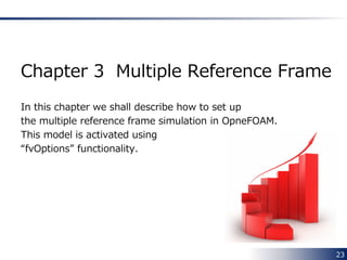
{
rpm 5000;
}
// ************************************************************************* //
Angular velocity is specified
in terms of revolutions-per-minute [rpm]
Axis of rotation
5000 rpm ⇒ 5000 ∗ 2π 60 = 523.6 [rad/s]
When the axis vector points to you
• rpm>0 ⇒ rotation in counterclockwise direction
• rpm<0 ⇒ rotation in clockwise direction
Rotational direction](https://image.slidesharecdn.com/openfoamrotatinggeometryenglish20140518-140517222323-phpapp01/85/CFD-for-Rotating-Machinery-using-OpenFOAM-16-320.jpg)
![18
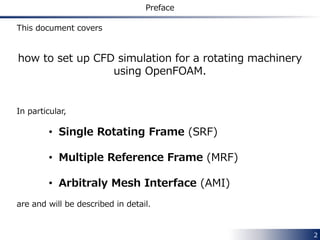
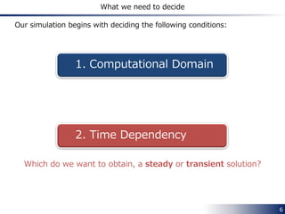
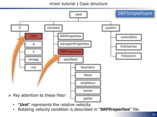
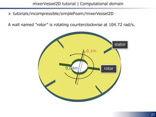
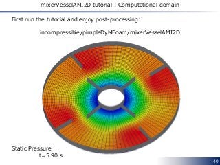
Closer look at the velocity on outerWall
In the stationary coordinate system
In the rotating coordinate system
Radius of outerWall is 0.1 m
𝒖𝐼 = 𝟎
𝒖 𝒓 = 𝒖𝐼 − 𝛀 × 𝒓
= 523.6 ∙ 0.1 = 52.36 [𝑚/𝑠]
Vectors show 𝒖 𝑟
Rotational direction](https://image.slidesharecdn.com/openfoamrotatinggeometryenglish20140518-140517222323-phpapp01/85/CFD-for-Rotating-Machinery-using-OpenFOAM-18-320.jpg)
![29
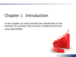
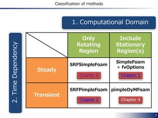
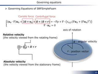
Governing equations
𝛻 ∙ 𝒖 𝑅 𝒖𝐼 + 𝛀 × 𝒖𝐼 = −𝛻𝑝 + 𝛻 ∙ 𝜈 𝑒𝑓𝑓 𝛻𝒖𝐼 + 𝛻𝒖𝐼
𝑇
𝛻 ∙ 𝒖 𝑅 = 0
In each rotating zone
• the Coriolis force is added to the governing equations
• the flux is calculated from the relative velocity 𝒖 𝑅
Governing equations [1]
Coriolis force
𝛻 ∙ 𝒖𝐼 𝒖𝐼 − 𝛀 × 𝒖 = −𝛻𝑝 + 𝛻 ∙ 𝜈 𝑒𝑓𝑓 𝛻𝒖𝐼 + 𝛻𝒖𝐼
𝑇
𝛻 ∙ 𝒖𝐼 = 0
Rotating zone
Stationary zone
1
2
1
2](https://image.slidesharecdn.com/openfoamrotatinggeometryenglish20140518-140517222323-phpapp01/85/CFD-for-Rotating-Machinery-using-OpenFOAM-29-320.jpg)
![34
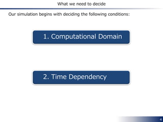
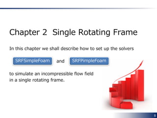
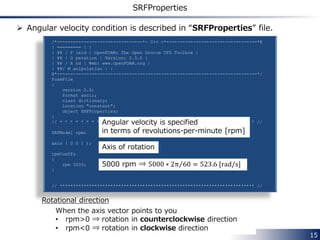
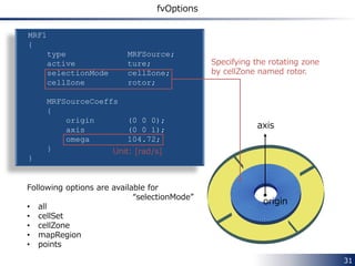
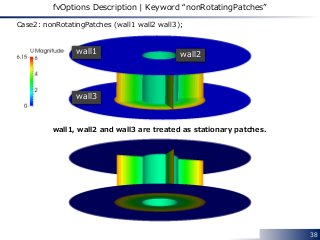
fvOptions Description
MRF1
{
type MRFSource;
active ture;
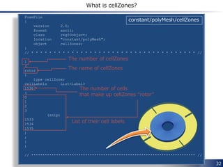
selectionMode cellZone;
cellZone rotor;
MRFSourceCoeffs
{
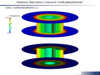
nonRotatingPatches ();
origin (0 0 0);
axis (0 0 1);
omega 104.72;
}
}
Specifying the rotating zone
by cellZone named rotor.
Unit: [rad/s]
axis
Following options are available for
“selectionMode”
• all
• cellSet
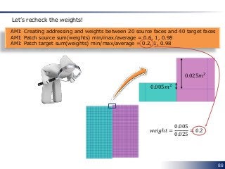
• cellZone
• mapRegion
• points
origin
system/fvOptions](https://image.slidesharecdn.com/openfoamrotatinggeometryenglish20140518-140517222323-phpapp01/85/CFD-for-Rotating-Machinery-using-OpenFOAM-34-320.jpg)

![void Foam::MRFZone::addCoriolis(fvVectorMatrix& UEqn, const bool rhs) const
{
if (cellZoneID_ == -1)
{
return;
}
const labelList& cells = mesh_.cellZones()[cellZoneID_];
const scalarField& V = mesh_.V();
vectorField& Usource = UEqn.source();
const vectorField& U = UEqn.psi();
const vector Omega = this->Omega();
if (rhs)
{
forAll(cells, i)
{
label celli = cells[i];
Usource[celli] += V[celli]*(Omega ^ U[celli]);
}
}
else
{
forAll(cells, i)
{
label celli = cells[i];
Usource[celli] -= V[celli]*(Omega ^ U[celli]);
}
}
}
41
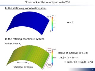
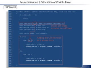
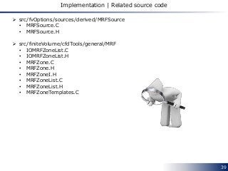
Implementation | Calculation of Coriolis force
List of cell labels
included in the cell zone
Adding the Coriolis force
to the right-hand
side as a source term
−𝛀 × 𝒖
src/finiteVolume/cfdTools/general/MRF/MRFZone.C](https://image.slidesharecdn.com/openfoamrotatinggeometryenglish20140518-140517222323-phpapp01/85/CFD-for-Rotating-Machinery-using-OpenFOAM-41-320.jpg)
![42
Implementation | Calculation of face flux
Classify all faces into three groups (faceType = 0, 1, 2)
• For internal faces
void Foam::MRFZone::setMRFFaces()
{
const polyBoundaryMesh& patches = mesh_.boundaryMesh();
labelList faceType(mesh_.nFaces(), 0);
const labelList& own = mesh_.faceOwner();
const labelList& nei = mesh_.faceNeighbour();
// Cells in zone
boolList zoneCell(mesh_.nCells(), false);
if (cellZoneID_ != -1)
{
const labelList& cellLabels = mesh_.cellZones()[cellZoneID_];
forAll(cellLabels, i)
{
zoneCell[cellLabels[i]] = true;
}
}
label nZoneFaces = 0;
for (label faceI = 0; faceI < mesh_.nInternalFaces(); faceI++)
{
if (zoneCell[own[faceI]] || zoneCell[nei[faceI]])
{
faceType[faceI] = 1;
nZoneFaces++;
}
}
faceType = 1
Either owner or neighbour cell
is in the cell zone
src/finiteVolume/cfdTools/general/MRF/MRFZone.C](https://image.slidesharecdn.com/openfoamrotatinggeometryenglish20140518-140517222323-phpapp01/85/CFD-for-Rotating-Machinery-using-OpenFOAM-42-320.jpg)
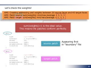
![43
Implementation | Calculation of face flux
• For boundary faces
labelHashSet excludedPatches(excludedPatchLabels_);
forAll(patches, patchI)
{
const polyPatch& pp = patches[patchI];
if (pp.coupled() || excludedPatches.found(patchI))
{
forAll(pp, i)
{
label faceI = pp.start()+i;
if (zoneCell[own[faceI]])
{
faceType[faceI] = 2;
nZoneFaces++;
}
}
}
else if (!isA<emptyPolyPatch>(pp))
{
forAll(pp, i)
{
label faceI = pp.start()+i;
if (zoneCell[own[faceI]])
{
faceType[faceI] = 1;
nZoneFaces++;
}
}
}
}
Coupled patch face
or excluded patch face
whose owner cell is
in the cell zone
Normal patch face
whose owner cell is
in the cell zone
faceType = 2
faceType = 1](https://image.slidesharecdn.com/openfoamrotatinggeometryenglish20140518-140517222323-phpapp01/85/CFD-for-Rotating-Machinery-using-OpenFOAM-43-320.jpg)
![44
Implementation | Calculation of face flux
Create two lists of face labels per patch
//- Outside faces (per patch) that move with the MRF
labelListList includedFaces_;
//- Excluded faces (per patch) that do not move with the MRF
labelListList excludedFaces_;
forAll(patches, patchi)
{
const polyPatch& pp = patches[patchi];
forAll(pp, patchFacei)
{
label faceI = pp.start() + patchFacei;
if (faceType[faceI] == 1)
{
includedFaces_[patchi][nIncludedFaces[patchi]++] = patchFacei;
}
else if (faceType[faceI] == 2)
{
excludedFaces_[patchi][nExcludedFaces[patchi]++] = patchFacei;
}
}
}
includedFaces_[patchi][i] = local label of ith face whose faceType = 1
on the patchith patch
excludedFaces_[patchi][i] = local label of ith face whose faceType = 2
on the patchith patch
src/finiteVolume/cfdTools/general/MRF/MRFZone.C](https://image.slidesharecdn.com/openfoamrotatinggeometryenglish20140518-140517222323-phpapp01/85/CFD-for-Rotating-Machinery-using-OpenFOAM-44-320.jpg)
.makeRelative(phi);
}
} src/fvOptions/fvOptions/fvOptionList.C
void Foam::fv::MRFSource::makeRelative(surfaceScalarField& phi) const
{
mrfPtr_->makeRelative(phi);
} src/fvOptions/sources/derived/MRFSource/MRFSource.C
void Foam::MRFZone::makeRelative(surfaceScalarField& phi) const
{
makeRelativeRhoFlux(geometricOneField(), phi);
}
src/finiteVolume/cfdTools/general/MRF/MRFZone.C](https://image.slidesharecdn.com/openfoamrotatinggeometryenglish20140518-140517222323-phpapp01/85/CFD-for-Rotating-Machinery-using-OpenFOAM-45-320.jpg)
![46
Implementation | Calculation of face flux
template<class RhoFieldType>
void Foam::MRFZone::makeRelativeRhoFlux
(
const RhoFieldType& rho,
surfaceScalarField& phi
) const
{
const surfaceVectorField& Cf = mesh_.Cf();
const surfaceVectorField& Sf = mesh_.Sf();
const vector Omega = omega_->value(mesh_.time().timeOutputValue())*axis_;
const vectorField& Cfi = Cf.internalField();
const vectorField& Sfi = Sf.internalField();
scalarField& phii = phi.internalField();
// Internal faces
forAll(internalFaces_, i)
{
label facei = internalFaces_[i];
phii[facei] -= rho[facei]*(Omega ^ (Cfi[facei] - origin_)) & Sfi[facei];
}
makeRelativeRhoFlux(rho.boundaryField(), phi.boundaryField());
}
src/finiteVolume/cfdTools/general/MRF/MRFZoneTemplates.C
Modification of the internal face flux
Modification of the
boundary face flux
• “internalFaces_” is a label list of the internal faces whose owner or neighbour
cell is in the rotating cell zone.
• According to the governing equation, the face fluxes of these internal faces
are modified by subtracting 𝜴 × 𝒓 ∙ 𝑺 𝑓 from the absolute face fluxes:
𝒖 𝑅 ∙ 𝑺 𝑓 = 𝒖𝐼 ∙ 𝑺 𝑓 − (𝜴 × 𝒓) ∙ 𝑺 𝑓](https://image.slidesharecdn.com/openfoamrotatinggeometryenglish20140518-140517222323-phpapp01/85/CFD-for-Rotating-Machinery-using-OpenFOAM-46-320.jpg)
![47
Implementation | Calculation of face flux
template<class RhoFieldType>
void Foam::MRFZone::makeRelativeRhoFlux
(
const RhoFieldType& rho,
FieldField<fvsPatchField, scalar>& phi
) const
{
const surfaceVectorField& Cf = mesh_.Cf();
const surfaceVectorField& Sf = mesh_.Sf();
const vector Omega = omega_->value(mesh_.time().timeOutputValue())*axis_;
// Included patches
forAll(includedFaces_, patchi)
{
forAll(includedFaces_[patchi], i)
{
label patchFacei = includedFaces_[patchi][i];
phi[patchi][patchFacei] = 0.0;
}
}
// Excluded patches
forAll(excludedFaces_, patchi)
{
forAll(excludedFaces_[patchi], i)
{
label patchFacei = excludedFaces_[patchi][i];
phi[patchi][patchFacei] -=
rho[patchi][patchFacei]
* (Omega ^ (Cf.boundaryField()[patchi][patchFacei] - origin_))
& Sf.boundaryField()[patchi][patchFacei];
}
}
}
src/finiteVolume/cfdTools/general/MRF/MRFZoneTemplates.C
Relative face fluxes
on rotating patches are zero
𝒖 𝑅 ∙ 𝑺 𝑓 = 0
Relative face fluxes
on stationary patches
in the rotating cell zone
is calculated by subtracting
𝜴 × 𝒓 ∙ 𝑺 𝑓 from the absolute
face fluxes](https://image.slidesharecdn.com/openfoamrotatinggeometryenglish20140518-140517222323-phpapp01/85/CFD-for-Rotating-Machinery-using-OpenFOAM-47-320.jpg)


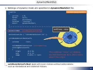
![63
solidBodyMotionFvMesh
The following motions (solidBodyMotionFunction) are available for
solidBodyMotionFvMesh
• linearMotion
• oscillatingLinearMotion
• rotatingMotion
• axisRotationMotion
• oscillatingRotatingMotion
• SDA [4]
• multiMotion
Code: src/dynamicFvMesh/solidBodyMotionFvMesh/solidBodyMotionFunctions
Translational motion
Rotational motion
Ship Design Analysis
Combination of the above motions](https://image.slidesharecdn.com/openfoamrotatinggeometryenglish20140518-140517222323-phpapp01/85/CFD-for-Rotating-Machinery-using-OpenFOAM-63-320.jpg)
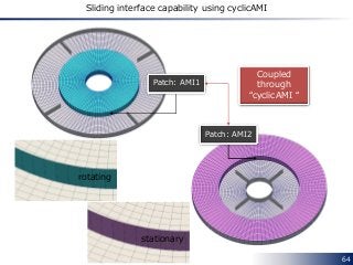
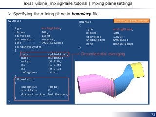
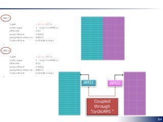
![ What is the ribbonPatch? [5]
According to [6]
the ribbon patch will specify the direction in which it will perform the
average (sweepAxis) and in which direction it will stack the cells
(stackAxis).
75
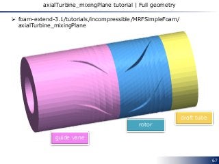
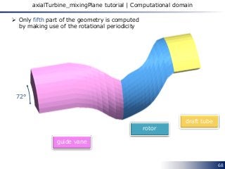
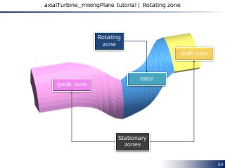
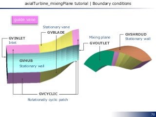
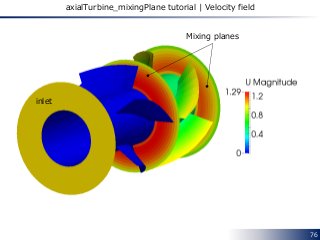
axialTurbine_mixingPlane tutorial | Mixing plane settings
ribbonPatch
{
sweepAxis Theta;
stackAxis R;
discretisation bothPatches;
}
R
Theta](https://image.slidesharecdn.com/openfoamrotatinggeometryenglish20140518-140517222323-phpapp01/85/CFD-for-Rotating-Machinery-using-OpenFOAM-75-320.jpg)
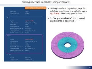
![77
axialTurbine_mixingPlane tutorial | MRFZones
1
(
rotor
{
// Fixed patches (by default they 'move' with the MRF zone)
nonRotatingPatches ( RUSHROUD );
origin origin [0 1 0 0 0 0 0] (0 0 0);
axis axis [0 0 0 0 0 0 0] (0 0 1);
omega omega [0 0 -1 0 0 0 0] -10;
}
)
Specifying the rotating zone in MRFZones file
rotor
Name of rotating cellZones
The absolute velocity on the
“nonRotatingPatches” is 0.
constant/MRFZones](https://image.slidesharecdn.com/openfoamrotatinggeometryenglish20140518-140517222323-phpapp01/85/CFD-for-Rotating-Machinery-using-OpenFOAM-77-320.jpg)
![78
History of development
[7]](https://image.slidesharecdn.com/openfoamrotatinggeometryenglish20140518-140517222323-phpapp01/85/CFD-for-Rotating-Machinery-using-OpenFOAM-78-320.jpg)
![81
References
[1] http://openfoamwiki.net/index.php/See_the_MRF_development
[2] CFD for Underhood Modeling
http://publications.lib.chalmers.se/records/fulltext/204821/204821.pdf
[3] http://www.sourceflux.de/blog/software-design-fvoptions/
[4] Roll Motion of a Box and Interaction with Free-Surface
http://www.tfd.chalmers.se/~hani/kurser/OS_CFD_2009/ArashEslamdoost/RollMotionofaBoxa
ndInteractionwithFreeSurface.pdf
[5] Martin Beaudoin, Inside the mixingPlane interface
ftp://ftp.heanet.ie/disk1/sourceforge/o/op/openfoam-
extend/OpenFOAM_Workshops/OFW7_2012_Darmstadt/Workshop-
Documents/CommunityDay/SIG-Turbo/Final-MartinBeaudoin-
OFTurboWGInsideTheMixingPlaneInterfac (accessed 06/13/2015)
[6] Ant´onio Jo˜ao Ferreira Reis, Validation of NASA Rotor 67 with OpenFOAM’s Transonic
Density-Based solver
http://run.unl.pt/bitstream/10362/9930/1/Reis_2013.pdf (accessed 06/13/2015)
[7] Evaluation of an improved mixing plane interface for OpenFOAM
http://publications.lib.chalmers.se/records/fulltext/201855/local_201855.pdf
[8] Taking the mixingPlane interface for a ride
http://download2.polytechnic.edu.na/pub4/sourceforge/o/op/openfoam-
extend/OpenFOAM_Workshops/OFW9_2014_Zagreb/Presentations/Hakan_Nilsson_OFW09_P_
0046.pdf](https://image.slidesharecdn.com/openfoamrotatinggeometryenglish20140518-140517222323-phpapp01/85/CFD-for-Rotating-Machinery-using-OpenFOAM-81-320.jpg)
![82
References
[9] Density Based Navier Stokes Solver for Transonic Flows
http://www.personal.psu.edu/dab143/OFW6/Presentations/oliver_borm_slides.pdf](https://image.slidesharecdn.com/openfoamrotatinggeometryenglish20140518-140517222323-phpapp01/85/CFD-for-Rotating-Machinery-using-OpenFOAM-82-320.jpg)


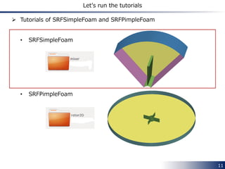
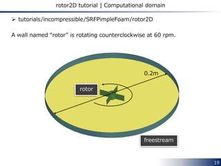
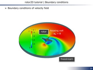
This document discusses setting up CFD simulations for rotating machinery using OpenFOAM. It describes the Single Rotating Frame (SRF) and Multiple Reference Frame (MRF) methods. The SRF method computes the flow in a single rotating frame of reference attached to the rotating machinery, allowing for steady-state or transient solutions without mesh motion. The MRF method computes the flow using both rotating and stationary frames, with the rotating zone solved in the rotating frame and stationary zones in the stationary frame. Tutorial cases for the SRF solvers SRFSimpleFoam and SRFPimpleFoam are presented to demonstrate implementing rotating boundary conditions and calculating additional force terms.