Download to read offline
![IJRET: International Journal of Research in Engineering and Technology eISSN: 2319-1163 | pISSN: 2321-7308
_______________________________________________________________________________________
Volume: 04 Issue: 01 | Jan-2015, Available @ http://www.ijret.org 294
NUMERICAL STUDY OF DISK DRIVE ROTATING FLOW
STRUCTURE IN THE CAVITY
Kwan Ouyang1
, Reui-Kuo Lin2
, Shun-Feng Tsai3
1
Associate Professor, Department of Marine Engineering, Taipei College of Maritime Technology, Taipei, Taiwan,
Republic of China (R.O.C.)
2
Assistant Professor, Department of Marine Engineering, Taipei College of Maritime Technology, Taipei, Taiwan,
Republic of China (R.O.C.)
3
Assistant Professor, Department of Marine Engineering, National Taiwan Ocean University, Keelung, Taiwan,
Republic of China (R.O.C.)
Abstract
This paper aim in conducting the numerical simulation of laminar flow to explore disk-driven vortical flow structure of a cubical
container subjected to a disk rotation on the roof of the container in different Reynolds numbers to observe the flow structure and
the reason of vortical flow form. For this study, finite difference method with dispersion-relation- preserving (DRP) scheme is
dispersed governing equations space term, but adopt time term with TVD Runge-Kutta method. To add accuracy of numerical,
this thesis also uses topology theory to analyze the characteristic of singular point. Three-dimensional vertical flow is observed
flow structure and move to condition. The result to obtain Reynolds numbers to increase attracting spiral nodes increasingly
approaches the floor of the cavity. We have also depicted the vertical flow structure in terms of cortex cores which provide more
details about how change of the Reynolds number
Keywords: disk-driven, finite difference method, dispersion-relation-preserving (DRP), Runge-Kutta, topology theory
---------------------------------------------------------------------***---------------------------------------------------------------------
1. INTRODUCTION
Numerical simulation is based on mathematical rules,
computer technology, engineering and related disciplines of
professional. From the school gate, in recent years, due to
advances in computer hardware and software, numerical
calculation method improved physical problems for more
accurate analytical results. Numerical calculations have been
widely used in the field of physics, chemistry, fluid
dynamics, atmospheric science, aerospace, and industrial
applications such as solid mechanics. Hydrodynamics is part
of mechanics and it is mainly Fluid (including gas and
liquid) scientific phenomena and related mechanical
behavior of subjects may be divided into sports mode
hydrostatic and hydrodynamic. Fluid mechanics research is
based on Newton's laws of motion and conservation of mass
law, often have to use the knowledge of thermodynamics,
and sometimes used the basic laws of macroscopic
dynamics equations and physics, basic knowledge of
chemistry.
Transmission problems, such as blade design fluid
machinery, ships and aircraft design, engine design, reaction
tank design, and even the semiconductor manufacturing
process, such as sputtering or evaporation analysis covers a
very wide range of applications. And in addition to this
analysis tools adapted to explore the impact of parameter
changes, but because of the established analytical database,
and more able to reduce the man-hours required for the
experiment and shorten design time away. With the progress
of the update and the calculation method of computer
hardware and software technology, the use of computational
fluid dynamics to explore the physical world of the fluid, not
only has been widely used by scholars, have become the
industry to solve engineering problems related to a major
weapon. Today, computational fluid dynamics and
theoretical mechanics, fluid dynamics experiments
constituted the largest modern mainstream research in fluid
mechanics. Has developed a finite difference method, finite
element method, finite volume method, spectral method and
Sim algorithms, coupled with the vigorous development of
computer technology now makes the CPU computational
efficiency, memory capacity, storage devices, operating
systems and network auxiliary parallel computing, and other
peripheral functions under that CFD is widely applied to
almost all parts of the field of fluid dynamics.
In the past the process industries often use to drive the
rotating disc cylinder or rectangular, thereby to understand
the internal structure of the flow field. Applying a simple
geometric structure of the flow field to explore rotation can
help analyze and understand the principles of early and
recent research literature mostly cylindrical or rectangular
shape, so this article is to explore the use of a cube shape, in
their daily lives the most common is the computer's CD-
ROM drive, using a rotary disc pieces to bring the whole
flow field, hoping to apply the same theory to understand
the internal structure of the flow field, the paper is a
continuation of the literature Chiang [12] study was done to
continue to explore when > 2000 the structure of the
flow field generated.](https://image.slidesharecdn.com/numericalstudyofdiskdriverotatingflowstructureinthecavity-160829105754/85/Numerical-study-of-disk-drive-rotating-flow-structure-in-the-cavity-1-320.jpg)
![IJRET: International Journal of Research in Engineering and Technology eISSN: 2319-1163 | pISSN: 2321-7308
_______________________________________________________________________________________
Volume: 04 Issue: 01 | Jan-2015, Available @ http://www.ijret.org 294
NUMERICAL STUDY OF DISK DRIVE ROTATING FLOW
STRUCTURE IN THE CAVITY
Kwan Ouyang1
, Reui-Kuo Lin2
, Shun-Feng Tsai3
1
Associate Professor, Department of Marine Engineering, Taipei College of Maritime Technology, Taipei, Taiwan,
Republic of China (R.O.C.)
2
Assistant Professor, Department of Marine Engineering, Taipei College of Maritime Technology, Taipei, Taiwan,
Republic of China (R.O.C.)
3
Assistant Professor, Department of Marine Engineering, National Taiwan Ocean University, Keelung, Taiwan,
Republic of China (R.O.C.)
Abstract
This paper aim in conducting the numerical simulation of laminar flow to explore disk-driven vortical flow structure of a cubical
container subjected to a disk rotation on the roof of the container in different Reynolds numbers to observe the flow structure and
the reason of vortical flow form. For this study, finite difference method with dispersion-relation- preserving (DRP) scheme is
dispersed governing equations space term, but adopt time term with TVD Runge-Kutta method. To add accuracy of numerical,
this thesis also uses topology theory to analyze the characteristic of singular point. Three-dimensional vertical flow is observed
flow structure and move to condition. The result to obtain Reynolds numbers to increase attracting spiral nodes increasingly
approaches the floor of the cavity. We have also depicted the vertical flow structure in terms of cortex cores which provide more
details about how change of the Reynolds number
Keywords: disk-driven, finite difference method, dispersion-relation-preserving (DRP), Runge-Kutta, topology theory
---------------------------------------------------------------------***---------------------------------------------------------------------
1. INTRODUCTION
Numerical simulation is based on mathematical rules,
computer technology, engineering and related disciplines of
professional. From the school gate, in recent years, due to
advances in computer hardware and software, numerical
calculation method improved physical problems for more
accurate analytical results. Numerical calculations have been
widely used in the field of physics, chemistry, fluid
dynamics, atmospheric science, aerospace, and industrial
applications such as solid mechanics. Hydrodynamics is part
of mechanics and it is mainly Fluid (including gas and
liquid) scientific phenomena and related mechanical
behavior of subjects may be divided into sports mode
hydrostatic and hydrodynamic. Fluid mechanics research is
based on Newton's laws of motion and conservation of mass
law, often have to use the knowledge of thermodynamics,
and sometimes used the basic laws of macroscopic
dynamics equations and physics, basic knowledge of
chemistry.
Transmission problems, such as blade design fluid
machinery, ships and aircraft design, engine design, reaction
tank design, and even the semiconductor manufacturing
process, such as sputtering or evaporation analysis covers a
very wide range of applications. And in addition to this
analysis tools adapted to explore the impact of parameter
changes, but because of the established analytical database,
and more able to reduce the man-hours required for the
experiment and shorten design time away. With the progress
of the update and the calculation method of computer
hardware and software technology, the use of computational
fluid dynamics to explore the physical world of the fluid, not
only has been widely used by scholars, have become the
industry to solve engineering problems related to a major
weapon. Today, computational fluid dynamics and
theoretical mechanics, fluid dynamics experiments
constituted the largest modern mainstream research in fluid
mechanics. Has developed a finite difference method, finite
element method, finite volume method, spectral method and
Sim algorithms, coupled with the vigorous development of
computer technology now makes the CPU computational
efficiency, memory capacity, storage devices, operating
systems and network auxiliary parallel computing, and other
peripheral functions under that CFD is widely applied to
almost all parts of the field of fluid dynamics.
In the past the process industries often use to drive the
rotating disc cylinder or rectangular, thereby to understand
the internal structure of the flow field. Applying a simple
geometric structure of the flow field to explore rotation can
help analyze and understand the principles of early and
recent research literature mostly cylindrical or rectangular
shape, so this article is to explore the use of a cube shape, in
their daily lives the most common is the computer's CD-
ROM drive, using a rotary disc pieces to bring the whole
flow field, hoping to apply the same theory to understand
the internal structure of the flow field, the paper is a
continuation of the literature Chiang [12] study was done to
continue to explore when > 2000 the structure of the
flow field generated.](https://image.slidesharecdn.com/numericalstudyofdiskdriverotatingflowstructureinthecavity-160829105754/75/Numerical-study-of-disk-drive-rotating-flow-structure-in-the-cavity-1-2048.jpg)
![IJRET: International Journal of Research in Engineering and Technology eISSN: 2319-1163 | pISSN: 2321-7308
_______________________________________________________________________________________
Volume: 04 Issue: 01 | Jan-2015, Available @ http://www.ijret.org 295
Benjamin and Denny [1] in 1979 with the vorticity-stream
function method to simulate the two-dimensional closed pull
hole course and supplemented with multi-grid method, the
first to raise the numerical simulation of the Reynolds
number to 104, expressly found that the two-dimensional
closed pull hole course is located in the geometric center of
the main vortex with three corners of the second vortex.
Ostrach [3] in 1972 experimentally observed velocity
distribution in the cavity exhibits antisymmetric, but the
viscosity coefficient is a function of temperature, in a small
wall near the thermal boundary layer of fluid, large speed.
Fenstermacher [4] in 1979, the use of laser-Doppler
velocimetry explore concentric circles in the middle of the
restricted fluid from the column of rotating flow generated
by the transitional situation. Chenoweth and Paolucci [5] in
1986 as well as Dennis and Hudson [6] in 1989 to study the
solid wall boundary movement along the border and around
the hole center of rotation.
Goharzadeh and Mutabazi [13] in 2001, the study is to
explore is reversed between concentric cylinders, in
Couette-Taylor system, the experimental characteristics of
intermittent flow conditions. Disturbed flow conditions, the
study found that even two-cylinder turbulence in part
dependent on the speed with the speed of increase
turbulence and then evolved into a spiral turbulence,
turbulence generated by its spiral speed when using the
control parameters, in order to observe the reverse cylinder
axial velocity dependent on the speed of the outside of the
column. Okulov, Meledin and Naumov [14] in 2003, when
at =1500-6000 cube rotating disc plus tip vortex
experimental studies, when is greater than 4000 will
have a spiral shape vortex core disintegration will produce
steady flow field (unsteady flow) phenomenon. Sparrow and
Abraham [15] mentioned assumptions virtual density in
2003, will lead to numerical errors, so the momentum
equation calculations, based on the direct method for solving
the momentum Fang Cheng style. And referred to the closed
cavity natural convection, fluid flow is not only caused by
the density difference, we must consider the impact of
pressure on the flow field. Doby, Nowakowski and
Dyakowski [16] in 2007 to study for a cylindrical vortex
flow generated by adding a rotating cover using
experimental and numerical methods.
This paper is divided into five chapters, are outlined as
follows: Section 2 for the physical and mathematical model,
a brief governing equations used herein, the governing
equation is substituted into the hypothetical dimensionless
parameters, push dimensionless equations, assuming that the
boundary conditions. In section 3, the numerical square
model, numerical methods used in this paper is to keep the
format of the dispersion relation to reduce the error of the
convective terms, and then using the finite difference
method to illustrate the problem with the program
verification. Section 4, the numerical results are plotted in
figure flow field and for the impact caused by the different
number Re discuss research. Finally section, the comparing
the results obtained for the post and then make a summary
statement of results and the contribution of this chapter.
2. NUMERICAL MODEL
This article assumes that the entire flow field for
incompressible flow (incompressible flow), all are all three-
dimensional flow field flow field, Figure 1, the top has a
rotating disk, the disk radius equal to feature here length ,
maximum rotational speed of the disc is equal to the
characteristic velocity . The use of three-dimensional
Navier-Stokes equations transient Cartesian coordinate
system, the three-dimensional transient continuous equation,
momentum equation and energy equation is simplified as
follows:
(1)
(2)
The above two equations will be solved subject to the initial
divergence-free velocity condition and boundary velocities
to close the problem. In this primitive-variable formulation,
specification of velocity boundary conditions has been
rigorously proven.
A small and smooth change of the parameter value (or
in the currently investigated differential system) may cause
a sudden qualitative or topological change in the system
equilibrium. Under the circumstances, we call that
bifurcation initiates. According to the theory of bifurcation,
which is in association with the local solution behaviors of
nonlinear equation in the neighbor of a known solution of
the equation, bifurcations can be divided into the local and
global types. Local bifurcations are mathematically
associated with the real part of the eigenvalues of an
equilibrium which passes through zero. Local bifurcation,
which includes pitchfork, Hopf, saddle-node (or tangent or
blue sky), periodic-doubling (flip), secondary Hopf
(Neimark), and transcritical bifurcations, occurs when the
Reynolds number change causes the stability of an
equilibrium to change. Since only the local bifurcation type
has been found in this study in the present nonlinear system,
no global bifurcation will be dealt with herein.
2.1 Dispersion-Relation-Preserving (DRP) Scheme
Finite difference method (FDM) is a method used to
calculate the numerical simulation of the oldest, is still
widely used. Partial differential equations to be solved, by
Taylor expansion, the direct control of discrete equations,
which are covered by the concept of localized discrete. For
the finite difference scheme, from precision format to
points, there is a first-order scheme, second order and
higher-order format. From space to consider the differential
form, can be divided into the center format and upwind
format. Consider the impact of the time factor; the
difference scheme can also be divided into explicit form,
implicit schemes, explicit and implicit alternate format.
Current common difference scheme, mainly in the form of a
combination of the several different combinations constitute](https://image.slidesharecdn.com/numericalstudyofdiskdriverotatingflowstructureinthecavity-160829105754/85/Numerical-study-of-disk-drive-rotating-flow-structure-in-the-cavity-2-320.jpg)
![IJRET: International Journal of Research in Engineering and Technology eISSN: 2319-1163 | pISSN: 2321-7308
_______________________________________________________________________________________
Volume: 04 Issue: 01 | Jan-2015, Available @ http://www.ijret.org 296
different differential formats. There are many ways
constitute a difference, now mainly used in the Taylor series
expansion method. The basic differential expression of three
major forms: first-order forward difference, first-order
backward difference, first-order and second-order central
difference central difference, of which the first two formats
for the first-order accuracy, the latter two formats for the
second-order calculation accuracy. The main disadvantage
of the finite difference method is poor and the applicability
of the numerical solution of complex conservation area is
difficult to ensure, so this part of the diffusion terms in the
discrete second order accurate difference method middle.
Fig-1: Description of the investigated natural-convection
problem and the uniform grid distribution on the bounding
surfaces.
In the past literature, by Tam and Webb put forward
dispersion relations have maintained format (dispersion-
relation-preserving scheme, hereinafter referred to as DRP
format), use of best spatial discrete methods to increase the
number of analog format on the wave power. The idea is to
assume the function of a Fourier transformation, then the
Fourier converted. The corresponding difference scheme
inevitably transformed with the presence of poor guide.
DRP format while maintaining a certain accuracy of the
premise, to make such a poor dispersion coefficient
optimization guide smallest, reduce errors convection term.
2.3 Total Variation Diminishing (TVD) Scheme
Total variation diminishing (TVD) scheme is proposed by
Harten et al., TVD format is a semi-discrete scheme up to
reach the second-order accurate precision. But the critical
point will be reduced to first-order accuracy, and therefore
Harten and Osher et al ENO (Essentially Non-Oscillatory)
format, thereby improving the accuracy and characteristics
of TVD scheme does not oscillate, so that in any case TVD
format maintain high order accuracy.
Generally when solving ordinary differential equations,
according to the accuracy required to select the correlation
coefficient for a typical fourth-order accurate Runge-Kutta
explicit time integration count is concerned, then
select , , and
。Runge-Kutta count the count is compared
with Euler, although they may be bigger, but not necessarily
to calculate the total amount of savings, because solving the
main computational calculations, four times longer to be
calculated at each time step , but the opposite can’t is
increased 4 times. Runge-Kutta currently considered are
mainly used for high accuracy requirements on the issue.
3. NUMERICAL RESULTS
This is the top of the cube plus rotating disk drive, and to
explore the structure of the flow field, the continuation of
the literature Chiang [12] have done research, more in-depth
discussion the case when the Reynolds number flow field to
increase the structural change, and learn about their physical
phenomenon occurs. The numerical results obtained in this
article essays Fortran programs found at the top of the
rotation when > 4800 will produce unstable flow
(unsteady), both up and down the rotation is will
produce 4000, so this article is divided into three parts to
investigate, the first part is a steady flow (steady) = 500,
2000, 2500, 3000, 3500 and 4000 taken for analysis. The
second part is the unstable flow, its velocity, pressure, flow
structure will change over time, so this takes time to analyze
= 7000. The last part of the rotation of the upper and
lower case, =5000 to take can take to analyze for
comparison with the second part.
3.1 Steady Flow Structural Analysis Field
This paper discusses the first to enter, the talk in the past of
literature than to be right, to learn about the applicability and
accuracy of the numerical Figure 1 Chiang literature of
comparison, the figure can be learned from a slight gap
between the reason may be is the number of different grid
use, so different numerical methods used so causing a slight
error. Figure 2 is compared with the results of experiments
done right, can be learned from the figure when =2000,
little error at =4000, then it is open to explore entering
this article.](https://image.slidesharecdn.com/numericalstudyofdiskdriverotatingflowstructureinthecavity-160829105754/85/Numerical-study-of-disk-drive-rotating-flow-structure-in-the-cavity-3-320.jpg)
![IJRET: International Journal of Research in Engineering and Technology eISSN: 2319-1163 | pISSN: 2321-7308
_______________________________________________________________________________________
Volume: 04 Issue: 01 | Jan-2015, Available @ http://www.ijret.org 302
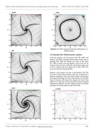
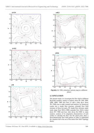
Fig-6(c): Re=500 (z direction pressure diagram on different
faces)
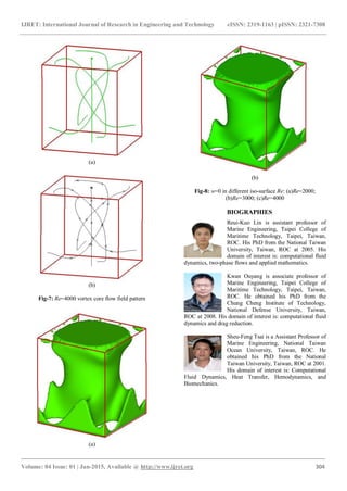
ACKNOWLEDGEMENTS
The financial supports provided by the Ministry of Science
and Technology (MOST) under grants MOST 102-2221-E-
229-001 and MOST102-2119-M-492-004 are gratefully
acknowledged.
REFERENCES
[1] T. P. Chiang, W. H. Sheu, S. F. Tsai, Disk-driven
vortical flow structure in a cubical container,
Computers & Fluid., Vol. 28:41-61(1999).
[2] Christopher K. W. Tam, Jay C. Webb, “Dispersion-
relation-preserving finite difference schemes for
computational acoustics, J. Comput. Phy., Vol. 107
:262-281(1993).
[3] Harten . A, Osher. S, Chakravarthy S. R.
“Uniformly high-order accurate essentially non-
oscillatory schemes 3”J. Comput. Phys., Vol. 71:
231-303(1987)
[4] A. S. Benjamin, V. E. Denny, On the convergence
of numerical solution for 2-D flows in a cavity at
large Re, J. Comput. Phys., Vol. 33 : 340-
358(1979).
[5] Takaji Inamuro, Akimasa Yamaguchi1 and
Fumimaru Ogino, Fluid flow in a rotating
cylindrical container with a rotating disk at the fluid
surface, Fluid Dynamics Research., Vol. 21:417-
430(1997).
[6] V. L. Okulov, V. G. Meledin, and I. V. Naumov,
Experimental Investigation of a Swirling Flow in a
Cubic Container, Technical Physics., Vol. 48 :
1249-1254(2003)
[7] A Harten, S Osher, SR Chakravarthy (1987)
Uniformly high-order accurate essentially non-
oscillatory schemes. J. Comput Phys, Vol. 71: 231-
303
[8] GD Thiart (1990) Finite difference scheme for the
numerical solution of fluid flow and heat transfer
problems on non-staggered grids, Numer Heat Tran,
Part B, Vol. 17: 43-62
[9] T Fusegi, JM Hyun, K Kuwahara, B Farouk (1991)
A numerical study of three-dimensional natural
convection in a differentially heated cubical
enclosure, Int. J. Heat Mass Transfer Vol. 34: 1543-
1557
[10] Christopher KW Tam, Jay C Webb (1993),
Dispersion-relation-preserving finite difference
schemes for computational acoustics, J. Comput.
Phys, Vol. 107: 262-281
[11] TL Lee, TF Lin (1996) Transient three-dimensional
convection of air in a differentially heated rotating
cubic cavity, Int. J. Heat Mass Transfer Vol. 39:
1243-1255
[12] YT Ker, TF Lin (1996) A combined numerical and
experimental study of air convection in a
differentially heated rotating cubic cavity, Int. J.
Heat Mass Transfer, Vol. 39: 3193-3210
[13] W Date (1993) Solution of Navier-Stokes equations
on non-staggered grids, Int. J. Heat and Mass
Transfer, Vol. 36: 1913-1922
[14] Shinichiro Wakashima, Takeo S Saitoh (2004)
Benchmark solutions for natural convection in a
cubic cavity using the high-order time-space
method, Int. J. Heat & Mass Tran, Vol. 47: 853-864
[15] C. Kuhlmann, M. Wanschura, H. J. Rath, Flow in
two-sided lid-driven cavity: Non-uniqueness,
instabilities, and cellular structures. J. Fluid Mech.,
336, 267-299, 1997
[16] S. V. Patanker, Numerical Heat Transfer and Fluid
Flow. Hemisphere, 1980
[17] A. Ladyzhenskaya, Mathematical Problems in the
Dynamics of a Viscous Incompressible Flow.
Gordon and Breach, New York, 1963
[18] S. Abdallah, Numerical solution for the
incompressible Navier-Stokes equations in primitive
variables using a non-satggered grid, II. J. Comput.
Phys. 70, 193-202, 1987
[19] P. H. Chiu, T. W. H. Sheu, R. K. Lin, Development
of a dispersion-relation-preserving upwinding
scheme for incompressible Navier-Stokes equations
on non-staggered grids. Numer. Heat Tran. Part B,
48(6), 543-569, 2005
[20] L. Quartapelle, M. Napolitano, Integral condtions
for the pressure in the computation of
incompressible viscous flows. J. Comput. Phys. 62,
340-348, 1986
[21] P. Lin, A sequential regularization method for time-
dependent incompressible Navier-Stokes equations.
SIAM J. Numer. Anal. 34(3), 1051-1071, 1997](https://image.slidesharecdn.com/numericalstudyofdiskdriverotatingflowstructureinthecavity-160829105754/85/Numerical-study-of-disk-drive-rotating-flow-structure-in-the-cavity-9-320.jpg)

This paper focuses on the numerical simulation of laminar flow in a cubical container with a rotating disk, exploring the resulting vortical flow structures at varying Reynolds numbers. It employs finite difference methods and topology theory to analyze the flow characteristics, emphasizing the effects of Reynolds number on flow patterns and stability. Results indicate significant changes in flow behavior as Reynolds numbers increase, leading to unstable and steady flow conditions that reflect the complex dynamics of rotating flow systems.