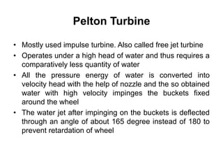
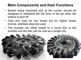
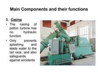
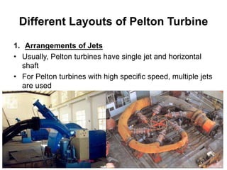
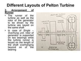
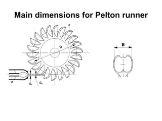
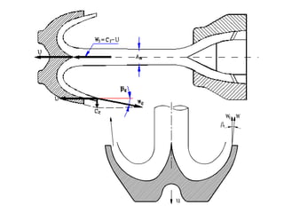
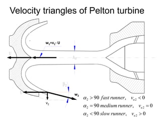
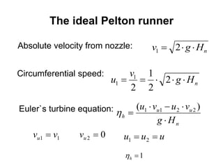
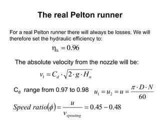
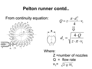
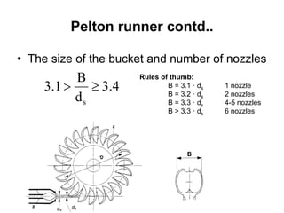
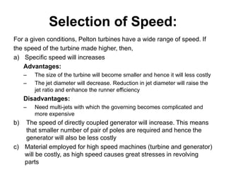
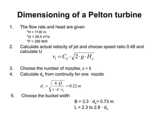
This document summarizes the key components and operation of a Pelton turbine. It begins by describing Pelton turbines as impulse turbines that operate under high head with a jet of water impinging on buckets around the wheel. It then discusses the main components of Pelton turbines including the guide mechanism, buckets and runner, and casing. The guide mechanism controls water flow to maintain constant wheel speed. Buckets are designed to deflect the jet and withstand impact forces. Various Pelton turbine layouts and dimensions are also covered. Formulas for speed number, hydraulic efficiency, and sample dimensioning calculations are provided.


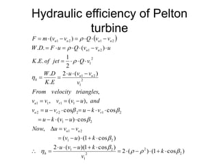
![Hydraulic efficiency of Pelton
turbine Contd..
• The power output becomes zero
when u = 0 and when u = v1
• First case the wheel is at rest and
second case the wheel runs at the
highest speed called runaway speed
• For maximum efficiency,
)cos1(
2
1
,
2
cos1
2
1
0)21(
0)cos1(2sin
0)cos1()21(2
0)]cos1()(2[
2
2
max
2
max
1
2
2
2
2
kklossesnozzleif
v
u
or
kce
kor
k
d
d
v
Practically, blade angle =
10-15 degree](https://image.slidesharecdn.com/4-190204081450/85/4-pelton-turbine-21-320.jpg)
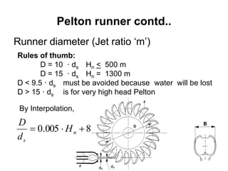
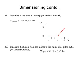
![Dimensioning contd..
6. Find the diameter by interpolation
mdD
H
d
D
s
n
s
0.365.13
65.138005.0
D/ds
Hn [m]
10
15
400 1400](https://image.slidesharecdn.com/4-190204081450/85/4-pelton-turbine-32-320.jpg)
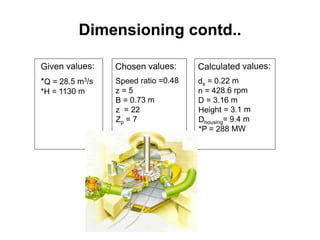
![Dimensioning contd..
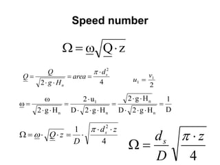
7. Calculate the speed:
8. Choose the number of poles on the generator:
The speed of the runner is given by the generator and the net frequency:
where Zp= pair of poles on the generator
The pair of poles will be:
rpm
D
u
n
DND
u
452
60
260
2
2
1
1
][
3000
rpm
Z
N
p
764.6
3000
N
Zp](https://image.slidesharecdn.com/4-190204081450/85/4-pelton-turbine-33-320.jpg)
![Dimensioning contd..
9. Recalculate the speed:
10. Recalculate the diameter:
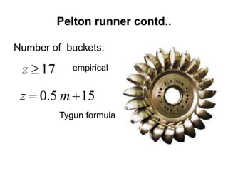
11. Choose the number of buckets
z = 22
][6.428
3000
rpm
Z
N
p
m
N
u
D
DND
u 16.3
60
260
2
2
1
1
](https://image.slidesharecdn.com/4-190204081450/85/4-pelton-turbine-34-320.jpg)