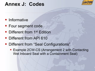
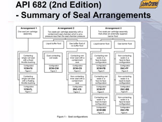
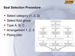
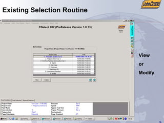
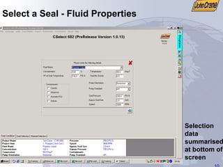
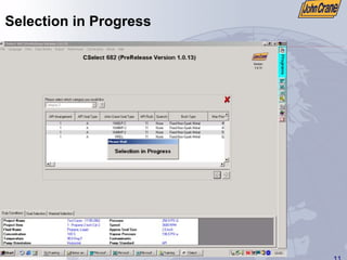
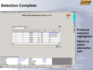
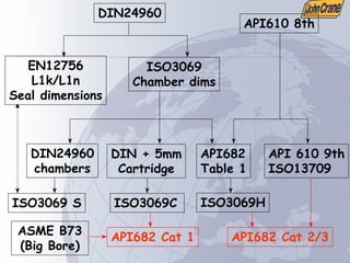
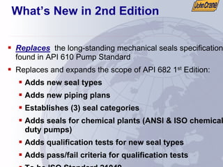
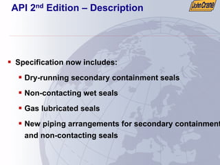
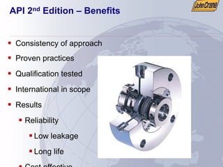
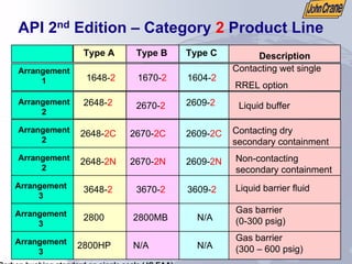
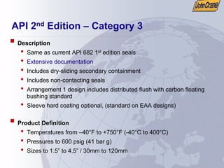
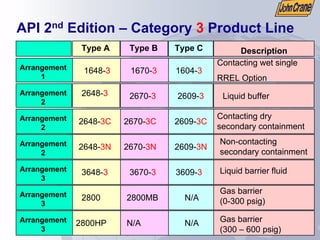
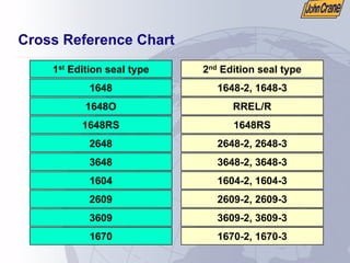
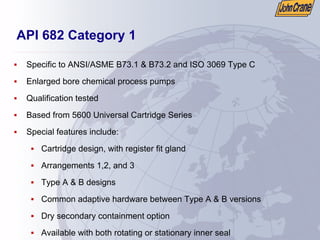
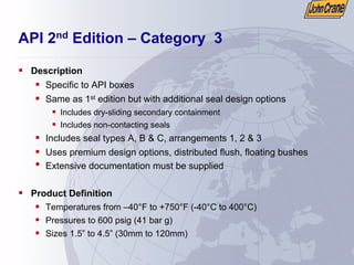
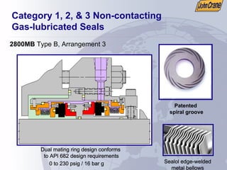
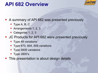
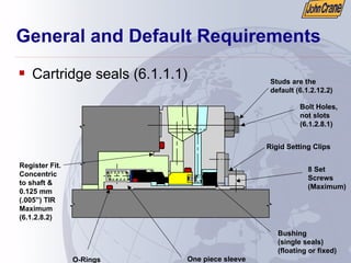
The document provides an overview of the American Petroleum Institute (API) 682 2nd Edition standard for shaft sealing systems for centrifugal and rotary pumps. It describes the purpose and benefits of the standard in promoting best practices for mechanical seal selection and operation. The standard establishes three seal categories and defines acceptable seal types, arrangements, operating ranges, and qualification testing requirements. The 2nd Edition expands the scope of the previous edition to include additional seal types and arrangements.
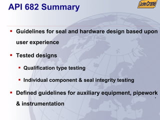


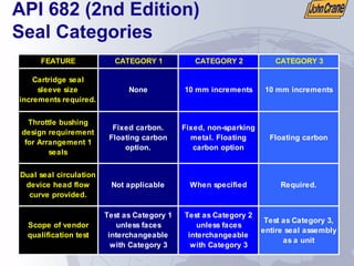
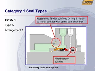

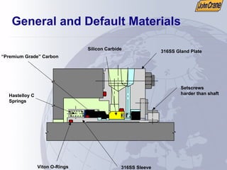


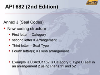
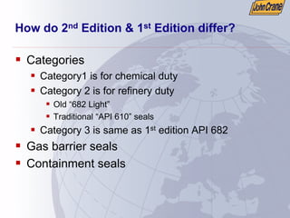
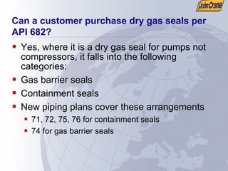
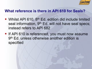
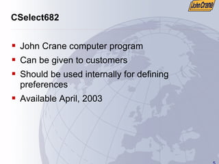
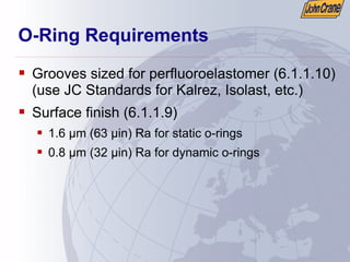
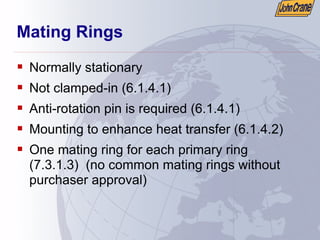
![Set Screws for Drive Collar
ƒ Maximum of eight (6.1.3.12)
ƒ Harder than shaft (6.1.3.11)
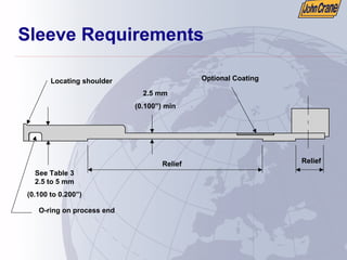
ƒ Spot drilling the shaft is acceptable but not
recommended
ƒ Can use split ring instead of drive collar for
thrust (6.1.3.13)
ƒ Set screws shall not pass through sleeve unless
sleeve bore is relieved [to avoid damage during
removal] (6.1.3.10)](https://image.slidesharecdn.com/dokumen-231023005530-a3ea1146/85/dokumen-tips_api-682-presentation-pdf-69-320.jpg)

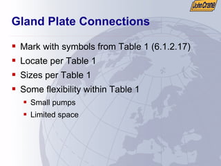
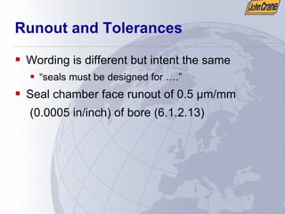
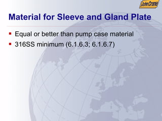

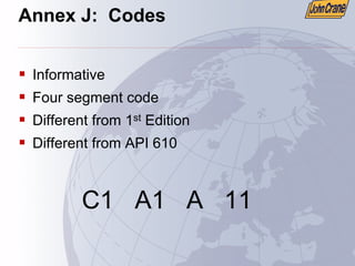
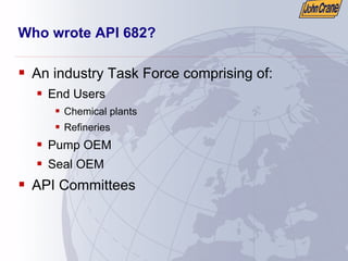
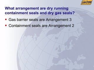
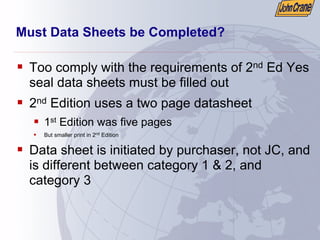
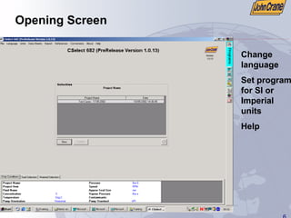
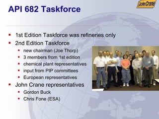
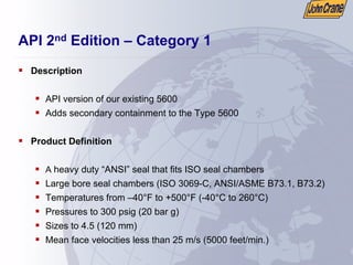
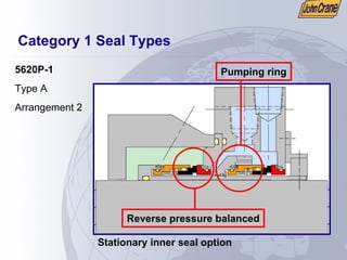
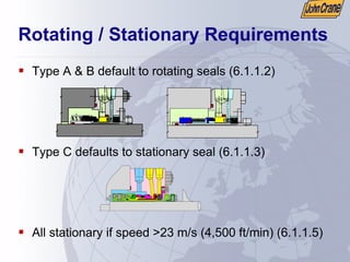
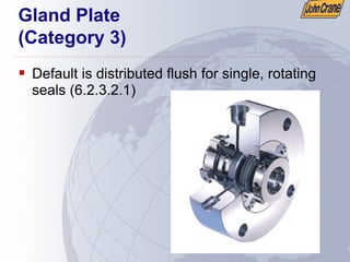
![Gland Plate
(Category 1)
ƒ Default is single point injection
ƒ Distributed flush is optional (6.2.1.2.1; 6.1.2.14)
ƒ 6.1.2.14 states “Seal chamber pressure shall not
be less than a 30% margin to maximum VP or a
20 C (36 F) product temperature margin at
maximum process temperature”
ƒ Remember
ƒ Register fit
ƒ Bolt holes, not slots
ƒ Confined gasket with metal-to-metal contact [gland to
pump] (6.2.1.2.2)](https://image.slidesharecdn.com/dokumen-231023005530-a3ea1146/85/dokumen-tips_api-682-presentation-pdf-91-320.jpg)


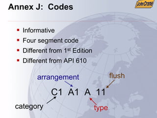
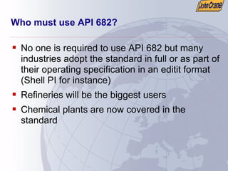
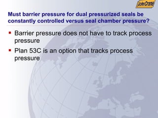
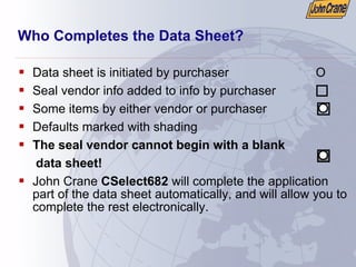
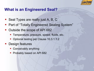
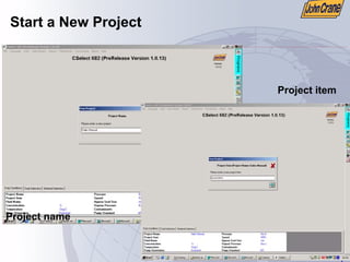
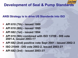
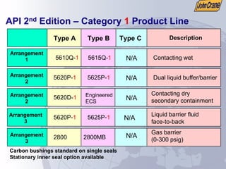
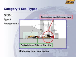
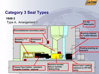
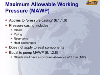
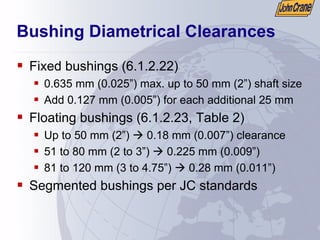
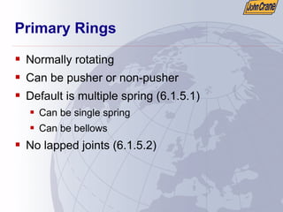
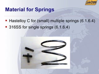
![Throttle Bushings
(Arrangement 1)
ƒ Throttle bushing required (7.1.2.1)
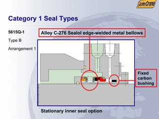
ƒ Category 1 uses fixed, carbon bushing
ƒ Category 2 uses fixed, non-sparking metal
bushing
ƒ Category 3 uses floating, carbon bushing
ƒ Category 1 & 2 can be specified [by customer] to
be a floating bushing (7.1.2.2)](https://image.slidesharecdn.com/dokumen-231023005530-a3ea1146/85/dokumen-tips_api-682-presentation-pdf-102-320.jpg)