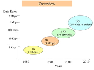
1G
(<1Kbps)
1 Kbps
10 Kbps
100Kbps
2 Mbps
1 Mbps
Data Rates
1980 1990 2000 2010
2G
(9.6Kbps)
2.5G
(10-150Kbps)
3G
(144Kbps to 2Mbps)
Years
Overview
3.
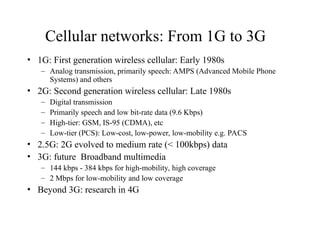
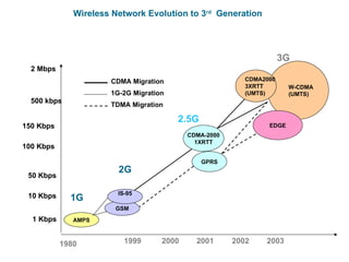
Cellular networks: From1G to 3G
• 1G: First generation wireless cellular: Early 1980s
– Analog transmission, primarily speech: AMPS (Advanced Mobile Phone
Systems) and others
• 2G: Second generation wireless cellular: Late 1980s
– Digital transmission
– Primarily speech and low bit-rate data (9.6 Kbps)
– High-tier: GSM, IS-95 (CDMA), etc
– Low-tier (PCS): Low-cost, low-power, low-mobility e.g. PACS
• 2.5G: 2G evolved to medium rate (< 100kbps) data
• 3G: future Broadband multimedia
– 144 kbps - 384 kbps for high-mobility, high coverage
– 2 Mbps for low-mobility and low coverage
• Beyond 3G: research in 4G
4.
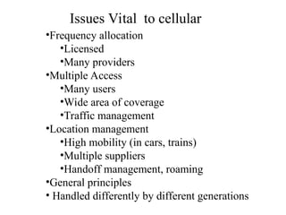
•Frequency allocation
•Licensed
•Many providers
•MultipleAccess
•Many users
•Wide area of coverage
•Traffic management
•Location management
•High mobility (in cars, trains)
•Multiple suppliers
•Handoff management, roaming
•General principles
• Handled differently by different generations
Issues Vital to cellular
5.
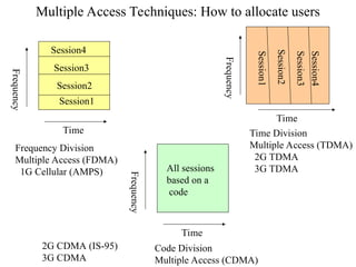
Multiple Access Techniques:How to allocate users
Time
Frequency
Session1
Session2
Session3
Session4
Frequency Division
Multiple Access (FDMA)
1G Cellular (AMPS)
Time
Frequency
Time Division
Multiple Access (TDMA)
2G TDMA
3G TDMA
Session2
Session3
Session1
Session4
Time
Frequency
Code Division
Multiple Access (CDMA)
All sessions
based on a
code
2G CDMA (IS-95)
3G CDMA
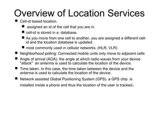
Overview of LocationServices
Cell-id based location.
assigned an id of the cell that you are in.
cell-id is stored in a database.
As you move from one cell to another, you are assigned a different cell-
id and the location database is updated.
most commonly used in cellular networks. (HLR, VLR)
Neighborhood polling: Connected mobile units only move to adjacent cells
Angle of arrival (AOA). the angle at which radio waves from your device
"attack" an antenna is used to calculate the location of the device.
Time taken. In this case, the time taken between the device and the
antenna is used to calculate the location of the device.
Network assisted Global Positioning System (GPS). a GPS chip is
installed inside a phone and thus the location of the user is tracked.
8.
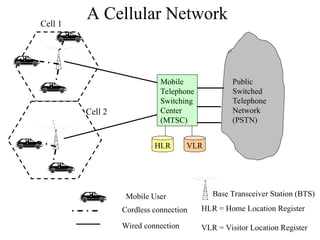
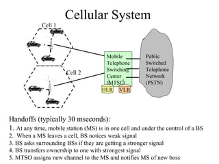
Cellular System
Handoffs (typically30 mseconds):
1. At any time, mobile station (MS) is in one cell and under the control of a BS
2. When a MS leaves a cell, BS notices weak signal
3. BS asks surrounding BSs if they are getting a stronger signal
4. BS transfers ownership to one with strongest signal
5. MTSO assigns new channel to the MS and notifies MS of new boss
Public
Switched
Telephone
Network
(PSTN)
Mobile
Telephone
Switching
Center
(MTSC)
Cell 1
Cell 2
HLR VLR
9.
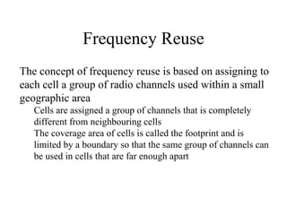
Frequency Reuse
The conceptof frequency reuse is based on assigning to
each cell a group of radio channels used within a small
geographic area
Cells are assigned a group of channels that is completely
different from neighbouring cells
The coverage area of cells is called the footprint and is
limited by a boundary so that the same group of channels can
be used in cells that are far enough apart
10.
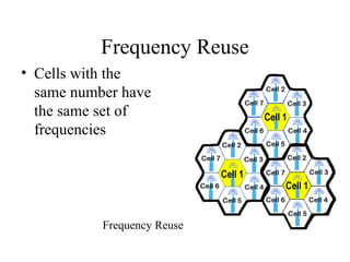
Frequency Reuse
• Cellswith the
same number have
the same set of
frequencies
Frequency Reuse
11.
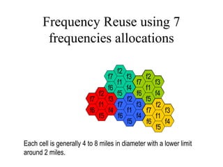
Frequency Reuse using7
frequencies allocations
f4
f3
f2
f1
f6
f7
f5 f4
f3
f2
f1
f6
f7
f5
f4
f3
f2
f1
f6
f7
f5
f4
f3
f2
f1
f6
f7
f5
f4
f3
f2
f1
f6
f7
f5
Each cell is generally 4 to 8 miles in diameter with a lower limit
around 2 miles.
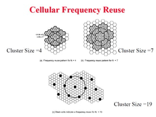
13.
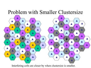
Problem with SmallerClustersize
Interfering cells are closer by when clustersize is smaller.
16.
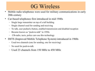
0G Wireless
• Mobileradio telephones were used for military communications in early
20th century
• Car-based telephones first introduced in mid 1940s
– Single large transmitter on top of a tall building
– Single channel used for sending and receiving
– To talk, user pushed a button, enabled transmission and disabled reception
– Became known as “push-to-talk” in 1950s
– CB-radio, taxis, police cars use this technology
• IMTS (Improved Mobile Telephone System) introduced in 1960s
– Used two channels (one for sending, one for receiving)
– No need for push-to-talk
– Used 23 channels from 150 MHz to 450 MHz
17.
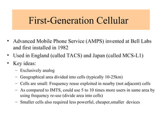
First-Generation Cellular
• AdvancedMobile Phone Service (AMPS) invented at Bell Labs
and first installed in 1982
• Used in England (called TACS) and Japan (called MCS-L1)
• Key ideas:
– Exclusively analog
– Geographical area divided into cells (typically 10-25km)
– Cells are small: Frequency reuse exploited in nearby (not adjacent) cells
– As compared to IMTS, could use 5 to 10 times more users in same area by
using frequency re-use (divide area into cells)
– Smaller cells also required less powerful, cheaper,smaller devices
19.
E
A
D
F
G C
B
E
A
D
F
G C
B
E
A
D
F
GC
B
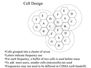
Cell Design
•Cells grouped into a cluster of seven
•Letters indicate frequency use
•For each frequency, a buffer of two cells is used before reuse
•To add more users, smaller cells (microcells) are used
•Frequencies may not need to be different in CDMA (soft handoff)
20.
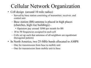
Cellular Network Organization
•Cell design (around 10 mile radius)
– Served by base station consisting of transmitter, receiver, and
control unit
– Base station (BS) antenna is placed in high places
(churches, high rise buildings) -
• Operators pay around $500 per month for BS
– 10 to 50 frequencies assigned to each cell
– Cells set up such that antennas of all neighbors are equidistant
(hexagonal pattern)
• In North America, two 25-MHz bands allocated to AMPS
– One for transmission from base to mobile unit
– One for transmission from mobile unit to base
21.
Approaches to IncreaseCapacity
• Adding/reassigning channels - some channels
are not used
• Frequency borrowing – frequencies are taken
from adjacent cells by congested cells
• Cell splitting – cells in areas of high usage
can be split into smaller cells
• Microcells – antennas move to buildings,
hills, and lamp posts
22.
Security Issues with1G
• Analog cellular phones are insecure
• Anyone with an all band radio receiver can listen in (many
scandals)
• Theft of airtime:
– all band radio receiver connected to a computer
– can record 32 bit serial number and phone number of
subscribers when calling
– can collect a large database by driving around
– Thieves go into business - reprogram stolen phones and
resell them
23.
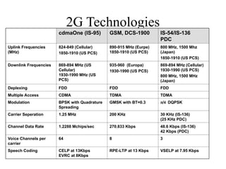
Second Generation Cellular
•Based on digital transmission
• Different approaches in US and Europe
• US: divergence
– Only one player (AMPS) in 1G
– Became several players in 2G due to competition
– Survivors
• IS-54 and IS-135: backward compatible with AMPS frequency allocation (dual mode
- analog and digital)
• IS-95: uses spread spectrum
• Europe: Convergence
– 5 incompatible 1G systems (no clear winner)
– European PTT development of GSM (uses new frequency and completely
digital communication)
28.
Advantages of Digital
Communicationsfor Wireless
• Voice, data and fax can be integrated into a
single system
• Better compression can lead to better
channel utilization
• Error correction codes can be used for
better quality
• Sophisticated encryption can be used
29.
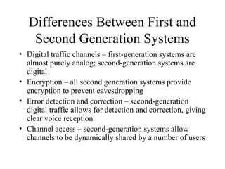
Differences Between Firstand
Second Generation Systems
• Digital traffic channels – first-generation systems are
almost purely analog; second-generation systems are
digital
• Encryption – all second generation systems provide
encryption to prevent eavesdropping
• Error detection and correction – second-generation
digital traffic allows for detection and correction, giving
clear voice reception
• Channel access – second-generation systems allow
channels to be dynamically shared by a number of users
30.
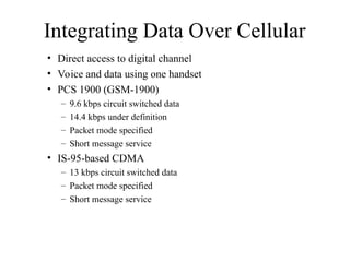
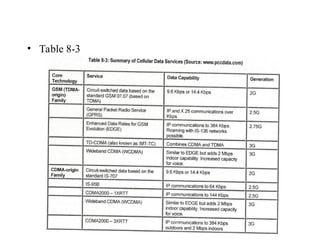
Integrating Data OverCellular
• Direct access to digital channel
• Voice and data using one handset
• PCS 1900 (GSM-1900)
– 9.6 kbps circuit switched data
– 14.4 kbps under definition
– Packet mode specified
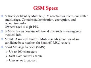
– Short message service
• IS-95-based CDMA
– 13 kbps circuit switched data
– Packet mode specified
– Short message service
31.
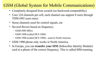
GSM (Global Systemfor Mobile Communications)
• Completely designed from scratch (no backward compatability)
• Uses 124 channels per cell, each channel can support 8 users through
TDM (992 users max)
• Some channels used for control signals, etc
• Several flavors based on frequency:
– GSM (900 MHz)
– GSM 1800 (called DCS 1800)
– GSM 1900 (called DCS 1900) - used in North America
• GSM 1900 phone only works in North America.
• In Europe, you can transfer your SIM (Subscriber Identity Module)
card to a phone of the correct frequency. This is called SIM-roaming.
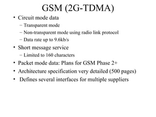
38.
GSM (2G-TDMA)
• Circuitmode data
– Transparent mode
– Non-transparent mode using radio link protocol
– Data rate up to 9.6kb/s
• Short message service
– Limited to 160 characters
• Packet mode data: Plans for GSM Phase 2+
• Architecture specification very detailed (500 pages)
• Defines several interfaces for multiple suppliers
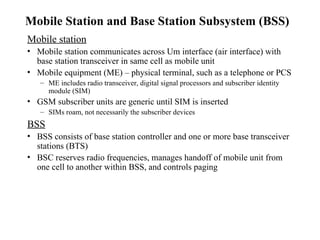
40.
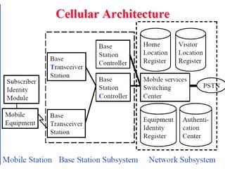
Mobile Station andBase Station Subsystem (BSS)
Mobile station
• Mobile station communicates across Um interface (air interface) with
base station transceiver in same cell as mobile unit
• Mobile equipment (ME) – physical terminal, such as a telephone or PCS
– ME includes radio transceiver, digital signal processors and subscriber identity
module (SIM)
• GSM subscriber units are generic until SIM is inserted
– SIMs roam, not necessarily the subscriber devices
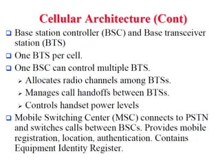
BSS
• BSS consists of base station controller and one or more base transceiver
stations (BTS)
• BSC reserves radio frequencies, manages handoff of mobile unit from
one cell to another within BSS, and controls paging
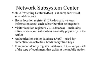
41.
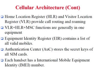
Network Subsystem Center
MobileSwitching Center (MSC) is at core; consists of
several databases
• Home location register (HLR) database – stores
information about each subscriber that belongs to it
• Visitor location register (VLR) database – maintains
information about subscribers currently physically in the
region
• Authentication center database (AuC) – used for
authentication activities, holds encryption keys
• Equipment identity register database (EIR) – keeps track
of the type of equipment that exists at the mobile station
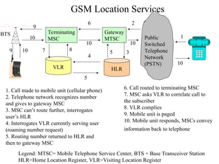
42.
GSM Location Services
Public
Switched
Telephone
Network
(PSTN)
Gateway
MTSC
VLRHLR
Terminating
MSC 1
1. Call made to mobile unit (cellular phone)
2. Telephone network recognizes number
and gives to gateway MSC
3. MSC can’t route further, interrogates
user’s HLR
4. Interrogates VLR currently serving user
(roaming number request)
5. Routing number returned to HLR and
then to gateway MSC
2
3
4
5
5
6
6. Call routed to terminating MSC
7. MSC asks VLR to correlate call to
the subscriber
8. VLR complies
9. Mobile unit is paged
10. Mobile unit responds, MSCs convey
information back to telephone
7 8
9
BTS
9 10
10
10 10
10
Legend: MTSC= Mobile Telephone Service Center, BTS = Base Transceiver Station
HLR=Home Location Register, VLR=Visiting Location Register
43.
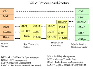
GSM Protocol Architecture
BSSMAP= BSS Mobile Application part
BTSM = BTS management
CM = Connection Management
LAPD = Link Access Protocol, D Channel
Base Transceiver
Station
Mobile
Station
Radio
LAPDm
RRM
Radio
LAPDm
RRM
MM
CM
64 Kbps
LAPD
BTSM
64 Kbps
MTP
SCCP
Base Station
Controller
64 Kbps
LAPD
BTSM
BSSMAP
64Kbps
MTP
SCCP
MM
CM
BSSMAP
Mobile Service
Switching Center
MM = Mobility Management
MTP = Message Transfer Part
RRM = Radio Resources Management
SCCP = Signal Connection Control Point
44.
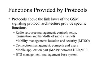
Functions Provided byProtocols
• Protocols above the link layer of the GSM
signaling protocol architecture provide specific
functions:
– Radio resource management: controls setup,
termination and handoffs of radio channels
– Mobility management: location and security (MTSO)
– Connection management: connects end users
– Mobile application part (MAP): between HLR,VLR
– BTS management: management base system
45.
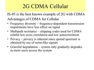
2G CDMA Cellular
IS-95is the best known example of 2G with CDMA
Advantages of CDMA for Cellular
• Frequency diversity – frequency-dependent transmission
impairments have less effect on signal
• Multipath resistance – chipping codes used for CDMA
exhibit low cross correlation and low autocorrelation
• Privacy – privacy is inherent since spread spectrum is
obtained by use of noise-like signals
• Graceful degradation – system only gradually degrades
as more users access the system
46.
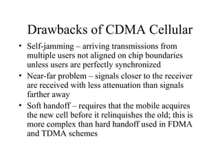
Drawbacks of CDMACellular
• Self-jamming – arriving transmissions from
multiple users not aligned on chip boundaries
unless users are perfectly synchronized
• Near-far problem – signals closer to the receiver
are received with less attenuation than signals
farther away
• Soft handoff – requires that the mobile acquires
the new cell before it relinquishes the old; this is
more complex than hard handoff used in FDMA
and TDMA schemes
47.
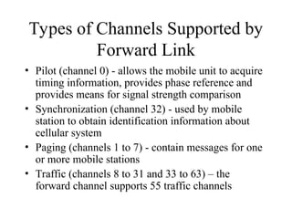
Types of ChannelsSupported by
Forward Link
• Pilot (channel 0) - allows the mobile unit to acquire
timing information, provides phase reference and
provides means for signal strength comparison
• Synchronization (channel 32) - used by mobile
station to obtain identification information about
cellular system
• Paging (channels 1 to 7) - contain messages for one
or more mobile stations
• Traffic (channels 8 to 31 and 33 to 63) – the
forward channel supports 55 traffic channels
48.
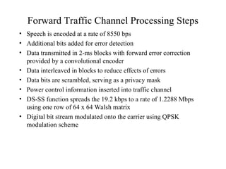
Forward Traffic ChannelProcessing Steps
• Speech is encoded at a rate of 8550 bps
• Additional bits added for error detection
• Data transmitted in 2-ms blocks with forward error correction
provided by a convolutional encoder
• Data interleaved in blocks to reduce effects of errors
• Data bits are scrambled, serving as a privacy mask
• Power control information inserted into traffic channel
• DS-SS function spreads the 19.2 kbps to a rate of 1.2288 Mbps
using one row of 64 x 64 Walsh matrix
• Digital bit stream modulated onto the carrier using QPSK
modulation scheme
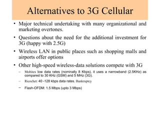
Alternatives to 3GCellular
• Major technical undertaking with many organizational and
marketing overtones.
• Questions about the need for the additional investment for
3G (happy with 2.5G)
• Wireless LAN in public places such as shopping malls and
airports offer options
• Other high-speed wireless-data solutions compete with 3G
– Mobitex low data rates (nominally 8 Kbps), it uses a narrowband (2.5KHz) as
compared to 30 KHz (GSM) and 5 MHz (3G).
– Ricochet: 40 -128 kbps data rates. Bankruptcy
– Flash-OFDM: 1.5 Mbps (upto 3 Mbps)
54.
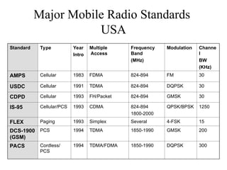
Major Mobile RadioStandards
USA
Standard Type Year
Intro
Multiple
Access
Frequency
Band
(MHz)
Modulation Channe
l
BW
(KHz)
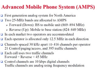
AMPS Cellular 1983 FDMA 824-894 FM 30
USDC Cellular 1991 TDMA 824-894 DQPSK 30
CDPD Cellular 1993 FH/Packet 824-894 GMSK 30
IS-95 Cellular/PCS 1993 CDMA 824-894
1800-2000
QPSK/BPSK 1250
FLEX Paging 1993 Simplex Several 4-FSK 15
DCS-1900
(GSM)
PCS 1994 TDMA 1850-1990 GMSK 200
PACS Cordless/
PCS
1994 TDMA/FDMA 1850-1990 DQPSK 300
55.
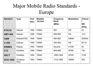
Major Mobile RadioStandards -
Europe
Standard Type Year
Intro
Multiple
Access
Frequency
Band
(MHz)
Modulation Channe
l
BW
(KHz)
ETACS Cellular 1985 FDMA 900 FM 25
NMT-900 Cellular 1986 FDMA 890-960 FM 12.5
GSM Cellular/PCS 1990 TDMA 890-960 GMSK 200KHz
C-450 Cellular 1985 FDMA 450-465 FM 20-10
ERMES Paging 1993 FDMA4 Several 4-FSK 25
CT2 Cordless 1989 FDMA 864-868 GFSK 100
DECT Cordless 1993 TDMA 1880-1900 GFSK 1728
DCS-1800 Cordless/
PCS
1993 TDMA 1710-1880 GMSK 200
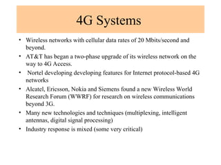
4G Systems
• Wirelessnetworks with cellular data rates of 20 Mbits/second and
beyond.
• AT&T has began a two-phase upgrade of its wireless network on the
way to 4G Access.
• Nortel developing developing features for Internet protocol-based 4G
networks
• Alcatel, Ericsson, Nokia and Siemens found a new Wireless World
Research Forum (WWRF) for research on wireless communications
beyond 3G.
• Many new technologies and techniques (multiplexing, intelligent
antennas, digital signal processing)
• Industry response is mixed (some very critical)
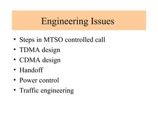
Steps in anMTSO Controlled
Call between Mobile Users
• Mobile unit initialization
• Mobile-originated call
• Paging
• Call accepted
• Ongoing call
• Handoff
• Call blocking
• Call termination
• Call drop
• Calls to/from fixed and remote mobile subscriber
60.
Mobile Wireless TDMADesign
Considerations
• Number of logical channels (number of time slots
in TDMA frame): 8
• Maximum cell radius (R): 35 km
• Frequency: region around 900 MHz
• Maximum vehicle speed (Vm):250 km/hr
• Maximum coding delay: approx. 20 ms
• Maximum delay spread (m): 10 s
• Bandwidth: Not to exceed 200 kHz (25 kHz per
channel)
61.
Mobile Wireless CDMADesign
Considerations
• Soft Handoff – mobile station temporarily
connected to more than one base station
simultaneously
• RAKE receiver – when multiple versions of a
signal arrive more than one chip interval apart,
RAKE receiver attempts to recover signals from
multiple paths and combine them
– This method achieves better performance than simply
recovering dominant signal and treating remaining
signals as noise
62.
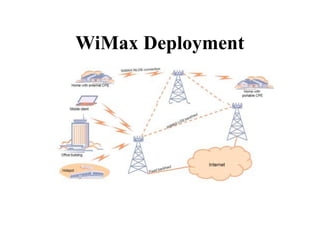
What is WiMax?
•Worldwide Interoperability for
Microwave Access
• Last mile wireless broadband access
• Alternative to cable and DSL
• Deliver data, voice, video
• Support hundreds to thousands of
homes/business
63.
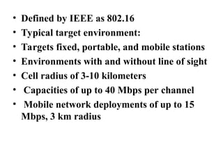
• Defined byIEEE as 802.16
• Typical target environment:
• Targets fixed, portable, and mobile stations
• Environments with and without line of sight
• Cell radius of 3-10 kilometers
• Capacities of up to 40 Mbps per channel
• Mobile network deployments of up to 15
Mbps, 3 km radius
64.
Builds on and
ExtendsWiFi Technology
• Advantages of WiFi are:
• Easy to deploy, unlicensed spectrum, low
cost
• Supports (limited) mobility
• But WiMax needs to address the
following:
65.
WiFi limitations
• Susceptibleto interference
• 802.11 targets short-range indoor operation
(mostly)
• Security is a concern
• Limited level of mobility
• WiMax is intended to complement WiFi
• WiMax Forum: promotes WiMax and looks
after interoperability