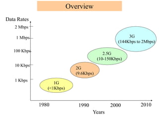
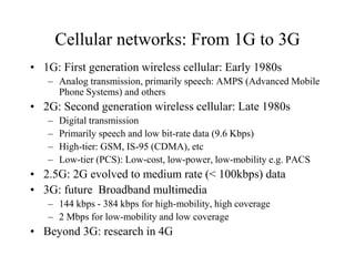
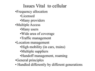
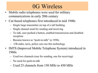
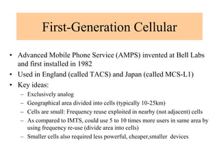
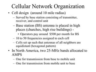
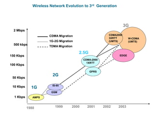
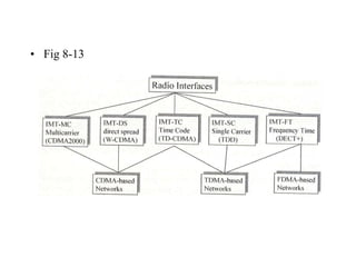
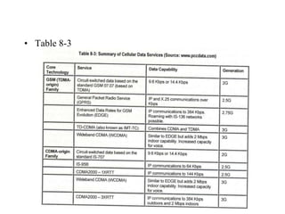
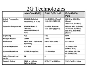
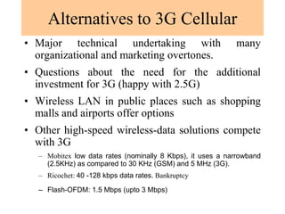
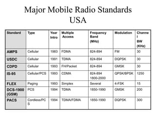
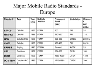
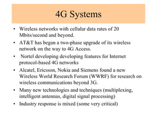
Cellular networks have evolved from 1G to 3G over several decades. 1G networks in the 1980s used analog transmission for voice only. 2G networks in the late 1980s introduced digital transmission and supported low-speed data and text messaging. Network speeds and capabilities continued to increase with 2.5G and 3G networks providing multimedia support at speeds up to 2Mbps by the early 2000s. This established the foundation for today's 4G LTE networks.
2.Cellular Networks_The final stage of connectivity is achieved by segmenting...JeyaPerumal1
A cellular network, frequently referred to as a mobile network, is a type of communication system that enables wireless communication between mobile devices. The final stage of connectivity is achieved by segmenting the comprehensive service area into several compact zones, each called a cell.
• There are many types of cellular services; before delving into details, focus on basics (helps navigate the “acronym soup”)
• Cellular network/telephony is a radio-based technology; radio waves are electromagnetic waves that antennas propagate
• Most signals are in the 850 MHz, 900 MHz, 1800 MHz, and 1900 MHz frequency bands
History, Basic concepts of wireless communication, challenges in wireless communication, cellular communication, performance criteria, wireless communication standars, how call is made?
Transcript: Selling digital books in 2024: Insights from industry leaders - T...BookNet Canada
The publishing industry has been selling digital audiobooks and ebooks for over a decade and has found its groove. What’s changed? What has stayed the same? Where do we go from here? Join a group of leading sales peers from across the industry for a conversation about the lessons learned since the popularization of digital books, best practices, digital book supply chain management, and more.
Link to video recording: https://bnctechforum.ca/sessions/selling-digital-books-in-2024-insights-from-industry-leaders/
Presented by BookNet Canada on May 28, 2024, with support from the Department of Canadian Heritage.
JMeter webinar - integration with InfluxDB and GrafanaRTTS
Watch this recorded webinar about real-time monitoring of application performance. See how to integrate Apache JMeter, the open-source leader in performance testing, with InfluxDB, the open-source time-series database, and Grafana, the open-source analytics and visualization application.
In this webinar, we will review the benefits of leveraging InfluxDB and Grafana when executing load tests and demonstrate how these tools are used to visualize performance metrics.
Length: 30 minutes
Session Overview
-------------------------------------------
During this webinar, we will cover the following topics while demonstrating the integrations of JMeter, InfluxDB and Grafana:
- What out-of-the-box solutions are available for real-time monitoring JMeter tests?
- What are the benefits of integrating InfluxDB and Grafana into the load testing stack?
- Which features are provided by Grafana?
- Demonstration of InfluxDB and Grafana using a practice web application
To view the webinar recording, go to:
https://www.rttsweb.com/jmeter-integration-webinar
Essentials of Automations: Optimizing FME Workflows with ParametersSafe Software
Are you looking to streamline your workflows and boost your projects’ efficiency? Do you find yourself searching for ways to add flexibility and control over your FME workflows? If so, you’re in the right place.
Join us for an insightful dive into the world of FME parameters, a critical element in optimizing workflow efficiency. This webinar marks the beginning of our three-part “Essentials of Automation” series. This first webinar is designed to equip you with the knowledge and skills to utilize parameters effectively: enhancing the flexibility, maintainability, and user control of your FME projects.
Here’s what you’ll gain:
- Essentials of FME Parameters: Understand the pivotal role of parameters, including Reader/Writer, Transformer, User, and FME Flow categories. Discover how they are the key to unlocking automation and optimization within your workflows.
- Practical Applications in FME Form: Delve into key user parameter types including choice, connections, and file URLs. Allow users to control how a workflow runs, making your workflows more reusable. Learn to import values and deliver the best user experience for your workflows while enhancing accuracy.
- Optimization Strategies in FME Flow: Explore the creation and strategic deployment of parameters in FME Flow, including the use of deployment and geometry parameters, to maximize workflow efficiency.
- Pro Tips for Success: Gain insights on parameterizing connections and leveraging new features like Conditional Visibility for clarity and simplicity.
We’ll wrap up with a glimpse into future webinars, followed by a Q&A session to address your specific questions surrounding this topic.
Don’t miss this opportunity to elevate your FME expertise and drive your projects to new heights of efficiency.
Dev Dives: Train smarter, not harder – active learning and UiPath LLMs for do...UiPathCommunity
💥 Speed, accuracy, and scaling – discover the superpowers of GenAI in action with UiPath Document Understanding and Communications Mining™:
See how to accelerate model training and optimize model performance with active learning
Learn about the latest enhancements to out-of-the-box document processing – with little to no training required
Get an exclusive demo of the new family of UiPath LLMs – GenAI models specialized for processing different types of documents and messages
This is a hands-on session specifically designed for automation developers and AI enthusiasts seeking to enhance their knowledge in leveraging the latest intelligent document processing capabilities offered by UiPath.
Speakers:
👨🏫 Andras Palfi, Senior Product Manager, UiPath
👩🏫 Lenka Dulovicova, Product Program Manager, UiPath
Software Delivery At the Speed of AI: Inflectra Invests In AI-Powered QualityInflectra
In this insightful webinar, Inflectra explores how artificial intelligence (AI) is transforming software development and testing. Discover how AI-powered tools are revolutionizing every stage of the software development lifecycle (SDLC), from design and prototyping to testing, deployment, and monitoring.
Learn about:
• The Future of Testing: How AI is shifting testing towards verification, analysis, and higher-level skills, while reducing repetitive tasks.
• Test Automation: How AI-powered test case generation, optimization, and self-healing tests are making testing more efficient and effective.
• Visual Testing: Explore the emerging capabilities of AI in visual testing and how it's set to revolutionize UI verification.
• Inflectra's AI Solutions: See demonstrations of Inflectra's cutting-edge AI tools like the ChatGPT plugin and Azure Open AI platform, designed to streamline your testing process.
Whether you're a developer, tester, or QA professional, this webinar will give you valuable insights into how AI is shaping the future of software delivery.
Accelerate your Kubernetes clusters with Varnish CachingThijs Feryn
A presentation about the usage and availability of Varnish on Kubernetes. This talk explores the capabilities of Varnish caching and shows how to use the Varnish Helm chart to deploy it to Kubernetes.
This presentation was delivered at K8SUG Singapore. See https://feryn.eu/presentations/accelerate-your-kubernetes-clusters-with-varnish-caching-k8sug-singapore-28-2024 for more details.
Neuro-symbolic is not enough, we need neuro-*semantic*Frank van Harmelen
Neuro-symbolic (NeSy) AI is on the rise. However, simply machine learning on just any symbolic structure is not sufficient to really harvest the gains of NeSy. These will only be gained when the symbolic structures have an actual semantics. I give an operational definition of semantics as “predictable inference”.
All of this illustrated with link prediction over knowledge graphs, but the argument is general.
DevOps and Testing slides at DASA ConnectKari Kakkonen
My and Rik Marselis slides at 30.5.2024 DASA Connect conference. We discuss about what is testing, then what is agile testing and finally what is Testing in DevOps. Finally we had lovely workshop with the participants trying to find out different ways to think about quality and testing in different parts of the DevOps infinity loop.
Let's dive deeper into the world of ODC! Ricardo Alves (OutSystems) will join us to tell all about the new Data Fabric. After that, Sezen de Bruijn (OutSystems) will get into the details on how to best design a sturdy architecture within ODC.
Search and Society: Reimagining Information Access for Radical FuturesBhaskar Mitra
The field of Information retrieval (IR) is currently undergoing a transformative shift, at least partly due to the emerging applications of generative AI to information access. In this talk, we will deliberate on the sociotechnical implications of generative AI for information access. We will argue that there is both a critical necessity and an exciting opportunity for the IR community to re-center our research agendas on societal needs while dismantling the artificial separation between the work on fairness, accountability, transparency, and ethics in IR and the rest of IR research. Instead of adopting a reactionary strategy of trying to mitigate potential social harms from emerging technologies, the community should aim to proactively set the research agenda for the kinds of systems we should build inspired by diverse explicitly stated sociotechnical imaginaries. The sociotechnical imaginaries that underpin the design and development of information access technologies needs to be explicitly articulated, and we need to develop theories of change in context of these diverse perspectives. Our guiding future imaginaries must be informed by other academic fields, such as democratic theory and critical theory, and should be co-developed with social science scholars, legal scholars, civil rights and social justice activists, and artists, among others.
Slack (or Teams) Automation for Bonterra Impact Management (fka Social Soluti...Jeffrey Haguewood
Sidekick Solutions uses Bonterra Impact Management (fka Social Solutions Apricot) and automation solutions to integrate data for business workflows.
We believe integration and automation are essential to user experience and the promise of efficient work through technology. Automation is the critical ingredient to realizing that full vision. We develop integration products and services for Bonterra Case Management software to support the deployment of automations for a variety of use cases.
This video focuses on the notifications, alerts, and approval requests using Slack for Bonterra Impact Management. The solutions covered in this webinar can also be deployed for Microsoft Teams.
Interested in deploying notification automations for Bonterra Impact Management? Contact us at sales@sidekicksolutionsllc.com to discuss next steps.
2. 1G
(<1Kbps)
1 Kbps
10 Kbps
100 Kbps
2 Mbps
1 Mbps
Data Rates
1980 1990 2000 2010
2G
(9.6Kbps)
2.5G
(10-150Kbps)
3G
(144Kbps to 2Mbps)
Years
Overview
3. Cellular networks: From 1G to 3G
• 1G: First generation wireless cellular: Early 1980s
– Analog transmission, primarily speech: AMPS (Advanced Mobile
Phone Systems) and others
• 2G: Second generation wireless cellular: Late 1980s
– Digital transmission
– Primarily speech and low bit-rate data (9.6 Kbps)
– High-tier: GSM, IS-95 (CDMA), etc
– Low-tier (PCS): Low-cost, low-power, low-mobility e.g. PACS
• 2.5G: 2G evolved to medium rate (< 100kbps) data
• 3G: future Broadband multimedia
– 144 kbps - 384 kbps for high-mobility, high coverage
– 2 Mbps for low-mobility and low coverage
• Beyond 3G: research in 4G
4. •Frequency allocation
•Licensed
•Many providers
•Multiple Access
•Many users
•Wide area of coverage
•Traffic management
•Location management
•High mobility (in cars, trains)
•Multiple suppliers
•Handoff management, roaming
•General principles
• Handled differently by different generations
Issues Vital to cellular
5. Multiple Access Techniques: How to allocate users
Time
Frequency
Session1
Session2
Session3
Session4
Frequency Division
Multiple Access (FDMA)
1G Cellular (AMPS)
Time
Frequency
Time Division
Multiple Access (TDMA)
2G TDMA
3G TDMA
Session2
Session3
Session1
Session4
Time
Frequency
Code Division
Multiple Access (CDMA)
All sessions
based on a
code
2G CDMA (IS-95)
3G CDMA
7. Overview of Location Services
Cell-id based location.
assigned an id of the cell that you are in.
cell-id is stored in a database.
As you move from one cell to another, you are assigned a
different cell-id and the location database is updated.
most commonly used in cellular networks. (HLR, VLR)
Neighborhood polling: Connected mobile units only move to
adjacent cells
Angle of arrival (AOA). the angle at which radio waves from your
device "attack" an antenna is used to calculate the location of
the device.
Time taken. In this case, the time taken between the device and
the antenna is used to calculate the location of the device.
Network assisted Global Positioning System (GPS). a GPS chip
is installed inside a phone and thus the location of the user is
tracked.
8. Cellular System
Handoffs (typically 30 mseconds):
1. At any time, mobile station (MS) is in one cell and under the control of a BS
2. When a MS leaves a cell, BS notices weak signal
3. BS asks surrounding BSs if they are getting a stronger signal
4. BS transfers ownership to one with strongest signal
5. MTSO assigns new channel to the MS and notifies MS of new boss
Public
Switched
Telephone
Network
(PSTN)
Mobile
Telephone
Switching
Center
(MTSC)
Cell 1
Cell 2
HLR VLR
9. Frequency Reuse
The concept of frequency reuse is based on assigning to
each cell a group of radio channels used within a small
geographic area
Cells are assigned a group of channels that is completely
different from neighbouring cells
The coverage area of cells is called the footprint and is
limited by a boundary so that the same group of channels can
be used in cells that are far enough apart
10. Frequency Reuse
• Cells with the
same number have
the same set of
frequencies
Frequency Reuse
11. Frequency Reuse using 7
frequencies allocations
f4
f3
f2
f1
f6
f7
f5 f4
f3
f2
f1
f6
f7
f5
f4
f3
f2
f1
f6
f7
f5
f4
f3
f2
f1
f6
f7
f5
f4
f3
f2
f1
f6
f7
f5
Each cell is generally 4 to 8 miles in diameter with a lower limit
around 2 miles.
12.
13. Problem with Smaller Clustersize
Interfering cells are closer by when clustersize is smaller.
14.
15.
16. 0G Wireless
• Mobile radio telephones were used for military
communications in early 20th century
• Car-based telephones first introduced in mid 1940s
– Single large transmitter on top of a tall building
– Single channel used for sending and receiving
– To talk, user pushed a button, enabled transmission and disabled
reception
– Became known as “push-to-talk” in 1950s
– CB-radio, taxis, police cars use this technology
• IMTS (Improved Mobile Telephone System) introduced in
1960s
– Used two channels (one for sending, one for receiving)
– No need for push-to-talk
– Used 23 channels from 150 MHz to 450 MHz
17. First-Generation Cellular
• Advanced Mobile Phone Service (AMPS) invented at Bell Labs
and first installed in 1982
• Used in England (called TACS) and Japan (called MCS-L1)
• Key ideas:
– Exclusively analog
– Geographical area divided into cells (typically 10-25km)
– Cells are small: Frequency reuse exploited in nearby (not adjacent) cells
– As compared to IMTS, could use 5 to 10 times more users in same area by
using frequency re-use (divide area into cells)
– Smaller cells also required less powerful, cheaper,smaller devices
18.
19. E
A
D
F
G C
B
E
A
D
F
G C
B
E
A
D
F
G C
B
Cell Design
•Cells grouped into a cluster of seven
•Letters indicate frequency use
•For each frequency, a buffer of two cells is used before reuse
•To add more users, smaller cells (microcells) are used
•Frequencies may not need to be different in CDMA (soft handoff)
20. Cellular Network Organization
• Cell design (around 10 mile radius)
– Served by base station consisting of transmitter,
receiver, and control unit
– Base station (BS) antenna is placed in high
places (churches, high rise buildings) -
• Operators pay around $500 per month for BS
– 10 to 50 frequencies assigned to each cell
– Cells set up such that antennas of all neighbors are
equidistant (hexagonal pattern)
• In North America, two 25-MHz bands allocated to
AMPS
– One for transmission from base to mobile unit
– One for transmission from mobile unit to base
21. Approaches to Increase Capacity
• Adding/reassigning channels - some channels
are not used
• Frequency borrowing – frequencies are taken
from adjacent cells by congested cells
• Cell splitting – cells in areas of high usage
can be split into smaller cells
• Microcells – antennas move to buildings,
hills, and lamp posts
22. Security Issues with 1G
• Analog cellular phones are insecure
• Anyone with an all band radio receiver can listen in
(many scandals)
• Theft of airtime:
– all band radio receiver connected to a computer
– can record 32 bit serial number and phone number
of subscribers when calling
– can collect a large database by driving around
– Thieves go into business - reprogram stolen
phones and resell them
23. Second Generation Cellular
• Based on digital transmission
• Different approaches in US and Europe
• US: divergence
– Only one player (AMPS) in 1G
– Became several players in 2G due to competition
– Survivors
• IS-54 and IS-135: backward compatible with AMPS frequency
allocation (dual mode - analog and digital)
• IS-95: uses spread spectrum
• Europe: Convergence
– 5 incompatible 1G systems (no clear winner)
– European PTT development of GSM (uses new
frequency and completely digital communication)
24.
25.
26.
27.
28. Advantages of Digital
Communications for Wireless
• Voice, data and fax can be integrated into a
single system
• Better compression can lead to better
channel utilization
• Error correction codes can be used for better
quality
• Sophisticated encryption can be used
29. Differences Between First and
Second Generation Systems
• Digital traffic channels – first-generation systems
are almost purely analog; second-generation
systems are digital
• Encryption – all second generation systems
provide encryption to prevent eavesdropping
• Error detection and correction – second-generation
digital traffic allows for detection and correction,
giving clear voice reception
• Channel access – second-generation systems allow
channels to be dynamically shared by a number of
users
30. Integrating Data Over Cellular
• Direct access to digital channel
• Voice and data using one handset
• PCS 1900 (GSM-1900)
– 9.6 kbps circuit switched data
– 14.4 kbps under definition
– Packet mode specified
– Short message service
• IS-95-based CDMA
– 13 kbps circuit switched data
– Packet mode specified
– Short message service
31. GSM (Global System for Mobile Communications)
• Completely designed from scratch (no backward
compatability)
• Uses 124 channels per cell, each channel can
support 8 users through TDM (992 users max)
• Some channels used for control signals, etc
• Several flavors based on frequency:
– GSM (900 MHz)
– GSM 1800 (called DCS 1800)
– GSM 1900 (called DCS 1900) - used in North America
• GSM 1900 phone only works in North America.
• In Europe, you can transfer your SIM (Subscriber
Identity Module) card to a phone of the correct
frequency. This is called SIM-roaming.
32.
33.
34.
35.
36.
37.
38. GSM (2G-TDMA)
• Circuit mode data
– Transparent mode
– Non-transparent mode using radio link protocol
– Data rate up to 9.6kb/s
• Short message service
– Limited to 160 characters
• Packet mode data: Plans for GSM Phase 2+
• Architecture specification very detailed
(500 pages)
• Defines several interfaces for multiple
suppliers
39.
40. Mobile Station and Base Station Subsystem (BSS)
Mobile station
• Mobile station communicates across Um interface (air
interface) with base station transceiver in same cell as
mobile unit
• Mobile equipment (ME) – physical terminal, such as a
telephone or PCS
– ME includes radio transceiver, digital signal processors and
subscriber identity module (SIM)
• GSM subscriber units are generic until SIM is inserted
– SIMs roam, not necessarily the subscriber devices
BSS
• BSS consists of base station controller and one or more
base transceiver stations (BTS)
• BSC reserves radio frequencies, manages handoff of
mobile unit from one cell to another within BSS, and
controls paging
41. Network Subsystem Center
Mobile Switching Center (MSC) is at core; consists
of several databases
• Home location register (HLR) database – stores
information about each subscriber that belongs to
it
• Visitor location register (VLR) database –
maintains information about subscribers currently
physically in the region
• Authentication center database (AuC) – used for
authentication activities, holds encryption keys
• Equipment identity register database (EIR) –
keeps track of the type of equipment that exists at
the mobile station
42. GSM Location Services
Public
Switched
Telephone
Network
(PSTN)
Gateway
MTSC
VLR HLR
Terminating
MSC 1
1. Call made to mobile unit (cellular phone)
2. Telephone network recognizes number
and gives to gateway MSC
3. MSC can’t route further, interrogates
user’s HLR
4. Interrogates VLR currently serving user
(roaming number request)
5. Routing number returned to HLR and
then to gateway MSC
2
3
4
5
5
6
6. Call routed to terminating MSC
7. MSC asks VLR to correlate call to
the subscriber
8. VLR complies
9. Mobile unit is paged
10. Mobile unit responds, MSCs convey
information back to telephone
7 8
9
BTS
9 10
10
10 10
10
Legend: MTSC= Mobile Telephone Service Center, BTS = Base Transceiver Station
HLR=Home Location Register, VLR=Visiting Location Register
43. GSM Protocol Architecture
BSSMAP = BSS Mobile Application part
BTSM = BTS management
CM = Connection Management
LAPD = Link Access Protocol, D Channel
Base Transceiver
Station
Mobile
Station
Radio
LAPDm
RRM
Radio
LAPDm
RRM
MM
CM
64 Kbps
LAPD
BTSM
64 Kbps
MTP
SCCP
Base Station
Controller
64 Kbps
LAPD
BTSM
BSSMAP
64Kbps
MTP
SCCP
MM
CM
BSSMAP
Mobile Service
Switching Center
MM = Mobility Management
MTP = Message Transfer Part
RRM = Radio Resources Management
SCCP = Signal Connection Control Point
44. Functions Provided by Protocols
• Protocols above the link layer of the GSM
signaling protocol architecture provide
specific functions:
– Radio resource management: controls setup,
termination and handoffs of radio channels
– Mobility management: location and security
(MTSO)
– Connection management: connects end users
– Mobile application part (MAP): between
HLR,VLR
– BTS management: management base system
45. 2G CDMA Cellular
IS-95 is the best known example of 2G with
CDMA
Advantages of CDMA for Cellular
• Frequency diversity – frequency-dependent
transmission impairments have less effect on
signal
• Multipath resistance – chipping codes used for
CDMA exhibit low cross correlation and low
autocorrelation
• Privacy – privacy is inherent since spread
spectrum is obtained by use of noise-like signals
• Graceful degradation – system only gradually
degrades as more users access the system
46. Drawbacks of CDMA Cellular
• Self-jamming – arriving transmissions from
multiple users not aligned on chip boundaries
unless users are perfectly synchronized
• Near-far problem – signals closer to the receiver
are received with less attenuation than signals
farther away
• Soft handoff – requires that the mobile acquires
the new cell before it relinquishes the old; this is
more complex than hard handoff used in FDMA
and TDMA schemes
47. Types of Channels Supported by
Forward Link
• Pilot (channel 0) - allows the mobile unit to
acquire timing information, provides phase
reference and provides means for signal strength
comparison
• Synchronization (channel 32) - used by mobile
station to obtain identification information about
cellular system
• Paging (channels 1 to 7) - contain messages for
one or more mobile stations
• Traffic (channels 8 to 31 and 33 to 63) – the
forward channel supports 55 traffic channels
48. Forward Traffic Channel Processing Steps
• Speech is encoded at a rate of 8550 bps
• Additional bits added for error detection
• Data transmitted in 2-ms blocks with forward error
correction provided by a convolutional encoder
• Data interleaved in blocks to reduce effects of errors
• Data bits are scrambled, serving as a privacy mask
• Power control information inserted into traffic channel
• DS-SS function spreads the 19.2 kbps to a rate of 1.2288
Mbps using one row of 64 x 64 Walsh matrix
• Digital bit stream modulated onto the carrier using QPSK
modulation scheme
53. Alternatives to 3G Cellular
• Major technical undertaking with many
organizational and marketing overtones.
• Questions about the need for the additional
investment for 3G (happy with 2.5G)
• Wireless LAN in public places such as shopping
malls and airports offer options
• Other high-speed wireless-data solutions compete
with 3G
– Mobitex low data rates (nominally 8 Kbps), it uses a narrowband
(2.5KHz) as compared to 30 KHz (GSM) and 5 MHz (3G).
– Ricochet: 40 -128 kbps data rates. Bankruptcy
– Flash-OFDM: 1.5 Mbps (upto 3 Mbps)
54. Major Mobile Radio Standards
USA
Standard Type Year
Intro
Multiple
Access
Frequency
Band
(MHz)
Modulation Channe
l
BW
(KHz)
AMPS Cellular 1983 FDMA 824-894 FM 30
USDC Cellular 1991 TDMA 824-894 DQPSK 30
CDPD Cellular 1993 FH/Packet 824-894 GMSK 30
IS-95 Cellular/PCS 1993 CDMA 824-894
1800-2000
QPSK/BPSK 1250
FLEX Paging 1993 Simplex Several 4-FSK 15
DCS-1900
(GSM)
PCS 1994 TDMA 1850-1990 GMSK 200
PACS Cordless/PC
S
1994 TDMA/FDMA 1850-1990 DQPSK 300
55. Major Mobile Radio Standards -
Europe
Standard Type Year
Intro
Multiple
Access
Frequency
Band
(MHz)
Modulation Channe
l
BW
(KHz)
ETACS Cellular 1985 FDMA 900 FM 25
NMT-900 Cellular 1986 FDMA 890-960 FM 12.5
GSM Cellular/PCS 1990 TDMA 890-960 GMSK 200KHz
C-450 Cellular 1985 FDMA 450-465 FM 20-10
ERMES Paging 1993 FDMA4 Several 4-FSK 25
CT2 Cordless 1989 FDMA 864-868 GFSK 100
DECT Cordless 1993 TDMA 1880-1900 GFSK 1728
DCS-1800 Cordless/PC
S
1993 TDMA 1710-1880 GMSK 200
57. 4G Systems
• Wireless networks with cellular data rates of 20
Mbits/second and beyond.
• AT&T has began a two-phase upgrade of its wireless
network on the way to 4G Access.
• Nortel developing developing features for Internet
protocol-based 4G networks
• Alcatel, Ericsson, Nokia and Siemens found a new
Wireless World Research Forum (WWRF) for research on
wireless communications beyond 3G.
• Many new technologies and techniques (multiplexing,
intelligent antennas, digital signal processing)
• Industry response is mixed (some very critical)
58. Engineering Issues
• Steps in MTSO controlled call
• TDMA design
• CDMA design
• Handoff
• Power control
• Traffic engineering
59. Steps in an MTSO Controlled
Call between Mobile Users
• Mobile unit initialization
• Mobile-originated call
• Paging
• Call accepted
• Ongoing call
• Handoff
• Call blocking
• Call termination
• Call drop
• Calls to/from fixed and remote mobile subscriber
60. Mobile Wireless TDMA Design
Considerations
• Number of logical channels (number of time slots
in TDMA frame): 8
• Maximum cell radius (R): 35 km
• Frequency: region around 900 MHz
• Maximum vehicle speed (Vm):250 km/hr
• Maximum coding delay: approx. 20 ms
• Maximum delay spread (m): 10 s
• Bandwidth: Not to exceed 200 kHz (25 kHz per
channel)
61. Mobile Wireless CDMA Design
Considerations
• Soft Handoff – mobile station temporarily
connected to more than one base station
simultaneously
• RAKE receiver – when multiple versions of a
signal arrive more than one chip interval apart,
RAKE receiver attempts to recover signals from
multiple paths and combine them
– This method achieves better performance than simply
recovering dominant signal and treating remaining
signals as noise
62. What is WiMax?
• Worldwide Interoperability for
Microwave Access
• Last mile wireless broadband access
• Alternative to cable and DSL
• Deliver data, voice, video
• Support hundreds to thousands of
homes/business
63. • Defined by IEEE as 802.16
• Typical target environment:
• Targets fixed, portable, and mobile stations
• Environments with and without line of sight
• Cell radius of 3-10 kilometers
• Capacities of up to 40 Mbps per channel
• Mobile network deployments of up to 15
Mbps, 3 km radius
64. Builds on and
Extends WiFi Technology
• Advantages of WiFi are:
• Easy to deploy, unlicensed spectrum, low
cost
• Supports (limited) mobility
• But WiMax needs to address the
following:
65. WiFi limitations
• Susceptible to interference
• 802.11 targets short-range indoor
operation (mostly)
• Security is a concern
• Limited level of mobility
• WiMax is intended to complement WiFi
• WiMax Forum: promotes WiMax and
looks after interoperability