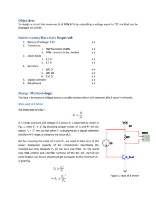
SlideShare a Scribd company logo
1 of 8
Download to read offline
EC 204: ANLOG CIRCUITS LABORATORY 
Experiment 1 
β‐meter


Manzil Zaheer 08010252
Payoj Kissan 08010823
Sachin Rajoria 08010826
 
   
To design a circuit that measures β of NPN BJTs by outputting a voltage equal to “β” mV that can be 
displayed on a DVM.  
Objective: 
To design a circuit that measures β of NPN BJTs by outputting a voltage equal to “β” mV that can be 
displayed on a DVM.  
Instruments/Materials Required: 
1. Battery of Voltage: 7.5V         x 1 
2. Transistors: 
i. PNP transistor CK100      x 1 
ii. NPN transistor to be checked     x 1 
3. Zener diode 
i. 2.7 V             x 1 
ii. 4.7 V          x 1 
4. Resistors: 
i. 100 Ω          x 4 
ii. 200 kΩ          x 2 
iii. 330 Ω          x 1 
5. Digital voltmeter          x 1 
6. Breadboard            x 1 
Design Methodology: 
The idea is to measure voltage across a suitable resistor which will represent the β value in millivolts. 
Main part of β‐Meter 
We know that for a BJT,


If IB is kept constant and voltage (Vo) across RC is observed as shown in 
Fig. 1, then      . By choosing proper values of IB and RC we can 
obtain Vo = “β” mV, so that when Vo is displayed on a digital voltmeter 
(DVM) in mV range, it indicates the value of β. 
But for choosing the value of IB and RC, we need to take care of the 
power  dissipation  capacity  of  the  components.  Specifically  the 
resistors can only dissipate   (in our case 250 mW). For  the  worst 
case  that  emitter  and  collector  terminal  of  the  BJT  are  shorted  for 
some reason, our device should not get damaged. So the minimum RC, 
is given by 
 
 
Figure 1: Idea of β‐meter
Further from this we can get, 
 
 
For displaying Vo = “β” mV we need that  1 mV, 
10 10
 
A  constant  current  source  is  required  to  make  IB immune  to  disparity  in  VBE of  the  transistors  being 
tested. Plus the constant current source should be able to drive a grounded load. We used the following 
simple transistor based current source for this purpose. 
The Constant Current Source 
The Fig. 2 shows proposed constant current source. DZ is a zener diode which, when reverse biased (as 
shown in the circuit) has a constant voltage drop across it irrespective of the current flowing through it. 
Thus, as long as the zener current (IZ) is above a certain level (IZ‐min, called holding current), the voltage 
across the zener diode (VZ) will be constant. Resistor R1 supplies the zener current and the base current 
(I’B)  of  PNP  transistor  (Q1).  The  constant  zener  voltage  is  applied  across  the  base  of  Q1  and  emitter 
resistor R2. The operation of the circuit is as follows: 
Voltage across R2 (VR2) is given by VZ + VBE, where VBE is the base‐emitter drop of Q1. The emitter current 
of Q1 which is also the current through R2 is given by 
 
Since VZ is constant and VBE is also (approximately) constant for a given temperature, it follows that VR2 is 
constant and hence I’E is also constant. Due to transistor action, emitter current I’E is very nearly equal to 
the collector current I’C of the transistor (which in turn, is the current through the load). Thus, the load 
current is constant (neglecting the output resistance of the transistor due to the Early effect) and the 
circuit operates as a constant current source. As long as the temperature remains constant (or doesn't 
vary much), the load current will be independent of the supply voltage, R1 and the transistor's gain. R2 
allows the load current to be set at any desirable value and is calculated by 
 
The resistor R1 has to be chosen keeping in mind the holding current of zener diode, 
 
 
Voltage Regulation of CCS: This circuit design is immune to voltage variation in VCC. Let the variation in 
VCC  be ∆ , then the voltage at base of the transistor Q1 is  ∆ ,  and hence at the 
emitter is  ∆   . Thus the voltage across the resistor R2 is 
∆  
  ∆ ∆    
 
Hence the variation in the source voltage does not affect the voltage across VR2 and in turn the constant 
current output, 
 
Overall Voltage Regulation 
To  obtain  further  voltage  stability,  we  add  a  zener  diode 
parallel to the whole circuit, as shown in Fig. 3. This makes 
the circuit further independent of the voltage, provided it is 
higher than the breakdown voltage of the zener diode.  
Figure 2: Design of Constant Current Source
Figure 3: Use of zener 
as voltage stabilizer 
Calculations: 
Let us choose the VBatt to be 7.5V (a standard value). Then, the other circuit parameters are as follows: 
 Effective Supply Voltage (VCC) [Across the zener diode of 4.7 V]  
4.7V 
 Collector Resistance (RC) 
4.7
0.25
88.36 Ω 
Choose  200 Ω 
 Constant Current (IB) from CCS 
10 10
200
5 10  A 5 A 
 Transistor (Q1) in the CCS: PNP transistor CK100 with 
0.7 V 
(Assumed, datasheet not available) 
 Zener Diode in CCS 
2.7 V, 5 mA 
……. 
 Resistor (R2) in CCS 
 
2.7 0.7
5 10
 
4 10  Ω 400 kΩ 
 Resistor (R1) in CCS 
4.7 2.7
5 10
400 Ω 
Choose  330 Ω 
(To allow slight variations in supply voltage) 
 
 
Circuit Diagram 
  
 
Figure 4: The complete β‐meter circuit 
VCC
Observations: 
1. Testing of the constant current source:  
 
Sr. No.  VBatt  RLoad  IB (by CSS) 
1.  5.5 V ‐ 5 µA 
2.  5.5 V 100 Ω 5 µA 
3.  7.5 V ‐ 5 µA 
4.  7.5 V 100 Ω 5.1 µA 
5.  11.5 V ‐ 5.8 µA 
 
 
2. β measured by the above designed circuit:  
 
Sr. No.  Transistor  β (DMM)  β (Circuit) 
1.  Q1 (2N2222) 161 153 
2.  Q2 (2N2222) 169 168 
 
 
Result: 
1. The β‐meter was successfully constructed using discrete components and demonstrated with 
immunity to slight variations in the supply voltage. 
2. β  of  the  given  transistor  was  found  to  be  quite  close  to  the  true  value  by  the  use  of  above 
designed circuit. 
i. β : 153 by the circuit as compared to 161 by DMM 
ii. β : 168 by the circuit as compared to 169 by DMM  


Comments: 
The  circuit’s  reliability  can  be  improved  by  introducing  a  diode  made  of  same  material  of  the  PNP 
transistor in CCS. 
Temperature changes will change the output current delivered by the circuit of Fig. 2 because VBE is 
sensitive to temperature. Temperature dependence can be compensated using the circuit of Fig. 5 that 
includes a standard diode D (of the same semiconductor material as the transistor) in series with the 
Zener  diode  as  shown  in  the  image  on  the  left.  The  diode  drop  (VD)  tracks  the  VBE  changes  due  to 
temperature  and  thus  significantly  counteracts  temperature  dependence  of  the  constant  current 
source. 
Resistance R2 is now calculated as, 
 
Since ,
(In practice VD is never exactly equal to VBE and hence it only suppresses the change in VBE rather than
nulling it out.)
Figure 5: Proposed improvement in β‐meter circuit

More Related Content

What's hot

Informe previo y experimento nª3 del Lab. Circuitos Electronicos II UNSAAC(wa...
Informe previo y experimento nª3 del Lab. Circuitos Electronicos II UNSAAC(wa...Informe previo y experimento nª3 del Lab. Circuitos Electronicos II UNSAAC(wa...
Informe previo y experimento nª3 del Lab. Circuitos Electronicos II UNSAAC(wa...Watner Ochoa Núñez
 
Class a power amplifiers
Class a power amplifiersClass a power amplifiers
Class a power amplifiersAdarsh Raj
 
IC Design of Power Management Circuits (IV)
IC Design of Power Management Circuits (IV)IC Design of Power Management Circuits (IV)
IC Design of Power Management Circuits (IV)Claudia Sin
 
Design of CMOS operational Amplifiers using CADENCE
Design of CMOS operational Amplifiers using CADENCEDesign of CMOS operational Amplifiers using CADENCE
Design of CMOS operational Amplifiers using CADENCEnandivashishth
 
Electronic devices and circuit theory 11th ed
Electronic devices and circuit theory 11th edElectronic devices and circuit theory 11th ed
Electronic devices and circuit theory 11th edMobin Hossain
 
Large signal amplifiers
Large signal amplifiersLarge signal amplifiers
Large signal amplifiersVikas Gupta
 
Multiband Transceivers - [Chapter 2] Noises and Linearities
Multiband Transceivers - [Chapter 2]  Noises and LinearitiesMultiband Transceivers - [Chapter 2]  Noises and Linearities
Multiband Transceivers - [Chapter 2] Noises and LinearitiesSimen Li
 
Multiband Transceivers - [Chapter 3] Basic Concept of Comm. Systems
Multiband Transceivers - [Chapter 3]  Basic Concept of Comm. SystemsMultiband Transceivers - [Chapter 3]  Basic Concept of Comm. Systems
Multiband Transceivers - [Chapter 3] Basic Concept of Comm. SystemsSimen Li
 
Diseño y simulación de un amplificador de pequeña señal para una frecuencia d...
Diseño y simulación de un amplificador de pequeña señal para una frecuencia d...Diseño y simulación de un amplificador de pequeña señal para una frecuencia d...
Diseño y simulación de un amplificador de pequeña señal para una frecuencia d...Ángel Leonardo Torres
 
Acoplamientos multietapas
Acoplamientos multietapasAcoplamientos multietapas
Acoplamientos multietapasjael cañadas
 
Informe previo y experimento nª9 del Lab. Circuitos Electronicos II UNSAAC(wa...
Informe previo y experimento nª9 del Lab. Circuitos Electronicos II UNSAAC(wa...Informe previo y experimento nª9 del Lab. Circuitos Electronicos II UNSAAC(wa...
Informe previo y experimento nª9 del Lab. Circuitos Electronicos II UNSAAC(wa...Watner Ochoa Núñez
 
Diseño y simulación de acopladores de RF
Diseño y simulación de acopladores de RFDiseño y simulación de acopladores de RF
Diseño y simulación de acopladores de RFÁngel Leonardo Torres
 
RF Module Design - [Chapter 1] From Basics to RF Transceivers
RF Module Design - [Chapter 1] From Basics to RF TransceiversRF Module Design - [Chapter 1] From Basics to RF Transceivers
RF Module Design - [Chapter 1] From Basics to RF TransceiversSimen Li
 

What's hot (20)

Informe previo y experimento nª3 del Lab. Circuitos Electronicos II UNSAAC(wa...
Informe previo y experimento nª3 del Lab. Circuitos Electronicos II UNSAAC(wa...Informe previo y experimento nª3 del Lab. Circuitos Electronicos II UNSAAC(wa...
Informe previo y experimento nª3 del Lab. Circuitos Electronicos II UNSAAC(wa...
 
Class a power amplifiers
Class a power amplifiersClass a power amplifiers
Class a power amplifiers
 
IC Design of Power Management Circuits (IV)
IC Design of Power Management Circuits (IV)IC Design of Power Management Circuits (IV)
IC Design of Power Management Circuits (IV)
 
Design of CMOS operational Amplifiers using CADENCE
Design of CMOS operational Amplifiers using CADENCEDesign of CMOS operational Amplifiers using CADENCE
Design of CMOS operational Amplifiers using CADENCE
 
Electronic devices and circuit theory 11th ed
Electronic devices and circuit theory 11th edElectronic devices and circuit theory 11th ed
Electronic devices and circuit theory 11th ed
 
Cauan (2)
Cauan (2)Cauan (2)
Cauan (2)
 
Large signal amplifiers
Large signal amplifiersLarge signal amplifiers
Large signal amplifiers
 
Oscillators
OscillatorsOscillators
Oscillators
 
Multiband Transceivers - [Chapter 2] Noises and Linearities
Multiband Transceivers - [Chapter 2]  Noises and LinearitiesMultiband Transceivers - [Chapter 2]  Noises and Linearities
Multiband Transceivers - [Chapter 2] Noises and Linearities
 
Multiband Transceivers - [Chapter 3] Basic Concept of Comm. Systems
Multiband Transceivers - [Chapter 3]  Basic Concept of Comm. SystemsMultiband Transceivers - [Chapter 3]  Basic Concept of Comm. Systems
Multiband Transceivers - [Chapter 3] Basic Concept of Comm. Systems
 
Diseño y simulación de un amplificador de pequeña señal para una frecuencia d...
Diseño y simulación de un amplificador de pequeña señal para una frecuencia d...Diseño y simulación de un amplificador de pequeña señal para una frecuencia d...
Diseño y simulación de un amplificador de pequeña señal para una frecuencia d...
 
Practica1m
Practica1mPractica1m
Practica1m
 
Acoplamientos multietapas
Acoplamientos multietapasAcoplamientos multietapas
Acoplamientos multietapas
 
Electrónica: Aplicaciones transistor
Electrónica: Aplicaciones transistorElectrónica: Aplicaciones transistor
Electrónica: Aplicaciones transistor
 
Practica 3
Practica 3Practica 3
Practica 3
 
Informe previo y experimento nª9 del Lab. Circuitos Electronicos II UNSAAC(wa...
Informe previo y experimento nª9 del Lab. Circuitos Electronicos II UNSAAC(wa...Informe previo y experimento nª9 del Lab. Circuitos Electronicos II UNSAAC(wa...
Informe previo y experimento nª9 del Lab. Circuitos Electronicos II UNSAAC(wa...
 
Diseño y simulación de acopladores de RF
Diseño y simulación de acopladores de RFDiseño y simulación de acopladores de RF
Diseño y simulación de acopladores de RF
 
Amplificación de señal con BJT
Amplificación de señal con BJTAmplificación de señal con BJT
Amplificación de señal con BJT
 
RF Module Design - [Chapter 1] From Basics to RF Transceivers
RF Module Design - [Chapter 1] From Basics to RF TransceiversRF Module Design - [Chapter 1] From Basics to RF Transceivers
RF Module Design - [Chapter 1] From Basics to RF Transceivers
 
Oscillators (1)
Oscillators (1)Oscillators (1)
Oscillators (1)
 

Similar to Easy labs exp4-beta meter

Single stage bjt amplifier. experiment 6
Single stage bjt amplifier. experiment 6Single stage bjt amplifier. experiment 6
Single stage bjt amplifier. experiment 6Karimi LordRamza
 
Multisim_simulation_project_3_^0_4[1]-2.pptx
Multisim_simulation_project_3_^0_4[1]-2.pptxMultisim_simulation_project_3_^0_4[1]-2.pptx
Multisim_simulation_project_3_^0_4[1]-2.pptxwencove9
 
BJT Biasing for B.Tech Ist Year Engineering
BJT Biasing for B.Tech Ist Year EngineeringBJT Biasing for B.Tech Ist Year Engineering
BJT Biasing for B.Tech Ist Year EngineeringRaghav Bansal
 
Chapter-6 DC biasing-1.ppt
Chapter-6 DC biasing-1.pptChapter-6 DC biasing-1.ppt
Chapter-6 DC biasing-1.pptJeelBhanderi4
 
Lecture 06 transistorremodel
Lecture 06 transistorremodelLecture 06 transistorremodel
Lecture 06 transistorremodelIsmael Cayo Apaza
 
Lab 8 bipolar junction transistor characterstics
Lab 8  bipolar junction transistor charactersticsLab 8  bipolar junction transistor characterstics
Lab 8 bipolar junction transistor charactersticskehali Haileselassie
 
DC Biasing – Bipolar Junction Transistors (BJTs)
DC Biasing – Bipolar Junction Transistors  (BJTs)DC Biasing – Bipolar Junction Transistors  (BJTs)
DC Biasing – Bipolar Junction Transistors (BJTs)ssuserb29892
 
Chapterhj jkhjhjhjh kjhjhjhljh jhkjhjhgftf rdrd
Chapterhj jkhjhjhjh kjhjhjhljh jhkjhjhgftf rdrdChapterhj jkhjhjhjh kjhjhjhljh jhkjhjhgftf rdrd
Chapterhj jkhjhjhjh kjhjhjhljh jhkjhjhgftf rdrdLuisAngelLugoCuevas
 
Dc analysis of four resistor biasing circuit
Dc analysis of four resistor biasing circuitDc analysis of four resistor biasing circuit
Dc analysis of four resistor biasing circuitMahoneyKadir
 
Basic Electronics 3 by Dr. Mathivanan Velumani
Basic Electronics 3 by Dr. Mathivanan VelumaniBasic Electronics 3 by Dr. Mathivanan Velumani
Basic Electronics 3 by Dr. Mathivanan VelumaniMathivanan Velumani
 
Electronics and modern physics presentation
Electronics and modern physics presentationElectronics and modern physics presentation
Electronics and modern physics presentationNoorulainRazzaq
 
questions on diode analysis: Assignment6
questions on diode analysis: Assignment6questions on diode analysis: Assignment6
questions on diode analysis: Assignment6Akash Kumar Verma
 
Lect 06 BJT1.pptx
Lect 06 BJT1.pptxLect 06 BJT1.pptx
Lect 06 BJT1.pptxkiran93845
 

Similar to Easy labs exp4-beta meter (20)

Single stage bjt amplifier. experiment 6
Single stage bjt amplifier. experiment 6Single stage bjt amplifier. experiment 6
Single stage bjt amplifier. experiment 6
 
Multisim_simulation_project_3_^0_4[1]-2.pptx
Multisim_simulation_project_3_^0_4[1]-2.pptxMultisim_simulation_project_3_^0_4[1]-2.pptx
Multisim_simulation_project_3_^0_4[1]-2.pptx
 
BJT Biasing for B.Tech Ist Year Engineering
BJT Biasing for B.Tech Ist Year EngineeringBJT Biasing for B.Tech Ist Year Engineering
BJT Biasing for B.Tech Ist Year Engineering
 
module2.pdf
module2.pdfmodule2.pdf
module2.pdf
 
Chapter-6 DC biasing-1.ppt
Chapter-6 DC biasing-1.pptChapter-6 DC biasing-1.ppt
Chapter-6 DC biasing-1.ppt
 
Lecture 06 transistorremodel
Lecture 06 transistorremodelLecture 06 transistorremodel
Lecture 06 transistorremodel
 
Lab 8 bipolar junction transistor characterstics
Lab 8  bipolar junction transistor charactersticsLab 8  bipolar junction transistor characterstics
Lab 8 bipolar junction transistor characterstics
 
Chapter 9
Chapter 9Chapter 9
Chapter 9
 
DC Biasing – Bipolar Junction Transistors (BJTs)
DC Biasing – Bipolar Junction Transistors  (BJTs)DC Biasing – Bipolar Junction Transistors  (BJTs)
DC Biasing – Bipolar Junction Transistors (BJTs)
 
99992505.pdf
99992505.pdf99992505.pdf
99992505.pdf
 
bjt ppt project.ppt
bjt ppt  project.pptbjt ppt  project.ppt
bjt ppt project.ppt
 
Basic lab 10
Basic lab 10Basic lab 10
Basic lab 10
 
Chapterhj jkhjhjhjh kjhjhjhljh jhkjhjhgftf rdrd
Chapterhj jkhjhjhjh kjhjhjhljh jhkjhjhgftf rdrdChapterhj jkhjhjhjh kjhjhjhljh jhkjhjhgftf rdrd
Chapterhj jkhjhjhjh kjhjhjhljh jhkjhjhgftf rdrd
 
Ect2
Ect2Ect2
Ect2
 
Dc analysis of four resistor biasing circuit
Dc analysis of four resistor biasing circuitDc analysis of four resistor biasing circuit
Dc analysis of four resistor biasing circuit
 
Basic Electronics 3 by Dr. Mathivanan Velumani
Basic Electronics 3 by Dr. Mathivanan VelumaniBasic Electronics 3 by Dr. Mathivanan Velumani
Basic Electronics 3 by Dr. Mathivanan Velumani
 
Electronics and modern physics presentation
Electronics and modern physics presentationElectronics and modern physics presentation
Electronics and modern physics presentation
 
questions on diode analysis: Assignment6
questions on diode analysis: Assignment6questions on diode analysis: Assignment6
questions on diode analysis: Assignment6
 
dc biasing
dc biasingdc biasing
dc biasing
 
Lect 06 BJT1.pptx
Lect 06 BJT1.pptxLect 06 BJT1.pptx
Lect 06 BJT1.pptx
 

Recently uploaded

Final demo Grade 9 for demo Plan dessert.pptx
Final demo Grade 9 for demo Plan dessert.pptxFinal demo Grade 9 for demo Plan dessert.pptx
Final demo Grade 9 for demo Plan dessert.pptxAvyJaneVismanos
 
“Oh GOSH! Reflecting on Hackteria's Collaborative Practices in a Global Do-It...
“Oh GOSH! Reflecting on Hackteria's Collaborative Practices in a Global Do-It...“Oh GOSH! Reflecting on Hackteria's Collaborative Practices in a Global Do-It...
“Oh GOSH! Reflecting on Hackteria's Collaborative Practices in a Global Do-It...Marc Dusseiller Dusjagr
 
Science 7 - LAND and SEA BREEZE and its Characteristics
Science 7 - LAND and SEA BREEZE and its CharacteristicsScience 7 - LAND and SEA BREEZE and its Characteristics
Science 7 - LAND and SEA BREEZE and its CharacteristicsKarinaGenton
 
Paris 2024 Olympic Geographies - an activity
Paris 2024 Olympic Geographies - an activityParis 2024 Olympic Geographies - an activity
Paris 2024 Olympic Geographies - an activityGeoBlogs
 
Solving Puzzles Benefits Everyone (English).pptx
Solving Puzzles Benefits Everyone (English).pptxSolving Puzzles Benefits Everyone (English).pptx
Solving Puzzles Benefits Everyone (English).pptxOH TEIK BIN
 
_Math 4-Q4 Week 5.pptx Steps in Collecting Data
_Math 4-Q4 Week 5.pptx Steps in Collecting Data_Math 4-Q4 Week 5.pptx Steps in Collecting Data
_Math 4-Q4 Week 5.pptx Steps in Collecting DataJhengPantaleon
 
ECONOMIC CONTEXT - LONG FORM TV DRAMA - PPT
ECONOMIC CONTEXT - LONG FORM TV DRAMA - PPTECONOMIC CONTEXT - LONG FORM TV DRAMA - PPT
ECONOMIC CONTEXT - LONG FORM TV DRAMA - PPTiammrhaywood
 
Alper Gobel In Media Res Media Component
Alper Gobel In Media Res Media ComponentAlper Gobel In Media Res Media Component
Alper Gobel In Media Res Media ComponentInMediaRes1
 
Biting mechanism of poisonous snakes.pdf
Biting mechanism of poisonous snakes.pdfBiting mechanism of poisonous snakes.pdf
Biting mechanism of poisonous snakes.pdfadityarao40181
 
Blooming Together_ Growing a Community Garden Worksheet.docx
Blooming Together_ Growing a Community Garden Worksheet.docxBlooming Together_ Growing a Community Garden Worksheet.docx
Blooming Together_ Growing a Community Garden Worksheet.docxUnboundStockton
 
Introduction to AI in Higher Education_draft.pptx
Introduction to AI in Higher Education_draft.pptxIntroduction to AI in Higher Education_draft.pptx
Introduction to AI in Higher Education_draft.pptxpboyjonauth
 
Organic Name Reactions for the students and aspirants of Chemistry12th.pptx
Organic Name Reactions  for the students and aspirants of Chemistry12th.pptxOrganic Name Reactions  for the students and aspirants of Chemistry12th.pptx
Organic Name Reactions for the students and aspirants of Chemistry12th.pptxVS Mahajan Coaching Centre
 
Incoming and Outgoing Shipments in 1 STEP Using Odoo 17
Incoming and Outgoing Shipments in 1 STEP Using Odoo 17Incoming and Outgoing Shipments in 1 STEP Using Odoo 17
Incoming and Outgoing Shipments in 1 STEP Using Odoo 17Celine George
 
Sanyam Choudhary Chemistry practical.pdf
Sanyam Choudhary Chemistry practical.pdfSanyam Choudhary Chemistry practical.pdf
Sanyam Choudhary Chemistry practical.pdfsanyamsingh5019
 
Class 11 Legal Studies Ch-1 Concept of State .pdf
Class 11 Legal Studies Ch-1 Concept of State .pdfClass 11 Legal Studies Ch-1 Concept of State .pdf
Class 11 Legal Studies Ch-1 Concept of State .pdfakmcokerachita
 

Recently uploaded (20)

Final demo Grade 9 for demo Plan dessert.pptx
Final demo Grade 9 for demo Plan dessert.pptxFinal demo Grade 9 for demo Plan dessert.pptx
Final demo Grade 9 for demo Plan dessert.pptx
 
“Oh GOSH! Reflecting on Hackteria's Collaborative Practices in a Global Do-It...
“Oh GOSH! Reflecting on Hackteria's Collaborative Practices in a Global Do-It...“Oh GOSH! Reflecting on Hackteria's Collaborative Practices in a Global Do-It...
“Oh GOSH! Reflecting on Hackteria's Collaborative Practices in a Global Do-It...
 
Science 7 - LAND and SEA BREEZE and its Characteristics
Science 7 - LAND and SEA BREEZE and its CharacteristicsScience 7 - LAND and SEA BREEZE and its Characteristics
Science 7 - LAND and SEA BREEZE and its Characteristics
 
9953330565 Low Rate Call Girls In Rohini Delhi NCR
9953330565 Low Rate Call Girls In Rohini  Delhi NCR9953330565 Low Rate Call Girls In Rohini  Delhi NCR
9953330565 Low Rate Call Girls In Rohini Delhi NCR
 
Paris 2024 Olympic Geographies - an activity
Paris 2024 Olympic Geographies - an activityParis 2024 Olympic Geographies - an activity
Paris 2024 Olympic Geographies - an activity
 
Solving Puzzles Benefits Everyone (English).pptx
Solving Puzzles Benefits Everyone (English).pptxSolving Puzzles Benefits Everyone (English).pptx
Solving Puzzles Benefits Everyone (English).pptx
 
_Math 4-Q4 Week 5.pptx Steps in Collecting Data
_Math 4-Q4 Week 5.pptx Steps in Collecting Data_Math 4-Q4 Week 5.pptx Steps in Collecting Data
_Math 4-Q4 Week 5.pptx Steps in Collecting Data
 
ECONOMIC CONTEXT - LONG FORM TV DRAMA - PPT
ECONOMIC CONTEXT - LONG FORM TV DRAMA - PPTECONOMIC CONTEXT - LONG FORM TV DRAMA - PPT
ECONOMIC CONTEXT - LONG FORM TV DRAMA - PPT
 
Alper Gobel In Media Res Media Component
Alper Gobel In Media Res Media ComponentAlper Gobel In Media Res Media Component
Alper Gobel In Media Res Media Component
 
Model Call Girl in Tilak Nagar Delhi reach out to us at 🔝9953056974🔝
Model Call Girl in Tilak Nagar Delhi reach out to us at 🔝9953056974🔝Model Call Girl in Tilak Nagar Delhi reach out to us at 🔝9953056974🔝
Model Call Girl in Tilak Nagar Delhi reach out to us at 🔝9953056974🔝
 
Staff of Color (SOC) Retention Efforts DDSD
Staff of Color (SOC) Retention Efforts DDSDStaff of Color (SOC) Retention Efforts DDSD
Staff of Color (SOC) Retention Efforts DDSD
 
Biting mechanism of poisonous snakes.pdf
Biting mechanism of poisonous snakes.pdfBiting mechanism of poisonous snakes.pdf
Biting mechanism of poisonous snakes.pdf
 
Blooming Together_ Growing a Community Garden Worksheet.docx
Blooming Together_ Growing a Community Garden Worksheet.docxBlooming Together_ Growing a Community Garden Worksheet.docx
Blooming Together_ Growing a Community Garden Worksheet.docx
 
Introduction to AI in Higher Education_draft.pptx
Introduction to AI in Higher Education_draft.pptxIntroduction to AI in Higher Education_draft.pptx
Introduction to AI in Higher Education_draft.pptx
 
Organic Name Reactions for the students and aspirants of Chemistry12th.pptx
Organic Name Reactions  for the students and aspirants of Chemistry12th.pptxOrganic Name Reactions  for the students and aspirants of Chemistry12th.pptx
Organic Name Reactions for the students and aspirants of Chemistry12th.pptx
 
Model Call Girl in Bikash Puri Delhi reach out to us at 🔝9953056974🔝
Model Call Girl in Bikash Puri  Delhi reach out to us at 🔝9953056974🔝Model Call Girl in Bikash Puri  Delhi reach out to us at 🔝9953056974🔝
Model Call Girl in Bikash Puri Delhi reach out to us at 🔝9953056974🔝
 
Incoming and Outgoing Shipments in 1 STEP Using Odoo 17
Incoming and Outgoing Shipments in 1 STEP Using Odoo 17Incoming and Outgoing Shipments in 1 STEP Using Odoo 17
Incoming and Outgoing Shipments in 1 STEP Using Odoo 17
 
Sanyam Choudhary Chemistry practical.pdf
Sanyam Choudhary Chemistry practical.pdfSanyam Choudhary Chemistry practical.pdf
Sanyam Choudhary Chemistry practical.pdf
 
TataKelola dan KamSiber Kecerdasan Buatan v022.pdf
TataKelola dan KamSiber Kecerdasan Buatan v022.pdfTataKelola dan KamSiber Kecerdasan Buatan v022.pdf
TataKelola dan KamSiber Kecerdasan Buatan v022.pdf
 
Class 11 Legal Studies Ch-1 Concept of State .pdf
Class 11 Legal Studies Ch-1 Concept of State .pdfClass 11 Legal Studies Ch-1 Concept of State .pdf
Class 11 Legal Studies Ch-1 Concept of State .pdf
 

Easy labs exp4-beta meter

  • 1. EC 204: ANLOG CIRCUITS LABORATORY  Experiment 1  β‐meter           Manzil Zaheer 08010252 Payoj Kissan 08010823 Sachin Rajoria 08010826       To design a circuit that measures β of NPN BJTs by outputting a voltage equal to “β” mV that can be  displayed on a DVM.  
  • 2. Objective:  To design a circuit that measures β of NPN BJTs by outputting a voltage equal to “β” mV that can be  displayed on a DVM.   Instruments/Materials Required:  1. Battery of Voltage: 7.5V         x 1  2. Transistors:  i. PNP transistor CK100      x 1  ii. NPN transistor to be checked     x 1  3. Zener diode  i. 2.7 V             x 1  ii. 4.7 V          x 1  4. Resistors:  i. 100 Ω          x 4  ii. 200 kΩ          x 2  iii. 330 Ω          x 1  5. Digital voltmeter          x 1  6. Breadboard            x 1  Design Methodology:  The idea is to measure voltage across a suitable resistor which will represent the β value in millivolts.  Main part of β‐Meter  We know that for a BJT,        If IB is kept constant and voltage (Vo) across RC is observed as shown in  Fig. 1, then      . By choosing proper values of IB and RC we can  obtain Vo = “β” mV, so that when Vo is displayed on a digital voltmeter  (DVM) in mV range, it indicates the value of β.  But for choosing the value of IB and RC, we need to take care of the  power  dissipation  capacity  of  the  components.  Specifically  the  resistors can only dissipate   (in our case 250 mW). For  the  worst  case  that  emitter  and  collector  terminal  of  the  BJT  are  shorted  for  some reason, our device should not get damaged. So the minimum RC,  is given by      Figure 1: Idea of β‐meter
  • 3. Further from this we can get,      For displaying Vo = “β” mV we need that  1 mV,  10 10   A  constant  current  source  is  required  to  make  IB immune  to  disparity  in  VBE of  the  transistors  being  tested. Plus the constant current source should be able to drive a grounded load. We used the following  simple transistor based current source for this purpose.  The Constant Current Source  The Fig. 2 shows proposed constant current source. DZ is a zener diode which, when reverse biased (as  shown in the circuit) has a constant voltage drop across it irrespective of the current flowing through it.  Thus, as long as the zener current (IZ) is above a certain level (IZ‐min, called holding current), the voltage  across the zener diode (VZ) will be constant. Resistor R1 supplies the zener current and the base current  (I’B)  of  PNP  transistor  (Q1).  The  constant  zener  voltage  is  applied  across  the  base  of  Q1  and  emitter  resistor R2. The operation of the circuit is as follows:  Voltage across R2 (VR2) is given by VZ + VBE, where VBE is the base‐emitter drop of Q1. The emitter current  of Q1 which is also the current through R2 is given by    Since VZ is constant and VBE is also (approximately) constant for a given temperature, it follows that VR2 is  constant and hence I’E is also constant. Due to transistor action, emitter current I’E is very nearly equal to  the collector current I’C of the transistor (which in turn, is the current through the load). Thus, the load  current is constant (neglecting the output resistance of the transistor due to the Early effect) and the  circuit operates as a constant current source. As long as the temperature remains constant (or doesn't  vary much), the load current will be independent of the supply voltage, R1 and the transistor's gain. R2  allows the load current to be set at any desirable value and is calculated by    The resistor R1 has to be chosen keeping in mind the holding current of zener diode,   
  • 4.   Voltage Regulation of CCS: This circuit design is immune to voltage variation in VCC. Let the variation in  VCC  be ∆ , then the voltage at base of the transistor Q1 is  ∆ ,  and hence at the  emitter is  ∆   . Thus the voltage across the resistor R2 is  ∆     ∆ ∆       Hence the variation in the source voltage does not affect the voltage across VR2 and in turn the constant  current output,    Overall Voltage Regulation  To  obtain  further  voltage  stability,  we  add  a  zener  diode  parallel to the whole circuit, as shown in Fig. 3. This makes  the circuit further independent of the voltage, provided it is  higher than the breakdown voltage of the zener diode.   Figure 2: Design of Constant Current Source Figure 3: Use of zener  as voltage stabilizer 
  • 5. Calculations:  Let us choose the VBatt to be 7.5V (a standard value). Then, the other circuit parameters are as follows:   Effective Supply Voltage (VCC) [Across the zener diode of 4.7 V]   4.7V   Collector Resistance (RC)  4.7 0.25 88.36 Ω  Choose  200 Ω   Constant Current (IB) from CCS  10 10 200 5 10  A 5 A   Transistor (Q1) in the CCS: PNP transistor CK100 with  0.7 V  (Assumed, datasheet not available)   Zener Diode in CCS  2.7 V, 5 mA  …….   Resistor (R2) in CCS    2.7 0.7 5 10   4 10  Ω 400 kΩ   Resistor (R1) in CCS  4.7 2.7 5 10 400 Ω  Choose  330 Ω  (To allow slight variations in supply voltage)     
  • 7. Observations:  1. Testing of the constant current source:     Sr. No.  VBatt  RLoad  IB (by CSS)  1.  5.5 V ‐ 5 µA  2.  5.5 V 100 Ω 5 µA  3.  7.5 V ‐ 5 µA  4.  7.5 V 100 Ω 5.1 µA  5.  11.5 V ‐ 5.8 µA      2. β measured by the above designed circuit:     Sr. No.  Transistor  β (DMM)  β (Circuit)  1.  Q1 (2N2222) 161 153  2.  Q2 (2N2222) 169 168      Result:  1. The β‐meter was successfully constructed using discrete components and demonstrated with  immunity to slight variations in the supply voltage.  2. β  of  the  given  transistor  was  found  to  be  quite  close  to  the  true  value  by  the  use  of  above  designed circuit.  i. β : 153 by the circuit as compared to 161 by DMM  ii. β : 168 by the circuit as compared to 169 by DMM                
  • 8. Comments:  The  circuit’s  reliability  can  be  improved  by  introducing  a  diode  made  of  same  material  of  the  PNP  transistor in CCS.  Temperature changes will change the output current delivered by the circuit of Fig. 2 because VBE is  sensitive to temperature. Temperature dependence can be compensated using the circuit of Fig. 5 that  includes a standard diode D (of the same semiconductor material as the transistor) in series with the  Zener  diode  as  shown  in  the  image  on  the  left.  The  diode  drop  (VD)  tracks  the  VBE  changes  due  to  temperature  and  thus  significantly  counteracts  temperature  dependence  of  the  constant  current  source.  Resistance R2 is now calculated as,    Since , (In practice VD is never exactly equal to VBE and hence it only suppresses the change in VBE rather than nulling it out.) Figure 5: Proposed improvement in β‐meter circuit