Cataloge ge 3.control and_automation_dienhathe.com-4_19_vat300_e_c6-6-3_2_rev_c1
•Download as DOC, PDF•
0 likes•54 views

Khoa Học - Kỹ Thuật & Giải Trí: http://phongvan.org Tài Liệu Khoa Học Kỹ Thuật: http://tailieukythuat.info Thiết bị Điện Công Nghiệp - Điện Hạ Thế: http://dienhathe.vn

Recommended
Recommended
More Related Content
What's hot
What's hot (12)
Similar to Cataloge ge 3.control and_automation_dienhathe.com-4_19_vat300_e_c6-6-3_2_rev_c1
Similar to Cataloge ge 3.control and_automation_dienhathe.com-4_19_vat300_e_c6-6-3_2_rev_c1 (20)
More from Dien Ha The
More from Dien Ha The (20)
Recently uploaded
Recently uploaded (20)
Cataloge ge 3.control and_automation_dienhathe.com-4_19_vat300_e_c6-6-3_2_rev_c1
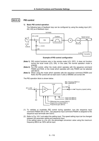
- 1. 6. Control Functions and Parameter Settings B43-0~A PID control 1) Basic PID control operation The following type of feedback loop can be configured by using the analog input (AI1, AI2, AI3) as a feedback input. Converter AI1 or AI2 VAT300S 0-10V or 4-20mA 0-10V Speed sensor PumpM Cushion AI3 C12-9 PID + – Example of PID control configuration (Note 1) PID control functions only in the remote mode (LCL OFF). It does not function during the local mode (LCL ON). In this case, the normal operation mode is entered. (Note 2) For PID control, either the mode which operates with the sequence command PIDEN and RUN, or the mode which operates with only PIDEN can be selected with B43-9. (Note 3) When using the mode which operates with the sequence command PIDEN and RUN, the PID control will not start even if JOG or BRAKE are turned ON. The PID operation block is shown below. AI3 Max. frequency B00-4 or Max. speed B01-4 Differential time constant (B43-2) Integral time constant (B43-1) Proportional gain (B43-0) Frequency (speed) setting Upper limit (B43-3) Lower limit (B43-4) 0 to 100% Limit PID + – AI1 or AI2 (1) To validate or invalidate PID control during operation, turn the sequence input command PIDEN ON or OFF. The sequence input command PIDEN is assigned to the sequence input terminals with C03-C. (2) Refer to Fig. 5-9-1 and select the setting input. The speed setting input can be changed between the parameter setting and sequence input. If the setting value is a Hz unit, the percentage conversion value using the maximum frequency B00-4 as 100% will be input. 6 – 116
- 2. 6. Control Functions and Parameter Settings (3) Set the analog input to be used as the feedback input with C07-5. Set the level of the analog input to be used with C12-1, 2 for AI1 and C12-5, 6 for AI2. When inputting AI3 input, set the feedback input between 0 and 10V when C12-8 is 1, and between 0 and 5V when C12-8 is 2. (4) The internal signal (lower limit over: LLMT, upper limit over: ULMT), which indicates that the feedback value has exceeded the upper limit (B43-3) and lower limit (B43-4) can be output as a sequence. Set either 24 (LLMT) or 25 (ULMT) for C13-2 to 6. 2) Detected error determination If PID detection is defective, an error is determined and a breakdown stop (IO-C) occurs. An error is determined if when the command value is the same or higher than the error determination start level (B43-5), the detected value is the same or lower than the detected error level (B43-6), and the error condition continues for just the detected error determination time (B43-7), and a breakdown stop occurs. 3) Polarity invert flag The PID input polarity can be inverted using B43-8. The normal PID input is the command value – the detected value, however, this changes to detected value – command value when the polarity is inverted. 4) PID operation selection method The PID operation conditions can be changed using B43-9 f0. f0=1: PID operates when PIDEN=ON and RUN=ON. f0=2: PID operates when PIDEN only is ON. (PID operation continues even during stop) PID output based operation/stop can be performed using B43-9 f1. f1=1: Normal operation (Operation stop not performed by PID) f1=2: PID output is used to stop operation. Stop occurs when the PID output reaches the lower limiter. Stop occurs when the PID output reaches the lower limitter in the case when B43-9 f1 f0 = 21. Set RUN=OFF and then RUN=ON once again in order to restart operation. Stop occurs automatically when the PID output reaches the lower limitter in the case when B43-9 f1 f0 =22. Furthermore, operation is restarted when the PID output exceeds the lower limitter + hysteresis (B43-A). Set RUN=OFF to completely stop the motor. 6 – 117
- 3. 6. Control Functions and Parameter Settings B44-0~6 Multi-pump control Multi-pump control refers to a function which controls the flow passage pressure at a constant level by running pumps in parallel using one VAT300 and the VAT300' internal relay output (standard 5 points, option 4 points). The pressure step of the ON/OFF controlled pumps is interpolated by a pump that is variable-speed controlled by the VAT300, which has the PID control function. This maintains the pressure's continuation. Three types of VAT300 multi-pump control can be selected with the B40-0 setting. • B40-0=6: Main pump with no rotation function • B40-0=7: Main pump with rotation function, 1-contact method • B40-0=8: Main pump with rotation function, 2-contact method 1) B40-0=6: Main pump with no rotation function Up to 9 pumps are run in parallel using one VAT300 and the VAT300' internal relay output's 8 points. When main pump with no rotation is selected, the pump controlled with variable speed is fixed. The system configuration is shown below. AI* PID Limiter monitor M M Pump 1 M Pump 2 M Pump 3 M Pump 4 M Pump 5 M Pump 6 M Pump 7 M Pump 8 (MPO1) (MPO2) (MPO3) (MPO4) (MPO5) (MPO6) (MPO7) (MPO8) VAT300 Pressure FB (AI*) System power P P P P P P P P Pressuresensor P PSO1 PSO2 PSO3 PSO4 PSO5 PSO6 PSO7 PSO8 * MP01 to 8 are sequence outputs Example of system configuration (When operating nine ON/OFF control pumps) 6 – 118
- 4. 6. Control Functions and Parameter Settings 2) B40-0=7: Main pump with rotation function, 1-contact method Up to 8 pumps are run in parallel using one VAT300 and the VAT300' internal relay output's 8 points. When main pump with rotation is selected, the pump controlled with variable speed is switched to the least operating pump only when all pumps are stopped. The system configuration is shown below. M AI* PID Limiter monitor (MPO1) (MPO2) (MPO3) (MPO4) (MPO7) (MPO8) (MPO5) (MPO6) M Pump 1 M Pump 2 M Pump 3 M Pump 4 M Pump 5 M Pump 6 Pump 7 M Pump 8 VAT300 Pressure FB (AI*) P P P P P P P P PSO3 PSO4 PSO1 PSO2 PSO5 PSO6 PSO7 PSO8 System power Pressuresensor * MP01 to 8 are sequence outputs Example of system configuration (When operating eight ON/OFF control pumps) In the above system, if the INV/commercial changeover interlock is required, an external sequence circuit must be structured. Refer to the following diagram. VAT300 P1 P2 P3 F1 F2 F3V1 V3V2 MPO1 V1 F1 V3 V2 V1F1 V2 V3 MPO2 V2 F2 V3 V1 V2F2 V1 V3 MPO3 V3 F3 V2 V1 V3F3 V1 V2 6 – 119
- 5. 6. Control Functions and Parameter Settings 3) B40-0=8: Main pump with rotation function, 2-contact method Up to 4 pumps are run in parallel using one VAT300 and the VAT300' internal relay output's 8 points. When main pump with rotation is selected, the pump controlled with variable speed is switched to the least operating pump only when all pumps are stopped. The system configuration is shown below. AI* PPID Limiter monitor (MPO1) (MPO2) (MPO3) (MPO4) (MPO5) (MPO6) (MPO7) (MPO8) M Pump 1 VAT300 Pressure FB (AI*) M Pump 2 M Pump 3 M Pump 4 PSO3 PSO4 PSO1 PSO2 PSO5 PSO6 PSO7 PSO8 P P P System power Pressuresensor * MP01 to 8 are sequence outputs Example of system configuration (When operating four ON/OFF control pumps) 6 – 120
- 6. 6. Control Functions and Parameter Settings 1) Multi-pump control operation An example of actual operation for the multi-pump control is shown below. ULT PID output LLT Sequence output ON OFF T4 (5) OFF (3) (2)(1) MPO1 (Pump 1) MPO2 (Pump 2) MPO3 (Pump 3) MPO4 (Pump 4) MPO5 (Pump 5) ON OFF ON ON OFF ON OFF Time (4)T2T2 T3 T1 ON/OFF control pump changeover operation (when operating five pumps) ULT : PID output upper limit value in VAT300 (B43-3). LLT : PID output lower limit value in VAT300 (B43-4). T1 : Pump start holding time (B44-1) T2 : Pump stop holding time (B44-2) T3 : Continuous operation limit time (B44-3) T4 : Changeover time (B44-4) The ON/OFF control of multiple pumps is carried out so that the operation time of each pump is equal. (1) When the PID output reaches ULT and T1 is passed, the auxiliary pump 2 (MPO2) with the shortest operation time turns ON. (2) When the PID output reaches ULT and T2 is passed, the auxiliary pump 1 (MPO1) with the shortest operation time turns OFF. (3) Following (2), when the PID output matches LLT for the time of T2, the auxiliary pump 3 (MPO3) with the longest operation time turns OFF. (4) When the time that the PID output and LLT match does not reach T2, the pump OFF control will not be carried out. • Pump changeover function using continuous operation limit (B44-3) (5) When the time that the auxiliary pump's ON/OFF control is not carried out reaches T3, the pump 4 (MPO4) with the longest operation time within all of the auxiliary pumps turns OFF, and the pump 5 (MPO5) with the shortest operation time will turn ON after T4. If B44-3 is set to 0, changeover following the continuous operation limit is prohibited. The variable speed control pump will not change even if the continuous operation limit time is exceeded. 6 – 121
- 7. 6. Control Functions and Parameter Settings • Main pump rotation function (6) When the main pump rotation function is enabled, the variable speed control pump will change to the pump with the shortest operation time of all pump only when all pumps are stopped. When the power is turned ON, pump 1 is always set as the variable speed control pump. (7) Only when B40-0=8 (2-contact method) is selected, and the INV drive pump changes to the commercial power drive or vice versa, a dead time is provided to prevent a current back flow from the motor. Both commercial power relay contacts are OFF during the dead time zone. The dead time zone can be set with B44-5. Other restrictions related to the pump's ON/OFF control are given below. (8) When the PID output reaches ULT, the pumps turn ON in order of the shortest running time upwards based on the regulation in (1). However, when all pumps are ON, and the pump operation run time has been exceeded, a minor fault turns ON as an upper limit alert. The minor fault signal is displayed at D05-0 at this time. (9) When the PID output reaches LLT, the pumps will sequentially turn OFF from the pump having the longest operation time following the restriction (2) in the previous page. However, if there are no pumps to turn OFF, the VAT300 will stop. After the pump stop hold time has passed, the minor fault turns ON as a lower limit alert, and is displayed at D05-0 as the monitor. When the PID output rises and leaves LLT, the VAT300 will resume operation. The FWD and REV LEDs will flicker during the automatic stop operation. MPO1 (Pump 1) MPO2 (Pump 2) MPO3 (Pump 3) VAT300 PID output LLT ON ON ON Operation Stop Restart (8) Time T2 T2 T2 T2 VAT300 automatic operation/stop (when there are three ON/OFF control pumps) (10) When B43-9: f0=1 (PID operation method = PIDEN + RUN), all commands to the pump are turned OFF at the same time the operation command (RUN) to the inverter is turned OFF. (11) When B43-9: f0=2 (PID operation method = PIDEN only), only the INV drive pump stops, even when the operation command (RUN) to the inverter is turned OFF, and the control pump continues to turn ON and OFF with PID output. 6 – 122
- 8. 6. Control Functions and Parameter Settings (12) The following operations are performed when a fault occurs at the inverter. When B43-9: f0=1 (PID operation method = PIDEN + RUN): • The pump ON/OFF commands are maintained provided that the operation command (RUN) ON status is maintained. The control pump is not turned ON and OFF, and neither is pump switching performed as time passes. • When the operation command (RUN) is turned OFF, all commands to the pump are turned OFF. When B43-9: f0=2 (PID operation method = PIDEN): • The pump ON/OFF commands are maintained regardless of whether the operation command (RUN) is turned ON or OFF, and the control pump continues to turn ON and OFF with PID output. • All commands to the pump are turned OFF when PIDEN is turned OFF. (13) When the inverter's power is turned OFF, the operation time history for each pump will be lost. 2) Preparation for operation (1) Set the number of pumps to be ON/OFF controlled in parameter B44-0. One to eight units (four units when B40-0 is 8) can be set. The functions of the output signals MP01 to MP08 for multi-pump control are as follows according to the multi-pump control method. Pump No. (application) Output signal When B40-0 = 6, 7 When B40-0 = 8 Pump 1 Pump 1 (INV drive) MP01 Pump 2 Pump 1 (Commercial drive) MP02 Pump 3 Pump 2 (INV drive) MP03 Pump 4 Pump 2 (Commercial drive) MP04 Pump 5 Pump 3 (INV drive) MP05 Pump 6 Pump 3 (Commercial drive) MP06 Pump 7 Pump 4 (INV drive) MP07 Pump 8 Pump 4 (Commercial drive) MP08 Outputs MP01 to MP08 can be set to a programmable relay output terminal. Using the parameters (from C13-2 to C13-6, and from C33-0 to C33-3), set the VAT300 standard relay outputs PS01 to PS03, RA-RC, FA-FC, and the relay interface option (U30V24RYO) in relay outputs from PS04 to PS07 The pumps are turned on in the order of pump No. 1 to 8. The option (U30V24RY0) is required to use relay outputs PS04 to 7. Refer to the Instruction Manual (ST-3477) for details on U30V24RY0. (2) The PID control function is used with the multi-pump control. • Refer to the explanation on B43-0 to A for details on setting the PID control related parameters (B43-0 to A), selecting the pressure command input, and selecting the feedback input. • Multi-pump control is always carried out in the remote mode (LCL = OFF). • The operating command is issued from the external sequence input terminal (RUN). • Do not perform operation from R.RUN, F.JOG, R.JOG. If these sequence commands are turned ON, operation is possible as PID, however, the relay outputs for each pump all turn OFF. • Turn the sequence input command PIDEN ON to validate PID control. (3) Refer to the operation explanation drawing in section (1) and set the parameters B44-1 to 5. (4) By using the setting interlock function (C20-0 to 3), the VAT300 run/stop can be controlled by the pressure command input (AI1, AI2). In this case, the operation command (RUN) is always ON. Refer to the explanation on C20-0 to 3. 6 – 123
- 9. 6. Control Functions and Parameter Settings B44-6 Multi-pump control: INV control method at lower limit selection Select whether to stop the INV or continue operation when the PID output lower limit state continues. When B44-6=2: Continue is selected, the INV will continue operation without stopping in the "VAT300 automatic operation/STOP" state shown in the previous figure. B45-0~6 Traverse run Traverse is operation in which the frequency fluctuates with the pattern shown below. This is effective for evenly winding up the thread on a bobbin in a weaving system. Centerfrequency(speed) Traverse run 0 RUN ON OFF PROG ON OFF FH (B45-0) B (B45-3) C (B45-4) D (B45-2) A (B45-1) A (B45-1) D (B45-2) Traverse operation (1) Traverse run To carry out traverse run, turn the sequence command PROG ON. (Normal operation will take place if PROG is OFF.) 1) If the sequence command RUN or R RUN is turned ON, first, the frequency (speed) will increased as high as the center frequency (speed) in ramp mode (A01-0) at the center frequency (speed), and then traverse run will start. 2) When RUN (or R RUN) is turned OFF, the frequency (speed) will decreased to a stop in ramp mode (A01-1) . 3) During traverse operation, the conventional ramp, S-shape ramp, overcurrent limit (OCL) and overvoltage limit (OVL) will not function. However, these will function while accelerating or decelerating during start or stop. 4) The traverse center frequency (rotation speed) input point can be selected with C02-1. C02-1= 1,2: Analog fixed (C07-4) = 3 : Panel fixed (B45-0) = 4 : Sequence (S0, S1) = 5 : Pulse train input fixed When using traverse run, set B11-8 to 1 (selection mode setting: binary mode). If C02-1 is set to 1 or 2, the setting from an external source selected with C07-4 will be the center frequency (speed). When C02-1 is set to 4, and traverse run is being carried out by turning the PROG command ON, the following operations (2) and (3) will take place when the sequence command S0 and S1 signals are input. 6 – 124
- 10. 6. Control Functions and Parameter Settings (2) Deviated traverse X, Y operation The deviated traverse operation shown below takes place with the sequence commands S0 (X) and S1 (Y) when carrying out traverse operation with the PROG command ON. ON ON S0 (X) OFF S1 (Y) OFF 0 Y (B45-6) X (B45-5) FH (B45-0) Centerfrequency(speed) Deviated traverse (X, Y) operation The center frequency (speed) rises by X (B45-5) only while S0 (X) is ON. The center frequency (speed) lowers by Y (B45-6) only while S1 (Y) is ON. The rising and lowering timing is the traverse rising and lowering extension operation as shown above. (3) Changing the center frequency (speed) with settings from an external source While the PROG command is ON and the traverse operation is taking place, when the sequence commands S0 and S1 both turn ON, the center frequency value (speed) value will be the value set from an external source selected with C07-4. If only S0 or S1 is ON, the deviated traverse X, Y operation explained in section (2) will take place. If both S0 and S1 are turned ON, the center frequency (speed) will be the value set from the external terminal. However, the frequency will first return to the center frequency (speed) before rising or lowering to the newly set value. After that, the same operation will take place even when the setting value is changed from an external source. (4) Precautions for application 1) If the parameter No. B45-0 to 6 setting data is changed during traverse operation, the output frequency (speed) will return to the center frequency (speed) once. Then, traverse operation based on the newly set data will take place. When returning to the center frequency (speed), the output frequency (speed) will change in ramp mode (A01-0, 1). 2) The overcurrent limit (OCL) and overvoltage limit (OVL) functions will not activate during traverse operation, so carefully consider the inverter capacity, motor capacity and traverse related setting values when designing the system. 3) The output frequency (speed) is limited between 5.00 and 100.00% during traverse operation. 4) When carrying out deviated traverse, take care not to turn the S0 (X) and S1 (Y) commands ON simultaneously. If turned ON simultaneously, the (3) center frequency (speed) will change. 6 – 125
- 11. 6. Control Functions and Parameter Settings B46-0~5 External brake control The inverter brake can be turned ON and OFF in accordance with the inverter internal sequence. The external brake function contains all types of waiting time settings and an interlock function. Program setting input External brake command (MBRK) No change made RUN 0 0 7 7 3 3 0 0 B46-1 ( LB) B46-2 (BL) B46-3 (DB) ZSP B46-4 RUN error determined External brake answer (MBRK_ans) Output frequency/ motor rotation count command S-shape disabled Internal program settings External brake sequence example with program settings used (B46-0 f2=1), and brake answer (B46-5≠0.0) External brake command (MBRK) B46-4 RUN error rmined DC brake Normal DC brake time ON Output frequency/ motor rotation count command RUN B46-1 (LB) B46-2 (BL) B46-3 (DB) ZSP ON OFF ON S-shape disabled External brake sequence example with DC brake used (B46-0 f2=2), and no brake answer (B46-5=0.0) (1) External brake selection 1) Select the external brake function using B46-0 f0. 2) Select the IDET based interlock function using B46-0 f1. If B46-0 f1 = 2, a breakdown stop occurs at IO-C if IDET is not ON at the point the brake is released (immediately after LB). 3) Set the control mode during acceleration waiting time (LB, BL) using B46-0 f2. The normal operation mode is enabled when B46-0 f2 = 1. The mode changes to DC brake mode when B46-0 f2 = 2. 6 – 126
- 12. 6. Control Functions and Parameter Settings (2) All types of waiting time Set the waiting time when using external brake control. 1) Use B46-1 to set the waiting time (LB) from RUN until the brake is released. 2) Use B46-2 to set the waiting time (BL) from the point the brake is released until acceleration is commenced. When there is a brake answer (B46-5≠0.0sec), set the waiting time from after the brake answer, and if there is no brake answer (B46-5=0), set the waiting time from the point the brake release command is issued. In the case of the normal operation mode setting, changes are not made to the settings during BL, and the settings prior to BL are used. 3) Use B46-3 to set the waiting time (DB) from the point ZSP turns ON until the brake is engaged. (3) Error determination The following error determination can be made in cases other than IDET based interlock set at B46-0 f1. 1) RUN error determination when engaging brake In the case where RUN does not turn OFF in the time set at B46-4 from the time the brake is engaged, a breakdown stop occurs at the end controller due to an external brake RUN error (IO-D). Set to 0.0 sec to turn the RUN error determination OFF. 2) Brake answer error determination In the case where (MBRK) brake command and (MBRK_ans) brake answer do not match above the time set at B46-5, an external brake answer error (I0-E) occurs as an external brake breakdown, and a breakdown stop occurs. Set to 0.0 sec to turn the brake answer error determination OFF. (4) S-shape cushion pass function If the S-shape characteristics (B10-4) have been set, the S-shape characteristics are applied when engaging the external brake, and therefore there are cases when the frequency does not drop immediately. In order to avoid this, set B10-6=2 or 3 to disable the S-shape characteristics when stopping. B10-6=2: S-shape passed when program setting is 0. B10-6=3: S-shape passed when RUN command is OFF. 6 – 127
- 13. 6. Control Functions and Parameter Settings B47-0~6 Simple ASR control If the speed detection option preset board (U30V24DN1, DN2, DN3 0r DN5) is installed when V/f control is selected (C30-0=1, 2), simple ASR can be used. Simple ASR involves comparing the frequency command value and motor rotation count (frequency calculation value), and controlling the slippage frequency so that the frequency command matches the motor rotation count. + + + + + – Kp (B47-1) Z -1 Z -1 × × Slippage compensation gain (A02-5) 0 Fixed output range processingKi (B47-1,2) + – + + + Integral item set to zero for Acc/Dcc (when B47-0 f1=2) Frequency setting Speed detection value P variation rate limit (B47-3) Frequency command Simple ASR control block diagram (1) Simple ASR control is performed when B47-0 f0 = 2. (2) The integral operation is stopped when accelerating if B47-0 f1 = 2. The overshoot when the frequency is attained can be curtailed. (3) The proportional gain is set at B47-1. Increase the proportional gain to raise the motor count compliance, however, motor hunting will occur if increased too much. (4) Set the integral time constant at B47-2. Shorten the integral time constant to raise the rotation count compliance when the motor has a load, however, the overshoot will increase when the frequency is attained. (5) Set the proportional variation rate control at B47-3. Set a small value in order to avoid excess proportional rotational variations. (6) Set the compensating torque limitter at B47-4. Simple ASR output is output in a simple torque form. Set a small value for the compensating torque limitter to avoid overcompensating. (7) Set the simple ASR pole count at B47-5. (8) Set the simple ASR speed detection unit pulse count a B47-6. (9) The pick-up operation is required when restarting operation while the motor is rotating. This differs from vector control in that magnetic flux control is not performed. In order to pick up, 500msec finishing time is required in addition to pick-up standby time (C21- 2). (Note 1) Simple ASR differs from vector control in that torque limit control is not possible. (Note 2) The speed detection value displays at D00-5. 6 – 128
- 14. 6. Control Functions and Parameter Settings B50-0 ~B59-3 Pattern run function The frequency (speed), run direction and time can be changed automatically with the pattern run function.Frequency(speed) RUN Step-0 Step-1 Step-2 Step-3 Step-4 B50-2 B51-2 B52-2 B53-2 B54-2 B52-1 Time B54-1 B51-1 B50-1 (1) A max. of ten patterns can be set. Program in the B50-B59 blocks as shown below. The speed setting input point is selected with C02-0 = 4 (sequence). n is the step No. from 0 to 9. B5n-0: Run mode = 0: Stop = 1: Forward run = 2: Reverse run = 3: Final step (set when repeating before B59) B5n-1: Run frequency (speed) [%] B5n-2: Run time [sec.] B5n-3: Return destination step = 0 ~ 8 (Set the No. of the step to be executed next when B5n-0 = 3.) 6 – 129
- 15. 6. Control Functions and Parameter Settings (2) The sequence command functions will be as shown below during pattern running. RUN: Pattern run starts when this turns ON, and operation starts from the run frequency (speed) and operation time applied when the operation was previously stopped. The inverter will stop when this is turned OFF. (Note 1) The pattern running operates with the remote mode (LCL OFF). (Note 2) The R.RUN, F.JOG, and R.JOG commands are invalid during pattern running. S0: Proceeds to the next step at the edge from OFF to ON. (Skip) By turning this signal ON/OFF with S1 ON (hold), the step can be proceeded in synchronization with the peripheral machine regardless of the internal timer. S1: The internal timer operation will stop when ON. (Hold). Use this to pause the pattern run. S2: When this is turned ON, the operation will be reset to step 0. The S0 and S1 functions are valid only when RUN is ON. The S2 function is not related to the ON/OFF setting of RUN, and is valid at all times. When the mode is changed to the local mode (LCL ON), this will be reset to step 0. During pattern run, set B11-8 to 1 (selection mode setting: binary mode). (3) When using pattern run, the sequence status output (D04-4) ACC and DCC functions will change as shown below. ACC: Turns ON when the last step of the pattern run is being executed. (EOS) DCC: Operates with the reverse logic of the above ACC. (EOS) 6 – 130
- 16. 6. Control Functions and Parameter Settings B60-0 ~B76-6 Spinning frame function This function is used to perform spinning pattern operation. This differs from the previous pattern operation in that acceleration/deceleration is performed in a straight line cushion (auto setting) until the setting point is reached. Set the parameter selection B60-0 f0 to 2 (selection) to enable the spinning frame function. (Note 1) The spinning frame function is a V/f control function. Select control mode selection C30-0 f0=1. (1) Up to four Speed-Time Patterns (STP) can be set up to a maximum of fifteen steps. Each step is set at the target frequency and time taken to attain that frequency from the previous step. Set each STP end step number at B60-1~4. The time unit can be set at B60-6. This settings is valid for the STP time settings (B63- 0~B64-6, B67-0~B68-6, B71-0~B72-6, B75-0~B76-6) and Doff-End alarm time (B60-5). The frequency and time setting in each step of STP can be changed. Note that changes made to the STP settings during the step will be reflected when the step is updated. (2) STP switching can be performed using the external terminal There are four Speed-Time Patterns (STP), and they are selected at external terminal input (S0, S1, S2, S3). Use parameters B11-8 to select the binary mode and direct input mode. Binary mode (B11-8=*1) Direct input mode (B11-8=*2) Sequence command Selection STP No. Sequence command Selection STP No.S3 S2 S1 S0 S3 S2 S1 S0 * * OFF OFF STP0 OFF OFF OFF OFF Previous value OFF ON STP1 OFF OFF OFF ON STP0 ON OFF STP2 OFF OFF ON OFF STP1 ON ON STP3 OFF ON OFF OFF STP2 ON OFF OFF OFF STP3 (Note 2) STP switching cannot be performed during operation. If STP switching is performed during operation, the current pattern is maintained, and switching is performed after pattern operation is complete. 6 – 131 When STP0 is selected, and B60-1=14 B61-2 Frequency Time Normal deceleration cushion … B61-0 B61-1 B63-0 B62-5 B62-6 B63-1 B63-2 B64-6
- 17. 6. Control Functions and Parameter Settings (3) Speed-Time Pattern (STP) operation 1) STP operation is performed when the sequence command RUN is issued. (F.JOG, R.JOG inching operation cannot be performed.) Operation is commenced from the selected STP Step 0. 2) The method of stopping after the pattern ends can be selected with the function selection B60-0 f1. B60-0: f1 = 1 (automatic stop) • The inverter automatically stops after the last step is finished. Either normal deceleration ramp or coast to stop can be selected with the operation stop method (C00-1). B60-0: f1 = 2 (FRQ_SP operation) • After the last step is finished, the inverter shifts to special frequency (FRQ_SP) at the normal deceleration ramp, and continuous running. Operation at FRQ_SP continuous until the Run command turns OFF. • When the RUN command turns OFF, the inverter stops with the normal deceleration ramp or coast to stop depending on the operation stop method (C00-1). • The special frequency (FRQ_SP) can be set with parameter B60-9. …Frq0 Frequency Frq2 Frq1 RUN Operation FS C01-0 : Start frequency Normal acceleration cushion Time Doff-End alarm PRST B60-5:Doff-End alarm time Normal deceleration cushion A03-1 : DC brake time B60-9 : FRQ_SP frequency Frq1 Frq2 … Frq13 Frq14 Normal deceleration cushion A03-1 : DC brake time For automatic stop selection (B60-0=12) Frequency C01-0 : Start frequency Frq0 Frq2 Frq1 Frq1 Frq2 Frq13 Frq14 … … Normal acceleration cushion Normal deceleration cushion Normal deceleration cushion A03-1 : DC brake time A03-1 : DC brake time Time B60-5 : Doff-End alarm time FS For FRQ_SP operation selection (B60-0=22) RUN Operation Doff-End alarm PRST 6 – 132
- 18. 6. Control Functions and Parameter Settings 3) If the operation command is turned OFF during STP operation, normal deceleration cushion or free-run stop is performed. When restarting operation, after accelerating with the normal acceleration cushion until the previous stop frequency is reached, STP operation is restarted from the previous stop step and operation time. 4) When operation is stopped due to a power outage, after resuming the power, pattern operation is restarted from the frequency and time when the stop occurred. (4) Pattern operation can be reset by the external terminal input (PRST). Select the input terminal by selecting sequence input (C03-9). A stop occurs when the PRST is turned ON during STP operation. Operation is commenced from STEP0 when restarting operation. The method for stopping at pattern reset can be selected with function selection B60-0 f1. B60-0: f1 = 1 (automatic stop) • The inverter will automatically stop if PRST is turned ON during STP operation. Either normal deceleration ramp or coast to stop can be selected with the operation stop method (C00-1). B60-0: f1 = 2 (FRQ_SP operation) • If PRST is turned ON during STP operation, the inverter will shift to special frequency (FRQ_SP) at the normal deceleration ramp, and will continue running. Operation at FRQ_SP continuous until the RUN command turns OFF. • When the RUN command turns OFF, the inverter stops with the normal deceleration ramp or coast to stop depending on the operation stop method (C00- 1). (5) A Doff-End alarm is output at the final stage of the pattern. By setting the Doff-End alarm time (B60-5), the Doff-End alarm is output from the point after completion of the final step to the point going back the set time. The Doff-End alarm remains ON even after the pattern is completed. The Doff-End alarm is cleared by the PRST. Select the output terminal for the Doff-End alarm with the output selection (C13-2 to 6, C33-0 to 3). (Note 3) Even if the Doff-End alarm is ON, when the RUN signal is input, the Doff-End alarm will turn OFF and operation will start from Step 0. (Note 4) Normal acceleration/deceleration cushion switching can be performed using CSEL. The Doff-End alarm time and average frequency calculation is always performed with cushion 1 even if cushion 2 is selected. 6 – 133
- 19. 6. Control Functions and Parameter Settings (6) Spindle average frequency display (D13-3) The currently selected STP average frequency is displayed at monitor D13-3. The average frequency is obtained using the following formulae. 2 [sec]T[%])F[%](F S 00S 0 ×+ = 2 [sec]T[%])F[%](F S nn1n n ×+ = − (n: Step no.) 2 [sec]T[%]F S Dn D × = 1) Operation stop method (C00-1) =1: Free-run stop Average frequency [Hz]F [sec]T[sec]T[sec]T SSS MAX n10 n10 × +⋅⋅⋅++ +⋅⋅⋅++ = 2) Operation stop method (C00-1) =2: Deceleration stop Average frequency [Hz]F [sec]T[sec]T[sec]T[sec]T SSSS MAX Dn10 Dn10 × ++⋅⋅⋅++ ++⋅⋅⋅++ = (Note 5) At the time of FRQ_SP operation, average frequency switches to FRQ_SP. (7) Hank count display (D13-4) The current Hank count displays at monitor D13-3. The Hank count is obtained using the following formula. Gain 840 1 TFH RUNAVGC ×××= FAVG [Hz]: Average frequency TRUN [sec]: Operation time 840: 1 Hank = 840 yard It is necessary to set the gain (B60-7, B60-8) in order to display the Hank count correctly. The gain is obtained using the following formula. C R S K G 1 Pole 2 R2Gain ××××= p RS: Spindle radius [yard] Pole: Motor pole count GR: Gear ratio 1 2 N N = (N1: Motor gear count, N2: Spindle gear count) KC: Compensation coefficient (Compensate slippage etc.) 6 – 134 Normal deceleration cushion Frequency T1 T0 T2 Tn TD Time Fn S0 S1 S2 Fn-1 FS F0 F1 F2 SD Sn ⋯ Fs: Start frequency
- 20. 6. Control Functions and Parameter Settings (Note 6) The Hank count calculation is continued during operation, however, is reset to zero when the power is turned OFF. 6 – 135