SlideShare a Scribd company logo
6. Control Functions and Parameter Settings
C15-0 Attainment (ATN) detection width
The attained output ATN operation width is set.
Set with a percentage to the max. frequency
(B00-4) or max. speed (B01-4).
C15-1 Current (IDET) detection level
The current detection (IDET) operation level is
set. Set with a percentage of the rated current
(B00-6, B01-6).
A 5% hysteresis will occur with the IDET
operation.
C15-2 Speed detection (SPD 1) level - 1
C15-3 Speed detection (SPD 2) level - 2
The speed detection SPD 1 and 2 operation
level is set.
Set with a percentage to the max. frequency
(B00-4) or max. speed (B01-4).
The output frequency or the motor speed will
be the comparison target.
A 1% hysteresis will occur with SPD1 and 2
operation.
C15-4 Zero speed detection (ZSP) level
The zero speed detection ZSP operation level
is set.
Set with a percentage to the max. frequency
(B00-4) or max. speed (B01-4).
The output frequency or the motor speed will
be the comparison target.
A 1% hysteresis will occur with ZSP operation.
6 – 149
Time
IDET
ON
5%
C15-1
Output current
Time
1%
1%
SPD2
SPD1
C15-3
C15-2
Output frequency
ON
ON
ZSP
C15-4
Time
1%
Output frequency
(Motor speed)
ON
Time
ATN
ON ON
Output
frequency
(Motor
speed)
Settingfrequency
(Settingspeed)
C15-0
6. Control Functions and Parameter Settings
C15-5 RDELAY output delay time setting
Set the delay time from sequence output RUN OFF to RDELAY OFF in the sequence output
RDELAY.
Set the time with a 0.1 s unit.
If the sequence output RUN turns ON again during the delay time, the ON state will
continue. The conditions that cause DELAY to turn OFF at the subsequent RUN OFF will be
applied after the delay time elapses again.
(Note) RDELAY is reset if the power is turned OFF.
C15-6~9 EC0 to 3 output fault selection
Set the details of the fault assigned to the sequence output EC0 to 3 with the following
configuration.
0. 00. 0
Fault sub-code (0x0 to 0xF)
Fault main code (0x00 to 0x13)
0: Major fault, 1: Minor fault
C15-A~E EC0 to 3, ALM OFF delay timer
Set the output hold time for the sequence output assigned to the minor fault output
Note that 0.0 is the setting value for holding the sequence output to the input of the fault
reset signal (RST).
6 – 150
Sequence output
RUN
Sequence output
RDELAY
RDELAY output
delay time
(C15-5)
6. Control Functions and Parameter Settings
C20-0 Start/stop frequencies (speeds)
C20-1 Start/stop frequency (speed) hysteresis
C20-2 Interlock frequency (speed)
C20-3 Run delay timer
The following types of interlock can be obtained for the run RUN and R·RUN commands.
(2)
C20-2
RUN X
Hysteresis
C20-1
C20-0
Frequency (speed)
setting
Hysteresis comparator
(1)
RUN Y
ON delay timer
C20-3
(3)
RUN XRUN
R·RUN
(1) Setting start/stop function
The motor will run when the frequency (speed) setting is higher than the C20-0 setting
value, and will stop when lower.
(2) Start interlock
If the frequency (speed) setting value is larger than C20-2 when the run command
(RUN X) is ON, the motor will not start.
Use this function when the frequency setting is to be lowered when starting for safety
purposes.
Set C20-2 to 0 when not using this function.
(Note) When using the set operation start/stop and set interlock function together, set
a higher interlock frequency value than that for the set operation start/stop
frequency.
(3) Run delay timer
The motor will be delayed from the run command (RUN X) by the time set in C20-3.
C20-3
tDLY
ON
ON
RUNY
RUN
This is used for synchronization with peripheral machines such as mechanical brakes.
The run delay timer will not function in the jogging or local modes.
(Note 1) Set the parameter setting values to 0 when not using (1), (2) or (3).
(Note 2) The (1), (2) and (3) functions will not function during jogging run.
(Note 3) The (3) function will not function during the local mode.
(Note 4) When interlock is applied on (1), (2) or (3), the FWD and REV LED will flicker.
6 – 151
6. Control Functions and Parameter Settings
C21-0 Number of retries
C21-1 Retry wait time
Retry is a function that performs its own fault reset and restarts with pick-up. Set the number
of retries, and the wait time (tRW). If pick-up is not possible within the number of set times, an
IO-4 fault will occur.
The errors that are targets of retry are power module ( ), overcurrent ( ),
overvoltage ( )(Note 3)
, overload ( ), overheat ( ), and ground fault (
).
n = 3n = 2n = 1Internal
FLT
tRW
C21-1
(2) (3) (4)
(1)
Outputfrequency
Motor speed
OCOC
OC
Time
(Note 1) If C21-0=0, retry will not function.
(Note 2) During retry, FLT of the sequence output signals will not function.
(Note 3) OVT retry may not function correctly if the DC voltage drop is slow.
(Note 4) If the run command turns Off during retry, the retry will be cancelled and the FLT
of the sequence output signals will turn ON.
(Note 5) The pick-up operation is not carried out during vector control with IM sensor and
PM motor control (C30-0 f0 = 3,4).
CAUTION
When a fault occurs on an extremely rare case, this function automatically resets the fault and restarts
the operation.
If the fault occurs frequently, the inverter could be damaged, so first remove the cause of the fault.
C21-2 Pick-up wait time
The wait time tPW after the output is cut off to when the pick-up operation is started is set.
Set the time to when the motor residual voltage is abated for this parameter. (The residual
voltage is a voltage generated by the motor after the inverter output turns OFF, and will be
abated in approx. 1 to 5 seconds. This abatement time will take longer if the motor capacity
is large.)
6 – 152
(1) Waiting after trip due to
.
(2) (3) Retry with pick-up.
(4) Successful pick-up, and
completion of retry.
6. Control Functions and Parameter Settings
C21-3 Pick-up current limit value
The current limit value during pick-up is set. This setting value is applied only during pick-
up.
Normally, set 100% and use.
Adjust within the following range only when the output torque at restart is to be limited.
C21-3 Setting value ≥ Applicable motor excitation current (%) +10%
(Normally 30 to 40%)
<Pick-up operation (When V/f control is selected)>
Pick-up starts when RUN or R.RUN is ON in the PICK ON state or when the power is turned on
when auto start with pick-up is selected (C08-0=3).
The pick-up operation is carried out with the overcurrent limit function as shown below.
Re-acceleration
after V/f match
V/f
match
Pick-up
current
limit
C21-2
tPW
Output voltage
B18-0 (150%)
(100%)C21-3
Motor current
Setting frequency
Motor speed
Max.
frequencyOutput frequency
6 – 153
6. Control Functions and Parameter Settings
C21-4 V/f pick-up function selection
Select the pick-up function for when V/f control is selected (C30-0 f0 =1).
=1: No reverse run pick-up
Select this to restart the motor rotating in the same direction as the command when
restarting after an instantaneous power failure. The motor will restart with the
overcurrent limit from the maximum frequency in the same direction as the command.
=2: Reverse run pick-up enabled (FMAX)
Select this to restart the motor rotating in the same or reverse direction as the
command when restarting after an instantaneous power failure. The motor rotation
direction is detected first, and then is restarted with overcurrent limit from the
maximum frequency in the detected direction.
=3: Reverse run pick-up enabled (estimated speed)
Select this to restart the motor rotating in the same or reverse direction as the
command when restarting after an instantaneous power failure. First the motor
rotation direction and frequency are detected, and then the motor restarts with the
overcurrent limit from the frequency (detected value +10%) in the detected direction.
C21-5 Sensor-less pick-up function selection
Select the pick-up function for IM speed sensor-less vector control.
=1: Reverse run pick-up disabled, start search from NMAX
=2: Reverse run pick-up disabled, start search from setting value
=3: Reverse run pick-up enabled, start search from NMAX
C21-6 Speed estimation proportional gain for sensor-less pick-up
Set the speed estimation proportional gain used for pick-up during IM speed sensor-less
vector control.
C21-7 Speed estimation integral gain for sensor-less pick-up
Set the speed estimation integral gain used for pick-up during IM speed sensor-less vector
control.
6 – 154
6. Control Functions and Parameter Settings
C22-0 Motor overload reference (L0)
C22-1 0Hz overload (L2)
C22-2 0.7 Fbase freq. overload (L1)
C22-3 Motor overload breakdown reference
The operation reference for overload (OLT) is set.
(1) Unit overload (OL-1)
Overload protection is performed under the following conditions based on the machine
rated current reference.
The reference is judged as an overload when the C22-0 setting value is exceeded.
C30-0 f1 = 2 (Heavy-duty)
150% for one minute, 175% for 2.5 seconds
C30-0 f1 =1 (Normal-duty)
120% for one minute, 140% for 2.5 seconds
However, the overload reference is reduced by 50% at an output frequency of 1Hz.
The machine overload can be monitored at D02-2. Furthermore, analog output is
possible if the setting value 8 is selected at C13-0, 1.
(2) Motor overload (OL-3)
Use the C22-3 setting to set the trip breakdown reference current for one minute in the
case of a motor rated current (B00-6, B01-6) of 100%. When C22-3 is set to 120% for
example, if C22-0 is 100%, and 120% of the motor rated current is output, a breakdown
stop will occur due to a motor overload after one minute.
As shown in the diagram on the right, the counterclockwise limit characteristics change
by setting C22-0. The diagram on the right is an example with C22-0 set to 100% and
6 – 155
Output current
50% 100% 150%
1
2
C22-0=100%
C22-0=50%
Trip time
(minute)
Output frequency
Base freq. × 0.7 Base freq.
(B00-5, B01-5)
(L2)
(L1)
(L0)
C22-0
C22-2
C22-1
Overload reference
6. Control Functions and Parameter Settings
50% when C22-3=150%.
For the self-cooling motor, when operating at low speed, set C22-1 and C22-2 to meet
the motor characteristics. These characteristics are as shown in the diagram on the
right.
The motor overload can be monitored at D02-3. Furthermore, select setting value 15 at
C13-0, 1 to enable analog output.
C22-4 DBR overload
This parameter is for setting %ED of DB operation. When DB transistor or DBR built in the
unit is used, set the parameter within the specification.
When 0.0 is set, the protection function is disabled. When the external DB unit is used, set
to 0.0.
6 – 156
6. Control Functions and Parameter Settings
C22-5 Motor power loss braking setting
When the motor loss braking function is activated, set the voltage to increase with the base
frequency as a percentage in respect to the rated output voltage (B00-3). Normally, 50% of
the default value is set.
When the DC voltage attempts to rise due to deceleration operation or a regenerative load,
the motor loss braking function raises the inverter output voltage and decreases the motor
efficiency to prevent tripping by an overvoltage. This function is valid only when the motor
loss braking is selected with the main circuit option selection (C31-0 f0 = 2) in the V/f control
mode (C30-0 f0 = 1).
(Note 1) Take care to motor heating.
(Note 2) If the normal V/f setting is inappropriate, the motor efficiency will increase when
the voltage is increased and thus tripping by the overvoltage could occur easily.
C22-6 Carrier frequency automatic reduction function selection
Select the validity of the function to automatically reduce the carried frequency to 2kHz
when the inverter output current exceeds 110% of the unit's rated current and the cooling fin
temperature exceeds the reference value 1, and for when the cooling fin temperature
exceeds the reference value 2 regardless of the current.
C22-7 Phase failure detection function selection
Select the validity of the input/output phase failure detection function
f0: Input phase failure detection function selection
1: Function valid 2: Function invalid
f1: Output phase failure detection function selection
1: Function valid 2: Function invalid
(1) Input phase failure detection
When this function is valid, a fault will be output if the inverter output current exceeds
the level 55% or higher than the unit's rating and the DC voltage pulsation width
exceeds 15% of the rated voltage (400V series: 600V, 200V series: 300V) for approx. 3
seconds.
(2) Output phase failure detection
When this function is valid, if the output current's 3-phase average value during normal
operation exceeds 30% of the motor rated current and one of the phases has not
reached 7.5% of the motor rated current, a fault will be output. A judgment time of 0.3
seconds is required when the operation frequency is 40Hz or more, and a time of the
output cycle × 12-fold is required when the frequency is less than 40Hz.
(Example: When the output frequency is 5Hz, the judgment time is 0.2 seconds × 12
fold = 2.4 seconds)
6 – 157
6. Control Functions and Parameter Settings
C24-0 Overspeed protection level
Set the overspeed protection level. Set as a percentage in respect to the maximum
frequency (B00-4) or maximum speed (B01-4). The output frequency or motor speed is the
target for comparison.
C24-0
Output frequency
Motor speed
Motor coasting
FLT
(overspeed)
Time
ON
C24-1 Control mode changeover during speed detection error
This is valid when vector control with IM sensor (C30-0 f0 = 3) or PM motor control (C30-0
f0 = 4) is selected.
= 1: The speed detection error is not monitored.
= 2: The speed detection error is monitored, and if an error occurs, a fault (FLT) is output.
The motor then coasts to a stop.
= 3: The speed detection error is monitored, and if an error occurs, a minor fault (ALM) is
output. The control changes from the vector control with IM speed sensor to the IM
speed sensor-less vector control, and the operation is continued. When the speed
detection returns to the normal state, the control changes again from the sensor-less
vector control to the vector control with sensor, and the minor fault output is cleared.
The presence of a minor fault due to a speed detection error can be confirmed with
the minor fault monitor (D05-0). This is available only during vector control with IM
sensor.
C24-2 Speed detection error level
C24-3 Speed detection error recovery level
This is valid when C24-1 = 3.
Set as a percentage in respect to the maximum speed (B01-4).
If the deflection of the speed detection value per 2ms increases above the value set with
C24-2, it is judged as a speed detection error, and the control changes from the vector
control with sensor to the sensor-less vector control. After changing, when the deflection of
the speed estimated value for sensor-less vector control and the speed detection value
drops to below the value set with C24-3, it will be judged that the speed detection has
returned to the normal state. The control changes again from the sensor-less vector control
to the vector control with sensor.
6 – 158
6. Control Functions and Parameter Settings
C24-4 Control mode changeover during speed deviation error
C24-5 Speed deviation error level
C24-6 Speed deviation error judgment time
A speed deviation error occurs when the speed command and speed detection difference is
the same or higher than the speed deviation error level (C24-5), and this situation continues
for longer than the speed deviation error judgment time (C24-6).
C24-7 Reverse error detection level
Set the error detection level for when the motor rotates in the reverse direction of the speed
command.
Set using the base frequency as 100%.
The error is not detected when 0 is set.
C25-0 High-efficiency operation Voltage reduction time
This setting value is the time to
reduce the output voltage from the
V/f setting value to 0V after the
output frequency reaches the set
frequency.
Normally, the default value (10.0) is set. When using for loads with sudden torque
fluctuations, and the output frequency drops remarkably with the overcurrent limit function,
set an appropriately low value. If the rotation becomes unstable during the voltage reduction
or recovery operations causing a trip, set an appropriately high value.
The high-efficiency operation function is valid when V/f control is selected (C30-0 f0 = 1) or
auxiliary drive is selected.
C25-1 High-efficiency operation Voltage lower limit setting value
Set a value between 50 and 99 while
the inverter is stopped to select the
high-efficiency operation function.
When not using the high-efficiency operation function, set 100 while the inverter is stopped.
This setting value is the lower limit of the output voltage reduced when the high-efficiency
operation function is selected, and uses the V/f setting voltage (output voltage when not
using high-efficiency operation) as the reference.
Normally, the minimum value (50) is set. When using for loads with sudden torque
6 – 159
Output voltage
C25-1
(50~100)
C25-0
(0.1~30.0)
Time
100%V/f setting voltage
Reduced voltage
Frequency
C25-1
(10~100)
f
100%
Range of output voltage fluctuation with
frequency f
Lower limit for reduced output voltage
Output voltage
V/f setting voltage
6. Control Functions and Parameter Settings
fluctuations, and the output frequency drops remarkably with the overcurrent limit function,
set an appropriately high value.
6 – 160
6. Control Functions and Parameter Settings
(Note) Slipping will increase during high-efficiency operation, so it is recommended to
execute automatic tuning before operation and set the automatic torque boost
selection to valid (A02-1 = 2).
<Operation of high-efficiency operation>
Normally for the V/f constant operation, the no-load loss is large with a light load, and the
motor efficiency drops remarkably. Thus, according to the load, the output voltage is
reduced using the C25-1 setting value as the lower limit in respect to the voltage set with
V/f, and the motor efficiency is improved.
C25-2 Cooling fan ON/OFF control
=1: ON/OFF control is enabled
The cooling fan is working during the inerter operation, and it is stopped 5 minutes after
the inverter stop. When the inverter is turned On, the cooling fan is working for 10
seconds.
=2: ON/OFF control is disabled
The cooling fan is working while the inverter power is On.
C26-0 Standard serial communication setting Function selection
Select the serial communication method.
=1: Standard serial...This is VAT2000 original protocol using ASCII codes.
=2: Modbus .............High-speed communication using binary codes is possible.
C26-1 Standard serial communication setting Parameter protection function
The parameters shown with circles in the following table can be changed.
Setting
value
Parameter A
Parameter B, C
Basic Extend S/W H/W
1     
2 × × × × ×
3  × × × ×
4  ×  × ×
5  ×   ×
: Changeable × : Unchangeable
C26-2 Standard serial communication Station No.
Set the local station No. for serial communication with the range from 1 to 247.
C26-3 Standard serial communication Response timer
Set the minimum time for returning an answer after receiving a command during serial
communication.
When Modbus communication is selected, the data frame reception complete judgment
time (silent time) will be applied.
C26-4 Standard serial communication Baud rate setting
Set the baud rate for serial communication.
=1: 4800bps =2: 9600bps =3: 14400bps =4: 19200bps =5: 38400bps
=6: 1200bps =7: 2400bps
6 – 161
6. Control Functions and Parameter Settings
C26-5 Standard serial communication Stop bit setting
Set the number of stop bits for serial communication.
=1: 1bit =2: 2bit
When Modbus communication is selected, the parity setting (C26-2) has a priority. The
value is fixed to 2 bits when parity is disabled, and 1 bit when parity is enabled.
C26-6 Standard serial communication Parity setting
Set the parity for serial communication.
=1: None =2: Even =2: Odd
C26-7 Base section serial communication frequency (speed) unit setting
Set the unit used as a reference for writing and reading the frequency command (speed
setting command) value for the FW/FR command in the standard serial transmission
function or one of the function03h, 10h settings in the Modbus communication function.
Example : C26-7=0 (for 0.01Hz or 0.1min-1
unit)
Standard serial command: (G01FW00000003000) :
For V/f setting : 30.00Hz is written
For vector or PM setting : 300.0min-1
is written
Modbus command: 0110000000020400000BB8F4ED :
For V/f setting : 30.00Hz is written
For vector or PM setting : 300.0min-1
is written
Example : C26-7=2 (for 0.01% unit)
Standard serial command: (G01FW00000003000) : 30.00% is written
Modbus command: 0110000000020400000BB8F4ED: 30.00% is written
% is a percentage of when 100% is the maximum frequency (B00-4) or
maximum speed (B01-4).
When C26-7 is set between 3 and 5 unsigned, the - value is invalidated.
C28-0 Password No. function valid
Set the validity of the password No. when changing parameters.
=1: Function invalid =2: Function valid
When the password No. function is valid and the panel data protection function (C09-0) is
set to a value other than 1, 6, or 9, C09-0 will be locked (changes disabled). To unlock the
parameter, input the value recorded in Password No. Setting (C28-1) at Password NO. input
(U00-1).
C28-1 Password No. setting
Set the password No. used when the password No. function is valid. Once set the display
will return to 0, so make sure not to forget the set number. The default password No. is
"0000", but once the password has been set, it cannot be reset to the default value even if
default value load (C09-7) is executed.
6 – 162
6. Control Functions and Parameter Settings
C30-0 Control mode selection
Select the control mode. This parameter is set with the two digits f1 and f0.
f1: Select the unit overload mode.
=1: Normal-duty (120%/1min)
=2: Heavy-duty (150%/1min)
f0: Select the control mode.
=1: V/f control
=2: IM speed sensor-less vector control
=3: Vector control with IM speed sensor
=4: PM motor control with sensor
=5: Sensor-less PM motor control (for future use)
(Note) When this parameter is changed, the motor overload breakdown reference (C22-3),
overcurrent limit (B18-0), rating related parameter (B00, B01), manual torque boost
voltage (A02-2), DC brake voltage (A03-0), as well as these settings in the auxiliary
drive (B20 to 2F) will automatically be changed to the specified values when the
parameter change is set by pressing the
LCL
SET key on the operation panel. Always
set this parameter first.
C31-0 Main circuit option selection
Select the usage of the motor loss braking and DB resistor (built-in or external).
Refer to the explanation on the motor loss braking setting (C22-5) for details on the motor
loss braking function.
The motor loss braking function is valid when V/f control is selected (C30-0 f0 = 1) or
auxiliary drive is selected.
C31-1 Ground fault detection function
Set the validity of the ground fault detection function.
When this function is valid, the output current's zero phase will be detected. If higher than
the judgment value (approx. 50% of the unit rated current), a fault will be detected.
=1: Detection valid =2: Detection invalid
C31-2 UVL proportional gain
C31-3 UVL integral time constant
Set the gain for lowering the frequency at the start of UVL operation.
The UVL function will be turned OFF if the UVL proportional gain is set to 0.
Normally, a value approx. half of the motor rated slip is set for the UVL proportional gain.
If the fault is UVT instead of UVL, reduce the UVL integral time constant.
C33-0 PS04 output parameters
C33-1 PS05 output parameters
C33-2 PS06 output parameters
C33-3 PS07 output parameters
In the same way as C13-2 to 6, select the number of the signal to be output from List of
Parameters.
Refer to the Relay Option Manual for details on the output terminals.
This parameter does not appear when the relay option PCB is not mounted.
6 – 163
6. Control Functions and Parameter Settings
C34-6 Data range selection
Select the data range for the transmission input/output data.
Data Range Selection Table.
C50-0 Encoder pulse divided output setting
When using the speed detection option U30V24DN1, DN2, the signals input from the
encoder can be divided by 1/N, and output as 2-phase pulses (A, B phases) with 90° phase
difference from the PAOUT and PBOUT terminals.
Set the division ratio N with this parameter.
Adjust the setting value so that the output signal is up to 70kHz.
C50-1 2-phase, 1-phase encoder selection
Select the number of signals (2-phase, 1-phase) for the encoder being used.
C50-1 = 1:This is set when using an encoder that outputs a 2-phase pulse (A, B-phase)
having a 90° phase difference.
The rotation direction can be judged, and the speed can be stably controlled
even at low speeds.
Set the No. of pulses for one phase in the No. of encoder pulses (B01-8).
C50-2 = 2:This is set when using an encoder that outputs a 1-phase pulse.
Connect the input signal to the A or B phase input, and always leave one
phase unconnected.
The 1-phase pulse signal for a proximity sensor, etc., is converted internally
into a 2-phase signal.
With the 1-phase pulse mode, the rotation direction is recognized as the
operating command direction. The forward run and reverse run directions are
not judged.
A speed detection error could occur due to the effect of chattering in low speed
areas, so use a 2-phase encoder when carrying out low-speed run or
forward/reverse run.
(Note 1) The 1-phase pulse mode cannot be used with the PM control mode.
(Note 2) The speed detection direction (symbol) when 1-phase input is selected is
determined based on the movement direction.
(Note 3) In the case where ACR control is performed using vector control with an IM speed
sensor when 1-phase input is selected, this is identified as the rotation direction
outlined in Note 2. Exercise due caution with regards to the acceleration direction.
6 – 164
2-phase oscillator
1
2
C50-1
A-IN
B-IN
A-IN1
B-IN1
Dat a r a nge Uni t Dat a r ange Uni t
0 0d 44000d~ 0. 01Hz 0d 65535d~ 0. 1mi n
- 1
1 0d 4400d  ~ 0. 1Hz 0d 7200d~ 1mi n
- 1
2 0d 10000d~ 0. 01% 0d 10000d~ 0. 01%
3 - 32768d 32767d~ 0. 01Hz - 32768d 32767d~ 0. 1mi n
- 1
4 - 4400d 4400d~ 0. 1Hz - 7200d 7200d~ 1mi n
- 1
5 - 10000d 10000d~ 0. 01% - 10000d 10000d~ 0. 01%
6 0d 44000d~ 0. 01Hz 0d 72000d~ 0. 1mi n
- 1
7 0d 4400d  ~ 0. 1Hz 0d 7200d~ 1mi n
- 1
8 0d 10000d~ 0. 01% 0d 10000d~ 0. 01%
9 - 44000d 44000d~ 0. 01Hz - 72000d 72000d~ 0. 1mi n
- 1
10 - 4400d 4400d~ 0. 1Hz - 7200d 7200d~ 1mi n
- 1
11 - 10000d 10000d~ 0. 01% - 10000d 10000d~ 0. 01%
Se t t i ng
val ue
Si gne d
16bi t
Uns i gne d
Si gne d
Uns i gne d
32bi t
Dat a
s i z e
Si gn
Fr e que nc y s e t t i ng Spe e d s e t t i ng
6. Control Functions and Parameter Settings
C50-2 Encoder AB advance direction selection
The motor's rotation direction is judged by the advance and delay of the encoder's A and B
phase pulse phase.
Refer to the following diagram and set this parameter according to the phase relation of the
encoder's AB phase signal during forward run (CCW rotation).
(Note) If C50-2 is set to 2, set C50-3 to 0.
A phase
B phase
(a) When C50-2 is 1 (CCW rotation) (b) When C50-2 is 2 (CCW rotation)
A phase
B phase
Time Time
C50-3 Encoder ABZ pulse type selection
When using an encoder with signal specifications which cannot be handled with the C50-2
and C51-2 settings, set C50-3 and invert or interchange the signals.
(Note) When C50-2 and C51-2 are set, set C50-3 to 0 (signal invert/interchange invalid).
The signal conversion circuit will operate with the combinations shown below according to
the C50-3 setting No.
C50-3
setting
value
A-IN
Non invert
/ Invert
B-IN
Non invert
/ Invert
Z-IN
Non invert
/ Invert
AB
inter-
change
0 – – –
Inter-
change
invalid
1 Invert – –
2 – Invert –
3 Invert Invert –
4 – – Invert
5 Invert – Invert
6 – Invert Invert
7 Invert Invert Invert
8 – – –
AB inter-
change
9 Invert – –
10 – Invert –
11 Invert Invert –
12 – – Invert
13 Invert – Invert
14 – Invert Invert
15 Invert Invert Invert
C-51-0 Encoder selection
Select the type of encoder signals being used.
=1 : A, B, Z-phase + U, V, W-phase signal
=2: A, B, Z-phase + serial absolute signal
=3: A, B, Z-phase + U, V, W-phase signal (reduced wiring)
=4: SIN, COS signal
6 – 165
Pulse conversion circuit
AB
interchangeable
Non invert
A-IN1
B-IN1
Z-IN
A-phase signal
B-phase signal
Z-phase signal
6. Control Functions and Parameter Settings
C-51-1 AB phase-Z phase type selection
C-51-2 Encoder Z signal reversal
With the VAT300, the A, B and Z phase pulse encoder signals are defined as waveforms
which are generated as shown below during forward run (CCW rotation).
C51-1 is set according to the relation of the A phase signal's rising edge and Z phase signal
phase. With this setting and at a time of reverse running, the A phase signal's down edge
during the Z phase being high is the zero point.
Set C51-1 to 0 when the A phase signal's rising edge is generated while the Z phase signal
is High (Fig. (a)). In this case, the A phase signal's rising edge is the zero point (magnetic
pole position). In all other cases, set C51-1 to 1. In this case, the Z phase signal rising edge
is the zero point. (Fig. (b)) In this case, the Z phase rising edge is the zero point even at a
time of the reverse running.
If the Z phase signal needs to be inverted to match the signal definition shown below, set
C51-2 to 1.
(Note) When C51-2 is set to 1, set C50-3 to 0.
A phase
B phase
Z phase
(a) When C51-1 is 0 (CCW rotation) (b) When C51-1 is 1 (CCW rotation)
Time Time
A phase
B phase
Z phase
Zero point Zero point
Zero point
A phase
B phase
(c) When C51-1 is 0 (during CW rotation)
A phase
B phase
(d) When C51-1 is 1 (during CW rotation)
Time Time
Zero point
Z phase Z phase
C-51-3 Encoder UVW advance direction selection
C-51-6 Encoder UVW pulse type selection
Set these parameters when using an A, B, Z phase + U, V, W phase signal encoder or
reduced wiring type A, B, Z phase + U, V, W phase signal encoder.
When using the reduced wiring A, B, Z phase + U, V, W phase signal encoder, the VAT300
defines the initial signals input to the A, B, Z phases signal cables as the U, V and W phase
signals respectively.
Refer to the following diagram and set C51-3 according to the encoder's U, V, W phase
signal phase relation during forward run (CCW rotation).
6 – 166
6. Control Functions and Parameter Settings
U phase
V phase
W phase
(a) When C51-3 is 1 (CCW rotation) (b) When C51-3 is 2 (CCW rotation)
Time Time
U phase
V phase
W phase
When using an encoder with signal specifications which cannot be handled with the C51-3
setting, refer to the following diagram and table and invert the signals by setting C51-6.
When C51-3 is set to 2, set C51-6 to 0 (signal invert invalid).
C51-4 Z-IN → U phase winding phase angle
Observe the encoder's Z phase pulse and the inter-linear voltage waveform across the
motor terminal UV phases during forward run (CCW rotation), and obtain the phase angle
(electric angle) from the relation shown below using the Z phase pulse as a reference.
This parameter can be automatically adjusted with the automatic tuning function. Refer to
section 3-5-3. Refer to section 3-5-4 for the adjustment method when using the magnetic
pole estimation function.
6 – 167
Setting
No.
U-IN
Non
invert
/ Invert
V-IN
Non
invert
/ Invert
W-IN
Non
invert
/ Invert
0 – – –
1 Invert – –
2 – Invert –
3 Invert Invert –
4 – – Invert
5 Invert – Invert
6 – Invert Invert
7 Invert Invert Invert
Time
U
Invert
U-IN
V-IN
W-IN
During CCW rotation
Pulse conversion circuit
V
W
6. Control Functions and Parameter Settings
Relation of encoder Z phase pulse and PM motor induced electromotive waveform phase
(during CCW rotation)
Z-phase
C51-4
Vuv
Vu Vv
30°
Time
PM motor induced
electromotive
waveform
6 – 168
6. Control Functions and Parameter Settings
C51-5 Z-IN → U pulse angle
1) When using A, B, Z, phase + U, V, W phase signals or reduced wiring A, B, Z phase +
U, V, W phase signals
If there is a phase difference between the Z phase pulse and U phase pulse of the
encoder in use, set the phase difference in C51-5.
Set "0°" if there is no phase difference between the Z phase and U phase pulses.
60°
180°C51-5
Time
Encoder's Z phase and U, V, W phase signals (during CCW rotation)
Z-phase
U-phase
V-phase
W-phase
2) When using A, B, Z phase + serial absolute signals
If there is a phase difference between the Z phase pulse and serial absolute signal zero
point, set that phase difference with an angle unit.
0
C51-5
Time
Encoder's Z phase and serial absolute signal (during CCW rotation)
Z-phase
Serial signal
3) When using sine wave signals
Set the phase of the sine wave signal when the encoder's Z phase pulse is generated in
C51-5.
90°
C51-5
Time
Encoder's Z phase and sine wave signal (during CCW rotation)
Z-phase
SIN signal
COS signal
6 – 169
6. Control Functions and Parameter Settings
C51-7 UVW measurement start wait time [For reduced wiring ABZUVW]
C51-8 UVW measurement end time [For reduced wiring ABZUVW]
C51-9 ABZ measurement start wait time [For reduced wiring ABZUVW]
These parameters are set when using the reduced wiring type A, B, Z phase + U, V, W
phase signal encoder. Set the parameters according to the specifications of the encoder in
use.
When the power is turned ON to the encoder, the A, B and Z phase signal cables are at a
high impedance (hereinafter, HI-Z). Set the UVW signal measurement start time in C51-7
using the time that the three signal cables are released from the high impedance state as a
reference.
Set the UVW signal measurement end time in C51-8 using the UVW signal measurement
start time (C51-7) as a reference.
(If the UVW signal cannot be measured within this time, the fault "SP-6" will be output.)
Set the time to start control with the ABZ signal in C51-9 using the UVW signal
measurement end time (C51-8) as a reference.
(Note) The timer runs at a 2ms cycle, so all times set here must be as even umber.
Encoder output signal
Time
UVW signal
measurement
start wait
(51-7)
UVW signal
measurement
time
(C51-8)
ABZ signal
measurement
start wait time
(C51-9)
UVW signal output ABZ signal output
HI-Z
Encoder power
Inverter reception state
UVW signal
measurement
ABZ signal
measurement
6 – 170

More Related Content

What's hot

06 vat300 e_c3-1_rev_b
06 vat300 e_c3-1_rev_b06 vat300 e_c3-1_rev_b
06 vat300 e_c3-1_rev_b
Dien Ha The
 
09 vat300 e_c3-4-4_rev_a
09 vat300 e_c3-4-4_rev_a09 vat300 e_c3-4-4_rev_a
09 vat300 e_c3-4-4_rev_a
Dien Ha The
 
Cataloge ge 3.control and_automation_dienhathe.com-4_16_vat300_e_c6-6-1_rev_a
Cataloge ge 3.control and_automation_dienhathe.com-4_16_vat300_e_c6-6-1_rev_aCataloge ge 3.control and_automation_dienhathe.com-4_16_vat300_e_c6-6-1_rev_a
Cataloge ge 3.control and_automation_dienhathe.com-4_16_vat300_e_c6-6-1_rev_a
Dien Ha The
 
Catalog Frenic mini(NEW) -www.haophuong.com
Catalog Frenic mini(NEW) -www.haophuong.comCatalog Frenic mini(NEW) -www.haophuong.com
Catalog Frenic mini(NEW) -www.haophuong.com
CTY TNHH HẠO PHƯƠNG
 
Catalog lift hpc
Catalog lift hpcCatalog lift hpc
Catalog lift hpc
CTY TNHH HẠO PHƯƠNG
 
Iai erc3 cj0184 4-a-ust-2-0214
Iai erc3 cj0184 4-a-ust-2-0214Iai erc3 cj0184 4-a-ust-2-0214
Iai erc3 cj0184 4-a-ust-2-0214
Electromate
 
Operation of hydro power plants
Operation of hydro power plants Operation of hydro power plants
Operation of hydro power plants
DINESHPRASAD39
 
Bien tan-mini
Bien tan-miniBien tan-mini
Frenic mega
Frenic mega Frenic mega
Frenic5000 vg7s 405c
Frenic5000 vg7s 405cFrenic5000 vg7s 405c
Frenic5000 vg7s 405c
CTY TNHH HẠO PHƯƠNG
 
07 vat300 e_c3-4-2_rev_b
07 vat300 e_c3-4-2_rev_b07 vat300 e_c3-4-2_rev_b
07 vat300 e_c3-4-2_rev_b
Dien Ha The
 
Cataloge ge 3.control and_automation_dienhathe.com-4_12_vat300_e_c4-5_rev_a
Cataloge ge 3.control and_automation_dienhathe.com-4_12_vat300_e_c4-5_rev_aCataloge ge 3.control and_automation_dienhathe.com-4_12_vat300_e_c4-5_rev_a
Cataloge ge 3.control and_automation_dienhathe.com-4_12_vat300_e_c4-5_rev_a
Dien Ha The
 
Frenic hvac catalog
Frenic hvac catalogFrenic hvac catalog
Frenic hvac catalog
CTY TNHH HẠO PHƯƠNG
 

What's hot (13)

06 vat300 e_c3-1_rev_b
06 vat300 e_c3-1_rev_b06 vat300 e_c3-1_rev_b
06 vat300 e_c3-1_rev_b
 
09 vat300 e_c3-4-4_rev_a
09 vat300 e_c3-4-4_rev_a09 vat300 e_c3-4-4_rev_a
09 vat300 e_c3-4-4_rev_a
 
Cataloge ge 3.control and_automation_dienhathe.com-4_16_vat300_e_c6-6-1_rev_a
Cataloge ge 3.control and_automation_dienhathe.com-4_16_vat300_e_c6-6-1_rev_aCataloge ge 3.control and_automation_dienhathe.com-4_16_vat300_e_c6-6-1_rev_a
Cataloge ge 3.control and_automation_dienhathe.com-4_16_vat300_e_c6-6-1_rev_a
 
Catalog Frenic mini(NEW) -www.haophuong.com
Catalog Frenic mini(NEW) -www.haophuong.comCatalog Frenic mini(NEW) -www.haophuong.com
Catalog Frenic mini(NEW) -www.haophuong.com
 
Catalog lift hpc
Catalog lift hpcCatalog lift hpc
Catalog lift hpc
 
Iai erc3 cj0184 4-a-ust-2-0214
Iai erc3 cj0184 4-a-ust-2-0214Iai erc3 cj0184 4-a-ust-2-0214
Iai erc3 cj0184 4-a-ust-2-0214
 
Operation of hydro power plants
Operation of hydro power plants Operation of hydro power plants
Operation of hydro power plants
 
Bien tan-mini
Bien tan-miniBien tan-mini
Bien tan-mini
 
Frenic mega
Frenic mega Frenic mega
Frenic mega
 
Frenic5000 vg7s 405c
Frenic5000 vg7s 405cFrenic5000 vg7s 405c
Frenic5000 vg7s 405c
 
07 vat300 e_c3-4-2_rev_b
07 vat300 e_c3-4-2_rev_b07 vat300 e_c3-4-2_rev_b
07 vat300 e_c3-4-2_rev_b
 
Cataloge ge 3.control and_automation_dienhathe.com-4_12_vat300_e_c4-5_rev_a
Cataloge ge 3.control and_automation_dienhathe.com-4_12_vat300_e_c4-5_rev_aCataloge ge 3.control and_automation_dienhathe.com-4_12_vat300_e_c4-5_rev_a
Cataloge ge 3.control and_automation_dienhathe.com-4_12_vat300_e_c4-5_rev_a
 
Frenic hvac catalog
Frenic hvac catalogFrenic hvac catalog
Frenic hvac catalog
 

Similar to Cataloge ge 3.control and_automation-21_vat300_e_c6-6-4_2_rev_a

Cataloge ge 3.control and_automation-17_vat300_e_c6-6-2_rev_a
Cataloge ge 3.control and_automation-17_vat300_e_c6-6-2_rev_aCataloge ge 3.control and_automation-17_vat300_e_c6-6-2_rev_a
Cataloge ge 3.control and_automation-17_vat300_e_c6-6-2_rev_a
Dien Ha The
 
Cataloge ge 3.control and_automation-20_vat300_e_c6-6-4_1_rev_b
Cataloge ge 3.control and_automation-20_vat300_e_c6-6-4_1_rev_bCataloge ge 3.control and_automation-20_vat300_e_c6-6-4_1_rev_b
Cataloge ge 3.control and_automation-20_vat300_e_c6-6-4_1_rev_b
Dien Ha The
 
Cataloge ge 3.control and_automation-15_vat300_e_c6-1_rev_d
Cataloge ge 3.control and_automation-15_vat300_e_c6-1_rev_dCataloge ge 3.control and_automation-15_vat300_e_c6-1_rev_d
Cataloge ge 3.control and_automation-15_vat300_e_c6-1_rev_d
Thuan Kieu
 
Cataloge ge 3.control and_automation-15_vat300_e_c6-1_rev_d
Cataloge ge 3.control and_automation-15_vat300_e_c6-1_rev_dCataloge ge 3.control and_automation-15_vat300_e_c6-1_rev_d
Cataloge ge 3.control and_automation-15_vat300_e_c6-1_rev_d
Dien Ha The
 
Cataloge ge 3.control and_automation-16_vat300_e_c6-6-1_rev_a
Cataloge ge 3.control and_automation-16_vat300_e_c6-6-1_rev_aCataloge ge 3.control and_automation-16_vat300_e_c6-6-1_rev_a
Cataloge ge 3.control and_automation-16_vat300_e_c6-6-1_rev_a
Dien Ha The
 
BLD-AC1000S.pdf
BLD-AC1000S.pdfBLD-AC1000S.pdf
BLD-AC1000S.pdf
STEPPERONLINE
 
Affinity quick start guide issue 3
Affinity quick start guide issue 3Affinity quick start guide issue 3
Affinity quick start guide issue 3
Toàn Huỳnh
 
Mitsubishi ac servos melservo j4 solutions press-fit machine-dienhathe.vn
Mitsubishi ac servos melservo j4 solutions press-fit machine-dienhathe.vnMitsubishi ac servos melservo j4 solutions press-fit machine-dienhathe.vn
Mitsubishi ac servos melservo j4 solutions press-fit machine-dienhathe.vn
Dien Ha The
 
Cataloge ge 3.control and_automation_dienhathe.com-4_14_vat300_e_c5-8_rev_b
Cataloge ge 3.control and_automation_dienhathe.com-4_14_vat300_e_c5-8_rev_bCataloge ge 3.control and_automation_dienhathe.com-4_14_vat300_e_c5-8_rev_b
Cataloge ge 3.control and_automation_dienhathe.com-4_14_vat300_e_c5-8_rev_b
Dien Ha The
 
Cataloge ge 3.control and_automation-14_vat300_e_c5-8_rev_b
Cataloge ge 3.control and_automation-14_vat300_e_c5-8_rev_bCataloge ge 3.control and_automation-14_vat300_e_c5-8_rev_b
Cataloge ge 3.control and_automation-14_vat300_e_c5-8_rev_b
Dien Ha The
 
Mitsubishi inverter fr-s500 catalog-dienhathe.vn
Mitsubishi inverter fr-s500 catalog-dienhathe.vnMitsubishi inverter fr-s500 catalog-dienhathe.vn
Mitsubishi inverter fr-s500 catalog-dienhathe.vn
Dien Ha The
 
193 td012 -en-p
193 td012 -en-p193 td012 -en-p
193 td012 -en-p
shiju bhaskar
 
BLD-AC750S.pdf
BLD-AC750S.pdfBLD-AC750S.pdf
BLD-AC750S.pdf
STEPPERONLINE
 
Advanced motion controls azbe40a8
Advanced motion controls azbe40a8Advanced motion controls azbe40a8
Advanced motion controls azbe40a8
Electromate
 
Mitsubishi ac servos melservo j4 solutions film slitting machine-dienhathe.vn
Mitsubishi ac servos melservo j4 solutions film slitting machine-dienhathe.vnMitsubishi ac servos melservo j4 solutions film slitting machine-dienhathe.vn
Mitsubishi ac servos melservo j4 solutions film slitting machine-dienhathe.vn
Dien Ha The
 
Delta ia asda-a2_speed
Delta ia asda-a2_speedDelta ia asda-a2_speed
Delta ia asda-a2_speed
Rodrigo Adur
 
Advanced motion controls azbe10a20
Advanced motion controls azbe10a20Advanced motion controls azbe10a20
Advanced motion controls azbe10a20
Electromate
 
Biến tần LS iG5 - Tài liệu biến tần LS iG5 (English manual, P.1)
Biến tần LS iG5 - Tài liệu biến tần LS iG5 (English manual, P.1)Biến tần LS iG5 - Tài liệu biến tần LS iG5 (English manual, P.1)
Biến tần LS iG5 - Tài liệu biến tần LS iG5 (English manual, P.1)
Công ty TNHH Kỹ Thuật Tự Động HƯNG PHÚ - HƯNG PHÚ Automation
 

Similar to Cataloge ge 3.control and_automation-21_vat300_e_c6-6-4_2_rev_a (20)

Cataloge ge 3.control and_automation-17_vat300_e_c6-6-2_rev_a
Cataloge ge 3.control and_automation-17_vat300_e_c6-6-2_rev_aCataloge ge 3.control and_automation-17_vat300_e_c6-6-2_rev_a
Cataloge ge 3.control and_automation-17_vat300_e_c6-6-2_rev_a
 
Cataloge ge 3.control and_automation-20_vat300_e_c6-6-4_1_rev_b
Cataloge ge 3.control and_automation-20_vat300_e_c6-6-4_1_rev_bCataloge ge 3.control and_automation-20_vat300_e_c6-6-4_1_rev_b
Cataloge ge 3.control and_automation-20_vat300_e_c6-6-4_1_rev_b
 
Cataloge ge 3.control and_automation-15_vat300_e_c6-1_rev_d
Cataloge ge 3.control and_automation-15_vat300_e_c6-1_rev_dCataloge ge 3.control and_automation-15_vat300_e_c6-1_rev_d
Cataloge ge 3.control and_automation-15_vat300_e_c6-1_rev_d
 
Cataloge ge 3.control and_automation-15_vat300_e_c6-1_rev_d
Cataloge ge 3.control and_automation-15_vat300_e_c6-1_rev_dCataloge ge 3.control and_automation-15_vat300_e_c6-1_rev_d
Cataloge ge 3.control and_automation-15_vat300_e_c6-1_rev_d
 
Cataloge ge 3.control and_automation-16_vat300_e_c6-6-1_rev_a
Cataloge ge 3.control and_automation-16_vat300_e_c6-6-1_rev_aCataloge ge 3.control and_automation-16_vat300_e_c6-6-1_rev_a
Cataloge ge 3.control and_automation-16_vat300_e_c6-6-1_rev_a
 
BLD-AC1000S.pdf
BLD-AC1000S.pdfBLD-AC1000S.pdf
BLD-AC1000S.pdf
 
Affinity quick start guide issue 3
Affinity quick start guide issue 3Affinity quick start guide issue 3
Affinity quick start guide issue 3
 
Mitsubishi ac servos melservo j4 solutions press-fit machine-dienhathe.vn
Mitsubishi ac servos melservo j4 solutions press-fit machine-dienhathe.vnMitsubishi ac servos melservo j4 solutions press-fit machine-dienhathe.vn
Mitsubishi ac servos melservo j4 solutions press-fit machine-dienhathe.vn
 
Cataloge ge 3.control and_automation_dienhathe.com-4_14_vat300_e_c5-8_rev_b
Cataloge ge 3.control and_automation_dienhathe.com-4_14_vat300_e_c5-8_rev_bCataloge ge 3.control and_automation_dienhathe.com-4_14_vat300_e_c5-8_rev_b
Cataloge ge 3.control and_automation_dienhathe.com-4_14_vat300_e_c5-8_rev_b
 
Cataloge ge 3.control and_automation-14_vat300_e_c5-8_rev_b
Cataloge ge 3.control and_automation-14_vat300_e_c5-8_rev_bCataloge ge 3.control and_automation-14_vat300_e_c5-8_rev_b
Cataloge ge 3.control and_automation-14_vat300_e_c5-8_rev_b
 
Mitsubishi inverter fr-s500 catalog-dienhathe.vn
Mitsubishi inverter fr-s500 catalog-dienhathe.vnMitsubishi inverter fr-s500 catalog-dienhathe.vn
Mitsubishi inverter fr-s500 catalog-dienhathe.vn
 
193 td012 -en-p
193 td012 -en-p193 td012 -en-p
193 td012 -en-p
 
BLD-AC750S.pdf
BLD-AC750S.pdfBLD-AC750S.pdf
BLD-AC750S.pdf
 
Advanced motion controls azbe40a8
Advanced motion controls azbe40a8Advanced motion controls azbe40a8
Advanced motion controls azbe40a8
 
Mitsubishi ac servos melservo j4 solutions film slitting machine-dienhathe.vn
Mitsubishi ac servos melservo j4 solutions film slitting machine-dienhathe.vnMitsubishi ac servos melservo j4 solutions film slitting machine-dienhathe.vn
Mitsubishi ac servos melservo j4 solutions film slitting machine-dienhathe.vn
 
Delta ia asda-a2_speed
Delta ia asda-a2_speedDelta ia asda-a2_speed
Delta ia asda-a2_speed
 
Advanced motion controls azbe10a20
Advanced motion controls azbe10a20Advanced motion controls azbe10a20
Advanced motion controls azbe10a20
 
Biến tần LS iG5 - Tài liệu biến tần LS iG5 (English manual, P.1)
Biến tần LS iG5 - Tài liệu biến tần LS iG5 (English manual, P.1)Biến tần LS iG5 - Tài liệu biến tần LS iG5 (English manual, P.1)
Biến tần LS iG5 - Tài liệu biến tần LS iG5 (English manual, P.1)
 
Biến tần ls i g5
Biến tần ls i g5Biến tần ls i g5
Biến tần ls i g5
 
Afd Control
Afd ControlAfd Control
Afd Control
 

More from Dien Ha The

Vnd feb 2020 price list schneider (1)
Vnd feb 2020 price list schneider (1)Vnd feb 2020 price list schneider (1)
Vnd feb 2020 price list schneider (1)
Dien Ha The
 
Resize bientanfuji-dienhathe.com
Resize bientanfuji-dienhathe.comResize bientanfuji-dienhathe.com
Resize bientanfuji-dienhathe.com
Dien Ha The
 
Fed e-quick-start-up-guide-bientanfuji-dienhathe.com
Fed e-quick-start-up-guide-bientanfuji-dienhathe.comFed e-quick-start-up-guide-bientanfuji-dienhathe.com
Fed e-quick-start-up-guide-bientanfuji-dienhathe.com
Dien Ha The
 
Fed e-quick-start-manual-bientanfuji-dienhathe.com
Fed e-quick-start-manual-bientanfuji-dienhathe.comFed e-quick-start-manual-bientanfuji-dienhathe.com
Fed e-quick-start-manual-bientanfuji-dienhathe.com
Dien Ha The
 
Ls bang gia ls ap dung 20 04-2019
Ls bang gia ls ap dung 20 04-2019Ls bang gia ls ap dung 20 04-2019
Ls bang gia ls ap dung 20 04-2019
Dien Ha The
 
Mitsubishi graphic operation terminal got2000 series parts library book
Mitsubishi graphic operation terminal got2000 series parts library bookMitsubishi graphic operation terminal got2000 series parts library book
Mitsubishi graphic operation terminal got2000 series parts library book
Dien Ha The
 
Mitsubishi inverter fr-a700-instruction-manualbasic-160425031653
Mitsubishi inverter fr-a700-instruction-manualbasic-160425031653Mitsubishi inverter fr-a700-instruction-manualbasic-160425031653
Mitsubishi inverter fr-a700-instruction-manualbasic-160425031653
Dien Ha The
 
Mitsubishi graphic operation terminal got2000 series gt2103 new product release
Mitsubishi graphic operation terminal got2000 series gt2103 new product releaseMitsubishi graphic operation terminal got2000 series gt2103 new product release
Mitsubishi graphic operation terminal got2000 series gt2103 new product release
Dien Ha The
 
Mitsubishi graphic operation terminal got2000 series got mobile function quic...
Mitsubishi graphic operation terminal got2000 series got mobile function quic...Mitsubishi graphic operation terminal got2000 series got mobile function quic...
Mitsubishi graphic operation terminal got2000 series got mobile function quic...
Dien Ha The
 
Mitsubishi graphic operation terminal got2000 series drive control interactiv...
Mitsubishi graphic operation terminal got2000 series drive control interactiv...Mitsubishi graphic operation terminal got2000 series drive control interactiv...
Mitsubishi graphic operation terminal got2000 series drive control interactiv...
Dien Ha The
 
Mitsubishi inverter option catalog
Mitsubishi inverter option catalogMitsubishi inverter option catalog
Mitsubishi inverter option catalog
Dien Ha The
 
Mitsubishi low voltage ws-v series mccb and elcb
Mitsubishi low voltage ws-v series mccb and elcbMitsubishi low voltage ws-v series mccb and elcb
Mitsubishi low voltage ws-v series mccb and elcb
Dien Ha The
 
Mitsubishi graphic operation terminal got2000 series (concise)
Mitsubishi graphic operation terminal got2000 series (concise)Mitsubishi graphic operation terminal got2000 series (concise)
Mitsubishi graphic operation terminal got2000 series (concise)
Dien Ha The
 
Mitsubishi low voltage ws-v series comparison of previous and new models
Mitsubishi low voltage ws-v series comparison of previous and new modelsMitsubishi low voltage ws-v series comparison of previous and new models
Mitsubishi low voltage ws-v series comparison of previous and new models
Dien Ha The
 
Mitsubishi inverter inverter family
Mitsubishi inverter inverter familyMitsubishi inverter inverter family
Mitsubishi inverter inverter family
Dien Ha The
 
Mitsubishi low voltage miniature circuit breakers din series
Mitsubishi low voltage miniature circuit breakers din seriesMitsubishi low voltage miniature circuit breakers din series
Mitsubishi low voltage miniature circuit breakers din series
Dien Ha The
 
Mitsubishi inverter freqrol-hc2 series
Mitsubishi inverter freqrol-hc2 seriesMitsubishi inverter freqrol-hc2 series
Mitsubishi inverter freqrol-hc2 series
Dien Ha The
 
Mitsubishi low voltage mccb and elcb(ws-v series) y0720-version 1-mitsu
Mitsubishi low voltage mccb and elcb(ws-v series) y0720-version 1-mitsuMitsubishi low voltage mccb and elcb(ws-v series) y0720-version 1-mitsu
Mitsubishi low voltage mccb and elcb(ws-v series) y0720-version 1-mitsu
Dien Ha The
 
Mitsubishi inverter freqrol-f700 pj series
Mitsubishi inverter freqrol-f700 pj seriesMitsubishi inverter freqrol-f700 pj series
Mitsubishi inverter freqrol-f700 pj series
Dien Ha The
 
Mitsubishi inverter catalog-mitsubishi-inverter-option-160426021125
Mitsubishi inverter catalog-mitsubishi-inverter-option-160426021125Mitsubishi inverter catalog-mitsubishi-inverter-option-160426021125
Mitsubishi inverter catalog-mitsubishi-inverter-option-160426021125
Dien Ha The
 

More from Dien Ha The (20)

Vnd feb 2020 price list schneider (1)
Vnd feb 2020 price list schneider (1)Vnd feb 2020 price list schneider (1)
Vnd feb 2020 price list schneider (1)
 
Resize bientanfuji-dienhathe.com
Resize bientanfuji-dienhathe.comResize bientanfuji-dienhathe.com
Resize bientanfuji-dienhathe.com
 
Fed e-quick-start-up-guide-bientanfuji-dienhathe.com
Fed e-quick-start-up-guide-bientanfuji-dienhathe.comFed e-quick-start-up-guide-bientanfuji-dienhathe.com
Fed e-quick-start-up-guide-bientanfuji-dienhathe.com
 
Fed e-quick-start-manual-bientanfuji-dienhathe.com
Fed e-quick-start-manual-bientanfuji-dienhathe.comFed e-quick-start-manual-bientanfuji-dienhathe.com
Fed e-quick-start-manual-bientanfuji-dienhathe.com
 
Ls bang gia ls ap dung 20 04-2019
Ls bang gia ls ap dung 20 04-2019Ls bang gia ls ap dung 20 04-2019
Ls bang gia ls ap dung 20 04-2019
 
Mitsubishi graphic operation terminal got2000 series parts library book
Mitsubishi graphic operation terminal got2000 series parts library bookMitsubishi graphic operation terminal got2000 series parts library book
Mitsubishi graphic operation terminal got2000 series parts library book
 
Mitsubishi inverter fr-a700-instruction-manualbasic-160425031653
Mitsubishi inverter fr-a700-instruction-manualbasic-160425031653Mitsubishi inverter fr-a700-instruction-manualbasic-160425031653
Mitsubishi inverter fr-a700-instruction-manualbasic-160425031653
 
Mitsubishi graphic operation terminal got2000 series gt2103 new product release
Mitsubishi graphic operation terminal got2000 series gt2103 new product releaseMitsubishi graphic operation terminal got2000 series gt2103 new product release
Mitsubishi graphic operation terminal got2000 series gt2103 new product release
 
Mitsubishi graphic operation terminal got2000 series got mobile function quic...
Mitsubishi graphic operation terminal got2000 series got mobile function quic...Mitsubishi graphic operation terminal got2000 series got mobile function quic...
Mitsubishi graphic operation terminal got2000 series got mobile function quic...
 
Mitsubishi graphic operation terminal got2000 series drive control interactiv...
Mitsubishi graphic operation terminal got2000 series drive control interactiv...Mitsubishi graphic operation terminal got2000 series drive control interactiv...
Mitsubishi graphic operation terminal got2000 series drive control interactiv...
 
Mitsubishi inverter option catalog
Mitsubishi inverter option catalogMitsubishi inverter option catalog
Mitsubishi inverter option catalog
 
Mitsubishi low voltage ws-v series mccb and elcb
Mitsubishi low voltage ws-v series mccb and elcbMitsubishi low voltage ws-v series mccb and elcb
Mitsubishi low voltage ws-v series mccb and elcb
 
Mitsubishi graphic operation terminal got2000 series (concise)
Mitsubishi graphic operation terminal got2000 series (concise)Mitsubishi graphic operation terminal got2000 series (concise)
Mitsubishi graphic operation terminal got2000 series (concise)
 
Mitsubishi low voltage ws-v series comparison of previous and new models
Mitsubishi low voltage ws-v series comparison of previous and new modelsMitsubishi low voltage ws-v series comparison of previous and new models
Mitsubishi low voltage ws-v series comparison of previous and new models
 
Mitsubishi inverter inverter family
Mitsubishi inverter inverter familyMitsubishi inverter inverter family
Mitsubishi inverter inverter family
 
Mitsubishi low voltage miniature circuit breakers din series
Mitsubishi low voltage miniature circuit breakers din seriesMitsubishi low voltage miniature circuit breakers din series
Mitsubishi low voltage miniature circuit breakers din series
 
Mitsubishi inverter freqrol-hc2 series
Mitsubishi inverter freqrol-hc2 seriesMitsubishi inverter freqrol-hc2 series
Mitsubishi inverter freqrol-hc2 series
 
Mitsubishi low voltage mccb and elcb(ws-v series) y0720-version 1-mitsu
Mitsubishi low voltage mccb and elcb(ws-v series) y0720-version 1-mitsuMitsubishi low voltage mccb and elcb(ws-v series) y0720-version 1-mitsu
Mitsubishi low voltage mccb and elcb(ws-v series) y0720-version 1-mitsu
 
Mitsubishi inverter freqrol-f700 pj series
Mitsubishi inverter freqrol-f700 pj seriesMitsubishi inverter freqrol-f700 pj series
Mitsubishi inverter freqrol-f700 pj series
 
Mitsubishi inverter catalog-mitsubishi-inverter-option-160426021125
Mitsubishi inverter catalog-mitsubishi-inverter-option-160426021125Mitsubishi inverter catalog-mitsubishi-inverter-option-160426021125
Mitsubishi inverter catalog-mitsubishi-inverter-option-160426021125
 

Recently uploaded

Gen AI Study Jams _ For the GDSC Leads in India.pdf
Gen AI Study Jams _ For the GDSC Leads in India.pdfGen AI Study Jams _ For the GDSC Leads in India.pdf
Gen AI Study Jams _ For the GDSC Leads in India.pdf
gdsczhcet
 
Water Industry Process Automation and Control Monthly - May 2024.pdf
Water Industry Process Automation and Control Monthly - May 2024.pdfWater Industry Process Automation and Control Monthly - May 2024.pdf
Water Industry Process Automation and Control Monthly - May 2024.pdf
Water Industry Process Automation & Control
 
road safety engineering r s e unit 3.pdf
road safety engineering  r s e unit 3.pdfroad safety engineering  r s e unit 3.pdf
road safety engineering r s e unit 3.pdf
VENKATESHvenky89705
 
WATER CRISIS and its solutions-pptx 1234
WATER CRISIS and its solutions-pptx 1234WATER CRISIS and its solutions-pptx 1234
WATER CRISIS and its solutions-pptx 1234
AafreenAbuthahir2
 
HYDROPOWER - Hydroelectric power generation
HYDROPOWER - Hydroelectric power generationHYDROPOWER - Hydroelectric power generation
HYDROPOWER - Hydroelectric power generation
Robbie Edward Sayers
 
在线办理(ANU毕业证书)澳洲国立大学毕业证录取通知书一模一样
在线办理(ANU毕业证书)澳洲国立大学毕业证录取通知书一模一样在线办理(ANU毕业证书)澳洲国立大学毕业证录取通知书一模一样
在线办理(ANU毕业证书)澳洲国立大学毕业证录取通知书一模一样
obonagu
 
CFD Simulation of By-pass Flow in a HRSG module by R&R Consult.pptx
CFD Simulation of By-pass Flow in a HRSG module by R&R Consult.pptxCFD Simulation of By-pass Flow in a HRSG module by R&R Consult.pptx
CFD Simulation of By-pass Flow in a HRSG module by R&R Consult.pptx
R&R Consult
 
English lab ppt no titlespecENG PPTt.pdf
English lab ppt no titlespecENG PPTt.pdfEnglish lab ppt no titlespecENG PPTt.pdf
English lab ppt no titlespecENG PPTt.pdf
BrazilAccount1
 
一比一原版(IIT毕业证)伊利诺伊理工大学毕业证成绩单专业办理
一比一原版(IIT毕业证)伊利诺伊理工大学毕业证成绩单专业办理一比一原版(IIT毕业证)伊利诺伊理工大学毕业证成绩单专业办理
一比一原版(IIT毕业证)伊利诺伊理工大学毕业证成绩单专业办理
zwunae
 
Standard Reomte Control Interface - Neometrix
Standard Reomte Control Interface - NeometrixStandard Reomte Control Interface - Neometrix
Standard Reomte Control Interface - Neometrix
Neometrix_Engineering_Pvt_Ltd
 
Hierarchical Digital Twin of a Naval Power System
Hierarchical Digital Twin of a Naval Power SystemHierarchical Digital Twin of a Naval Power System
Hierarchical Digital Twin of a Naval Power System
Kerry Sado
 
一比一原版(SFU毕业证)西蒙菲莎大学毕业证成绩单如何办理
一比一原版(SFU毕业证)西蒙菲莎大学毕业证成绩单如何办理一比一原版(SFU毕业证)西蒙菲莎大学毕业证成绩单如何办理
一比一原版(SFU毕业证)西蒙菲莎大学毕业证成绩单如何办理
bakpo1
 
Architectural Portfolio Sean Lockwood
Architectural Portfolio Sean LockwoodArchitectural Portfolio Sean Lockwood
Architectural Portfolio Sean Lockwood
seandesed
 
Design and Analysis of Algorithms-DP,Backtracking,Graphs,B&B
Design and Analysis of Algorithms-DP,Backtracking,Graphs,B&BDesign and Analysis of Algorithms-DP,Backtracking,Graphs,B&B
Design and Analysis of Algorithms-DP,Backtracking,Graphs,B&B
Sreedhar Chowdam
 
ML for identifying fraud using open blockchain data.pptx
ML for identifying fraud using open blockchain data.pptxML for identifying fraud using open blockchain data.pptx
ML for identifying fraud using open blockchain data.pptx
Vijay Dialani, PhD
 
AP LAB PPT.pdf ap lab ppt no title specific
AP LAB PPT.pdf ap lab ppt no title specificAP LAB PPT.pdf ap lab ppt no title specific
AP LAB PPT.pdf ap lab ppt no title specific
BrazilAccount1
 
space technology lecture notes on satellite
space technology lecture notes on satellitespace technology lecture notes on satellite
space technology lecture notes on satellite
ongomchris
 
CME397 Surface Engineering- Professional Elective
CME397 Surface Engineering- Professional ElectiveCME397 Surface Engineering- Professional Elective
CME397 Surface Engineering- Professional Elective
karthi keyan
 
RAT: Retrieval Augmented Thoughts Elicit Context-Aware Reasoning in Long-Hori...
RAT: Retrieval Augmented Thoughts Elicit Context-Aware Reasoning in Long-Hori...RAT: Retrieval Augmented Thoughts Elicit Context-Aware Reasoning in Long-Hori...
RAT: Retrieval Augmented Thoughts Elicit Context-Aware Reasoning in Long-Hori...
thanhdowork
 
DESIGN A COTTON SEED SEPARATION MACHINE.docx
DESIGN A COTTON SEED SEPARATION MACHINE.docxDESIGN A COTTON SEED SEPARATION MACHINE.docx
DESIGN A COTTON SEED SEPARATION MACHINE.docx
FluxPrime1
 

Recently uploaded (20)

Gen AI Study Jams _ For the GDSC Leads in India.pdf
Gen AI Study Jams _ For the GDSC Leads in India.pdfGen AI Study Jams _ For the GDSC Leads in India.pdf
Gen AI Study Jams _ For the GDSC Leads in India.pdf
 
Water Industry Process Automation and Control Monthly - May 2024.pdf
Water Industry Process Automation and Control Monthly - May 2024.pdfWater Industry Process Automation and Control Monthly - May 2024.pdf
Water Industry Process Automation and Control Monthly - May 2024.pdf
 
road safety engineering r s e unit 3.pdf
road safety engineering  r s e unit 3.pdfroad safety engineering  r s e unit 3.pdf
road safety engineering r s e unit 3.pdf
 
WATER CRISIS and its solutions-pptx 1234
WATER CRISIS and its solutions-pptx 1234WATER CRISIS and its solutions-pptx 1234
WATER CRISIS and its solutions-pptx 1234
 
HYDROPOWER - Hydroelectric power generation
HYDROPOWER - Hydroelectric power generationHYDROPOWER - Hydroelectric power generation
HYDROPOWER - Hydroelectric power generation
 
在线办理(ANU毕业证书)澳洲国立大学毕业证录取通知书一模一样
在线办理(ANU毕业证书)澳洲国立大学毕业证录取通知书一模一样在线办理(ANU毕业证书)澳洲国立大学毕业证录取通知书一模一样
在线办理(ANU毕业证书)澳洲国立大学毕业证录取通知书一模一样
 
CFD Simulation of By-pass Flow in a HRSG module by R&R Consult.pptx
CFD Simulation of By-pass Flow in a HRSG module by R&R Consult.pptxCFD Simulation of By-pass Flow in a HRSG module by R&R Consult.pptx
CFD Simulation of By-pass Flow in a HRSG module by R&R Consult.pptx
 
English lab ppt no titlespecENG PPTt.pdf
English lab ppt no titlespecENG PPTt.pdfEnglish lab ppt no titlespecENG PPTt.pdf
English lab ppt no titlespecENG PPTt.pdf
 
一比一原版(IIT毕业证)伊利诺伊理工大学毕业证成绩单专业办理
一比一原版(IIT毕业证)伊利诺伊理工大学毕业证成绩单专业办理一比一原版(IIT毕业证)伊利诺伊理工大学毕业证成绩单专业办理
一比一原版(IIT毕业证)伊利诺伊理工大学毕业证成绩单专业办理
 
Standard Reomte Control Interface - Neometrix
Standard Reomte Control Interface - NeometrixStandard Reomte Control Interface - Neometrix
Standard Reomte Control Interface - Neometrix
 
Hierarchical Digital Twin of a Naval Power System
Hierarchical Digital Twin of a Naval Power SystemHierarchical Digital Twin of a Naval Power System
Hierarchical Digital Twin of a Naval Power System
 
一比一原版(SFU毕业证)西蒙菲莎大学毕业证成绩单如何办理
一比一原版(SFU毕业证)西蒙菲莎大学毕业证成绩单如何办理一比一原版(SFU毕业证)西蒙菲莎大学毕业证成绩单如何办理
一比一原版(SFU毕业证)西蒙菲莎大学毕业证成绩单如何办理
 
Architectural Portfolio Sean Lockwood
Architectural Portfolio Sean LockwoodArchitectural Portfolio Sean Lockwood
Architectural Portfolio Sean Lockwood
 
Design and Analysis of Algorithms-DP,Backtracking,Graphs,B&B
Design and Analysis of Algorithms-DP,Backtracking,Graphs,B&BDesign and Analysis of Algorithms-DP,Backtracking,Graphs,B&B
Design and Analysis of Algorithms-DP,Backtracking,Graphs,B&B
 
ML for identifying fraud using open blockchain data.pptx
ML for identifying fraud using open blockchain data.pptxML for identifying fraud using open blockchain data.pptx
ML for identifying fraud using open blockchain data.pptx
 
AP LAB PPT.pdf ap lab ppt no title specific
AP LAB PPT.pdf ap lab ppt no title specificAP LAB PPT.pdf ap lab ppt no title specific
AP LAB PPT.pdf ap lab ppt no title specific
 
space technology lecture notes on satellite
space technology lecture notes on satellitespace technology lecture notes on satellite
space technology lecture notes on satellite
 
CME397 Surface Engineering- Professional Elective
CME397 Surface Engineering- Professional ElectiveCME397 Surface Engineering- Professional Elective
CME397 Surface Engineering- Professional Elective
 
RAT: Retrieval Augmented Thoughts Elicit Context-Aware Reasoning in Long-Hori...
RAT: Retrieval Augmented Thoughts Elicit Context-Aware Reasoning in Long-Hori...RAT: Retrieval Augmented Thoughts Elicit Context-Aware Reasoning in Long-Hori...
RAT: Retrieval Augmented Thoughts Elicit Context-Aware Reasoning in Long-Hori...
 
DESIGN A COTTON SEED SEPARATION MACHINE.docx
DESIGN A COTTON SEED SEPARATION MACHINE.docxDESIGN A COTTON SEED SEPARATION MACHINE.docx
DESIGN A COTTON SEED SEPARATION MACHINE.docx
 

Cataloge ge 3.control and_automation-21_vat300_e_c6-6-4_2_rev_a

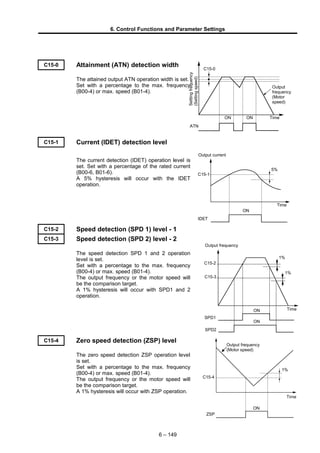
  • 1. 6. Control Functions and Parameter Settings C15-0 Attainment (ATN) detection width The attained output ATN operation width is set. Set with a percentage to the max. frequency (B00-4) or max. speed (B01-4). C15-1 Current (IDET) detection level The current detection (IDET) operation level is set. Set with a percentage of the rated current (B00-6, B01-6). A 5% hysteresis will occur with the IDET operation. C15-2 Speed detection (SPD 1) level - 1 C15-3 Speed detection (SPD 2) level - 2 The speed detection SPD 1 and 2 operation level is set. Set with a percentage to the max. frequency (B00-4) or max. speed (B01-4). The output frequency or the motor speed will be the comparison target. A 1% hysteresis will occur with SPD1 and 2 operation. C15-4 Zero speed detection (ZSP) level The zero speed detection ZSP operation level is set. Set with a percentage to the max. frequency (B00-4) or max. speed (B01-4). The output frequency or the motor speed will be the comparison target. A 1% hysteresis will occur with ZSP operation. 6 – 149 Time IDET ON 5% C15-1 Output current Time 1% 1% SPD2 SPD1 C15-3 C15-2 Output frequency ON ON ZSP C15-4 Time 1% Output frequency (Motor speed) ON Time ATN ON ON Output frequency (Motor speed) Settingfrequency (Settingspeed) C15-0
  • 2. 6. Control Functions and Parameter Settings C15-5 RDELAY output delay time setting Set the delay time from sequence output RUN OFF to RDELAY OFF in the sequence output RDELAY. Set the time with a 0.1 s unit. If the sequence output RUN turns ON again during the delay time, the ON state will continue. The conditions that cause DELAY to turn OFF at the subsequent RUN OFF will be applied after the delay time elapses again. (Note) RDELAY is reset if the power is turned OFF. C15-6~9 EC0 to 3 output fault selection Set the details of the fault assigned to the sequence output EC0 to 3 with the following configuration. 0. 00. 0 Fault sub-code (0x0 to 0xF) Fault main code (0x00 to 0x13) 0: Major fault, 1: Minor fault C15-A~E EC0 to 3, ALM OFF delay timer Set the output hold time for the sequence output assigned to the minor fault output Note that 0.0 is the setting value for holding the sequence output to the input of the fault reset signal (RST). 6 – 150 Sequence output RUN Sequence output RDELAY RDELAY output delay time (C15-5)
  • 3. 6. Control Functions and Parameter Settings C20-0 Start/stop frequencies (speeds) C20-1 Start/stop frequency (speed) hysteresis C20-2 Interlock frequency (speed) C20-3 Run delay timer The following types of interlock can be obtained for the run RUN and R·RUN commands. (2) C20-2 RUN X Hysteresis C20-1 C20-0 Frequency (speed) setting Hysteresis comparator (1) RUN Y ON delay timer C20-3 (3) RUN XRUN R·RUN (1) Setting start/stop function The motor will run when the frequency (speed) setting is higher than the C20-0 setting value, and will stop when lower. (2) Start interlock If the frequency (speed) setting value is larger than C20-2 when the run command (RUN X) is ON, the motor will not start. Use this function when the frequency setting is to be lowered when starting for safety purposes. Set C20-2 to 0 when not using this function. (Note) When using the set operation start/stop and set interlock function together, set a higher interlock frequency value than that for the set operation start/stop frequency. (3) Run delay timer The motor will be delayed from the run command (RUN X) by the time set in C20-3. C20-3 tDLY ON ON RUNY RUN This is used for synchronization with peripheral machines such as mechanical brakes. The run delay timer will not function in the jogging or local modes. (Note 1) Set the parameter setting values to 0 when not using (1), (2) or (3). (Note 2) The (1), (2) and (3) functions will not function during jogging run. (Note 3) The (3) function will not function during the local mode. (Note 4) When interlock is applied on (1), (2) or (3), the FWD and REV LED will flicker. 6 – 151
  • 4. 6. Control Functions and Parameter Settings C21-0 Number of retries C21-1 Retry wait time Retry is a function that performs its own fault reset and restarts with pick-up. Set the number of retries, and the wait time (tRW). If pick-up is not possible within the number of set times, an IO-4 fault will occur. The errors that are targets of retry are power module ( ), overcurrent ( ), overvoltage ( )(Note 3) , overload ( ), overheat ( ), and ground fault ( ). n = 3n = 2n = 1Internal FLT tRW C21-1 (2) (3) (4) (1) Outputfrequency Motor speed OCOC OC Time (Note 1) If C21-0=0, retry will not function. (Note 2) During retry, FLT of the sequence output signals will not function. (Note 3) OVT retry may not function correctly if the DC voltage drop is slow. (Note 4) If the run command turns Off during retry, the retry will be cancelled and the FLT of the sequence output signals will turn ON. (Note 5) The pick-up operation is not carried out during vector control with IM sensor and PM motor control (C30-0 f0 = 3,4). CAUTION When a fault occurs on an extremely rare case, this function automatically resets the fault and restarts the operation. If the fault occurs frequently, the inverter could be damaged, so first remove the cause of the fault. C21-2 Pick-up wait time The wait time tPW after the output is cut off to when the pick-up operation is started is set. Set the time to when the motor residual voltage is abated for this parameter. (The residual voltage is a voltage generated by the motor after the inverter output turns OFF, and will be abated in approx. 1 to 5 seconds. This abatement time will take longer if the motor capacity is large.) 6 – 152 (1) Waiting after trip due to . (2) (3) Retry with pick-up. (4) Successful pick-up, and completion of retry.
  • 5. 6. Control Functions and Parameter Settings C21-3 Pick-up current limit value The current limit value during pick-up is set. This setting value is applied only during pick- up. Normally, set 100% and use. Adjust within the following range only when the output torque at restart is to be limited. C21-3 Setting value ≥ Applicable motor excitation current (%) +10% (Normally 30 to 40%) <Pick-up operation (When V/f control is selected)> Pick-up starts when RUN or R.RUN is ON in the PICK ON state or when the power is turned on when auto start with pick-up is selected (C08-0=3). The pick-up operation is carried out with the overcurrent limit function as shown below. Re-acceleration after V/f match V/f match Pick-up current limit C21-2 tPW Output voltage B18-0 (150%) (100%)C21-3 Motor current Setting frequency Motor speed Max. frequencyOutput frequency 6 – 153
  • 6. 6. Control Functions and Parameter Settings C21-4 V/f pick-up function selection Select the pick-up function for when V/f control is selected (C30-0 f0 =1). =1: No reverse run pick-up Select this to restart the motor rotating in the same direction as the command when restarting after an instantaneous power failure. The motor will restart with the overcurrent limit from the maximum frequency in the same direction as the command. =2: Reverse run pick-up enabled (FMAX) Select this to restart the motor rotating in the same or reverse direction as the command when restarting after an instantaneous power failure. The motor rotation direction is detected first, and then is restarted with overcurrent limit from the maximum frequency in the detected direction. =3: Reverse run pick-up enabled (estimated speed) Select this to restart the motor rotating in the same or reverse direction as the command when restarting after an instantaneous power failure. First the motor rotation direction and frequency are detected, and then the motor restarts with the overcurrent limit from the frequency (detected value +10%) in the detected direction. C21-5 Sensor-less pick-up function selection Select the pick-up function for IM speed sensor-less vector control. =1: Reverse run pick-up disabled, start search from NMAX =2: Reverse run pick-up disabled, start search from setting value =3: Reverse run pick-up enabled, start search from NMAX C21-6 Speed estimation proportional gain for sensor-less pick-up Set the speed estimation proportional gain used for pick-up during IM speed sensor-less vector control. C21-7 Speed estimation integral gain for sensor-less pick-up Set the speed estimation integral gain used for pick-up during IM speed sensor-less vector control. 6 – 154
  • 7. 6. Control Functions and Parameter Settings C22-0 Motor overload reference (L0) C22-1 0Hz overload (L2) C22-2 0.7 Fbase freq. overload (L1) C22-3 Motor overload breakdown reference The operation reference for overload (OLT) is set. (1) Unit overload (OL-1) Overload protection is performed under the following conditions based on the machine rated current reference. The reference is judged as an overload when the C22-0 setting value is exceeded. C30-0 f1 = 2 (Heavy-duty) 150% for one minute, 175% for 2.5 seconds C30-0 f1 =1 (Normal-duty) 120% for one minute, 140% for 2.5 seconds However, the overload reference is reduced by 50% at an output frequency of 1Hz. The machine overload can be monitored at D02-2. Furthermore, analog output is possible if the setting value 8 is selected at C13-0, 1. (2) Motor overload (OL-3) Use the C22-3 setting to set the trip breakdown reference current for one minute in the case of a motor rated current (B00-6, B01-6) of 100%. When C22-3 is set to 120% for example, if C22-0 is 100%, and 120% of the motor rated current is output, a breakdown stop will occur due to a motor overload after one minute. As shown in the diagram on the right, the counterclockwise limit characteristics change by setting C22-0. The diagram on the right is an example with C22-0 set to 100% and 6 – 155 Output current 50% 100% 150% 1 2 C22-0=100% C22-0=50% Trip time (minute) Output frequency Base freq. × 0.7 Base freq. (B00-5, B01-5) (L2) (L1) (L0) C22-0 C22-2 C22-1 Overload reference
  • 8. 6. Control Functions and Parameter Settings 50% when C22-3=150%. For the self-cooling motor, when operating at low speed, set C22-1 and C22-2 to meet the motor characteristics. These characteristics are as shown in the diagram on the right. The motor overload can be monitored at D02-3. Furthermore, select setting value 15 at C13-0, 1 to enable analog output. C22-4 DBR overload This parameter is for setting %ED of DB operation. When DB transistor or DBR built in the unit is used, set the parameter within the specification. When 0.0 is set, the protection function is disabled. When the external DB unit is used, set to 0.0. 6 – 156
  • 9. 6. Control Functions and Parameter Settings C22-5 Motor power loss braking setting When the motor loss braking function is activated, set the voltage to increase with the base frequency as a percentage in respect to the rated output voltage (B00-3). Normally, 50% of the default value is set. When the DC voltage attempts to rise due to deceleration operation or a regenerative load, the motor loss braking function raises the inverter output voltage and decreases the motor efficiency to prevent tripping by an overvoltage. This function is valid only when the motor loss braking is selected with the main circuit option selection (C31-0 f0 = 2) in the V/f control mode (C30-0 f0 = 1). (Note 1) Take care to motor heating. (Note 2) If the normal V/f setting is inappropriate, the motor efficiency will increase when the voltage is increased and thus tripping by the overvoltage could occur easily. C22-6 Carrier frequency automatic reduction function selection Select the validity of the function to automatically reduce the carried frequency to 2kHz when the inverter output current exceeds 110% of the unit's rated current and the cooling fin temperature exceeds the reference value 1, and for when the cooling fin temperature exceeds the reference value 2 regardless of the current. C22-7 Phase failure detection function selection Select the validity of the input/output phase failure detection function f0: Input phase failure detection function selection 1: Function valid 2: Function invalid f1: Output phase failure detection function selection 1: Function valid 2: Function invalid (1) Input phase failure detection When this function is valid, a fault will be output if the inverter output current exceeds the level 55% or higher than the unit's rating and the DC voltage pulsation width exceeds 15% of the rated voltage (400V series: 600V, 200V series: 300V) for approx. 3 seconds. (2) Output phase failure detection When this function is valid, if the output current's 3-phase average value during normal operation exceeds 30% of the motor rated current and one of the phases has not reached 7.5% of the motor rated current, a fault will be output. A judgment time of 0.3 seconds is required when the operation frequency is 40Hz or more, and a time of the output cycle × 12-fold is required when the frequency is less than 40Hz. (Example: When the output frequency is 5Hz, the judgment time is 0.2 seconds × 12 fold = 2.4 seconds) 6 – 157
  • 10. 6. Control Functions and Parameter Settings C24-0 Overspeed protection level Set the overspeed protection level. Set as a percentage in respect to the maximum frequency (B00-4) or maximum speed (B01-4). The output frequency or motor speed is the target for comparison. C24-0 Output frequency Motor speed Motor coasting FLT (overspeed) Time ON C24-1 Control mode changeover during speed detection error This is valid when vector control with IM sensor (C30-0 f0 = 3) or PM motor control (C30-0 f0 = 4) is selected. = 1: The speed detection error is not monitored. = 2: The speed detection error is monitored, and if an error occurs, a fault (FLT) is output. The motor then coasts to a stop. = 3: The speed detection error is monitored, and if an error occurs, a minor fault (ALM) is output. The control changes from the vector control with IM speed sensor to the IM speed sensor-less vector control, and the operation is continued. When the speed detection returns to the normal state, the control changes again from the sensor-less vector control to the vector control with sensor, and the minor fault output is cleared. The presence of a minor fault due to a speed detection error can be confirmed with the minor fault monitor (D05-0). This is available only during vector control with IM sensor. C24-2 Speed detection error level C24-3 Speed detection error recovery level This is valid when C24-1 = 3. Set as a percentage in respect to the maximum speed (B01-4). If the deflection of the speed detection value per 2ms increases above the value set with C24-2, it is judged as a speed detection error, and the control changes from the vector control with sensor to the sensor-less vector control. After changing, when the deflection of the speed estimated value for sensor-less vector control and the speed detection value drops to below the value set with C24-3, it will be judged that the speed detection has returned to the normal state. The control changes again from the sensor-less vector control to the vector control with sensor. 6 – 158
  • 11. 6. Control Functions and Parameter Settings C24-4 Control mode changeover during speed deviation error C24-5 Speed deviation error level C24-6 Speed deviation error judgment time A speed deviation error occurs when the speed command and speed detection difference is the same or higher than the speed deviation error level (C24-5), and this situation continues for longer than the speed deviation error judgment time (C24-6). C24-7 Reverse error detection level Set the error detection level for when the motor rotates in the reverse direction of the speed command. Set using the base frequency as 100%. The error is not detected when 0 is set. C25-0 High-efficiency operation Voltage reduction time This setting value is the time to reduce the output voltage from the V/f setting value to 0V after the output frequency reaches the set frequency. Normally, the default value (10.0) is set. When using for loads with sudden torque fluctuations, and the output frequency drops remarkably with the overcurrent limit function, set an appropriately low value. If the rotation becomes unstable during the voltage reduction or recovery operations causing a trip, set an appropriately high value. The high-efficiency operation function is valid when V/f control is selected (C30-0 f0 = 1) or auxiliary drive is selected. C25-1 High-efficiency operation Voltage lower limit setting value Set a value between 50 and 99 while the inverter is stopped to select the high-efficiency operation function. When not using the high-efficiency operation function, set 100 while the inverter is stopped. This setting value is the lower limit of the output voltage reduced when the high-efficiency operation function is selected, and uses the V/f setting voltage (output voltage when not using high-efficiency operation) as the reference. Normally, the minimum value (50) is set. When using for loads with sudden torque 6 – 159 Output voltage C25-1 (50~100) C25-0 (0.1~30.0) Time 100%V/f setting voltage Reduced voltage Frequency C25-1 (10~100) f 100% Range of output voltage fluctuation with frequency f Lower limit for reduced output voltage Output voltage V/f setting voltage
  • 12. 6. Control Functions and Parameter Settings fluctuations, and the output frequency drops remarkably with the overcurrent limit function, set an appropriately high value. 6 – 160
  • 13. 6. Control Functions and Parameter Settings (Note) Slipping will increase during high-efficiency operation, so it is recommended to execute automatic tuning before operation and set the automatic torque boost selection to valid (A02-1 = 2). <Operation of high-efficiency operation> Normally for the V/f constant operation, the no-load loss is large with a light load, and the motor efficiency drops remarkably. Thus, according to the load, the output voltage is reduced using the C25-1 setting value as the lower limit in respect to the voltage set with V/f, and the motor efficiency is improved. C25-2 Cooling fan ON/OFF control =1: ON/OFF control is enabled The cooling fan is working during the inerter operation, and it is stopped 5 minutes after the inverter stop. When the inverter is turned On, the cooling fan is working for 10 seconds. =2: ON/OFF control is disabled The cooling fan is working while the inverter power is On. C26-0 Standard serial communication setting Function selection Select the serial communication method. =1: Standard serial...This is VAT2000 original protocol using ASCII codes. =2: Modbus .............High-speed communication using binary codes is possible. C26-1 Standard serial communication setting Parameter protection function The parameters shown with circles in the following table can be changed. Setting value Parameter A Parameter B, C Basic Extend S/W H/W 1      2 × × × × × 3  × × × × 4  ×  × × 5  ×   × : Changeable × : Unchangeable C26-2 Standard serial communication Station No. Set the local station No. for serial communication with the range from 1 to 247. C26-3 Standard serial communication Response timer Set the minimum time for returning an answer after receiving a command during serial communication. When Modbus communication is selected, the data frame reception complete judgment time (silent time) will be applied. C26-4 Standard serial communication Baud rate setting Set the baud rate for serial communication. =1: 4800bps =2: 9600bps =3: 14400bps =4: 19200bps =5: 38400bps =6: 1200bps =7: 2400bps 6 – 161
  • 14. 6. Control Functions and Parameter Settings C26-5 Standard serial communication Stop bit setting Set the number of stop bits for serial communication. =1: 1bit =2: 2bit When Modbus communication is selected, the parity setting (C26-2) has a priority. The value is fixed to 2 bits when parity is disabled, and 1 bit when parity is enabled. C26-6 Standard serial communication Parity setting Set the parity for serial communication. =1: None =2: Even =2: Odd C26-7 Base section serial communication frequency (speed) unit setting Set the unit used as a reference for writing and reading the frequency command (speed setting command) value for the FW/FR command in the standard serial transmission function or one of the function03h, 10h settings in the Modbus communication function. Example : C26-7=0 (for 0.01Hz or 0.1min-1 unit) Standard serial command: (G01FW00000003000) : For V/f setting : 30.00Hz is written For vector or PM setting : 300.0min-1 is written Modbus command: 0110000000020400000BB8F4ED : For V/f setting : 30.00Hz is written For vector or PM setting : 300.0min-1 is written Example : C26-7=2 (for 0.01% unit) Standard serial command: (G01FW00000003000) : 30.00% is written Modbus command: 0110000000020400000BB8F4ED: 30.00% is written % is a percentage of when 100% is the maximum frequency (B00-4) or maximum speed (B01-4). When C26-7 is set between 3 and 5 unsigned, the - value is invalidated. C28-0 Password No. function valid Set the validity of the password No. when changing parameters. =1: Function invalid =2: Function valid When the password No. function is valid and the panel data protection function (C09-0) is set to a value other than 1, 6, or 9, C09-0 will be locked (changes disabled). To unlock the parameter, input the value recorded in Password No. Setting (C28-1) at Password NO. input (U00-1). C28-1 Password No. setting Set the password No. used when the password No. function is valid. Once set the display will return to 0, so make sure not to forget the set number. The default password No. is "0000", but once the password has been set, it cannot be reset to the default value even if default value load (C09-7) is executed. 6 – 162
  • 15. 6. Control Functions and Parameter Settings C30-0 Control mode selection Select the control mode. This parameter is set with the two digits f1 and f0. f1: Select the unit overload mode. =1: Normal-duty (120%/1min) =2: Heavy-duty (150%/1min) f0: Select the control mode. =1: V/f control =2: IM speed sensor-less vector control =3: Vector control with IM speed sensor =4: PM motor control with sensor =5: Sensor-less PM motor control (for future use) (Note) When this parameter is changed, the motor overload breakdown reference (C22-3), overcurrent limit (B18-0), rating related parameter (B00, B01), manual torque boost voltage (A02-2), DC brake voltage (A03-0), as well as these settings in the auxiliary drive (B20 to 2F) will automatically be changed to the specified values when the parameter change is set by pressing the LCL SET key on the operation panel. Always set this parameter first. C31-0 Main circuit option selection Select the usage of the motor loss braking and DB resistor (built-in or external). Refer to the explanation on the motor loss braking setting (C22-5) for details on the motor loss braking function. The motor loss braking function is valid when V/f control is selected (C30-0 f0 = 1) or auxiliary drive is selected. C31-1 Ground fault detection function Set the validity of the ground fault detection function. When this function is valid, the output current's zero phase will be detected. If higher than the judgment value (approx. 50% of the unit rated current), a fault will be detected. =1: Detection valid =2: Detection invalid C31-2 UVL proportional gain C31-3 UVL integral time constant Set the gain for lowering the frequency at the start of UVL operation. The UVL function will be turned OFF if the UVL proportional gain is set to 0. Normally, a value approx. half of the motor rated slip is set for the UVL proportional gain. If the fault is UVT instead of UVL, reduce the UVL integral time constant. C33-0 PS04 output parameters C33-1 PS05 output parameters C33-2 PS06 output parameters C33-3 PS07 output parameters In the same way as C13-2 to 6, select the number of the signal to be output from List of Parameters. Refer to the Relay Option Manual for details on the output terminals. This parameter does not appear when the relay option PCB is not mounted. 6 – 163
  • 16. 6. Control Functions and Parameter Settings C34-6 Data range selection Select the data range for the transmission input/output data. Data Range Selection Table. C50-0 Encoder pulse divided output setting When using the speed detection option U30V24DN1, DN2, the signals input from the encoder can be divided by 1/N, and output as 2-phase pulses (A, B phases) with 90° phase difference from the PAOUT and PBOUT terminals. Set the division ratio N with this parameter. Adjust the setting value so that the output signal is up to 70kHz. C50-1 2-phase, 1-phase encoder selection Select the number of signals (2-phase, 1-phase) for the encoder being used. C50-1 = 1:This is set when using an encoder that outputs a 2-phase pulse (A, B-phase) having a 90° phase difference. The rotation direction can be judged, and the speed can be stably controlled even at low speeds. Set the No. of pulses for one phase in the No. of encoder pulses (B01-8). C50-2 = 2:This is set when using an encoder that outputs a 1-phase pulse. Connect the input signal to the A or B phase input, and always leave one phase unconnected. The 1-phase pulse signal for a proximity sensor, etc., is converted internally into a 2-phase signal. With the 1-phase pulse mode, the rotation direction is recognized as the operating command direction. The forward run and reverse run directions are not judged. A speed detection error could occur due to the effect of chattering in low speed areas, so use a 2-phase encoder when carrying out low-speed run or forward/reverse run. (Note 1) The 1-phase pulse mode cannot be used with the PM control mode. (Note 2) The speed detection direction (symbol) when 1-phase input is selected is determined based on the movement direction. (Note 3) In the case where ACR control is performed using vector control with an IM speed sensor when 1-phase input is selected, this is identified as the rotation direction outlined in Note 2. Exercise due caution with regards to the acceleration direction. 6 – 164 2-phase oscillator 1 2 C50-1 A-IN B-IN A-IN1 B-IN1 Dat a r a nge Uni t Dat a r ange Uni t 0 0d 44000d~ 0. 01Hz 0d 65535d~ 0. 1mi n - 1 1 0d 4400d  ~ 0. 1Hz 0d 7200d~ 1mi n - 1 2 0d 10000d~ 0. 01% 0d 10000d~ 0. 01% 3 - 32768d 32767d~ 0. 01Hz - 32768d 32767d~ 0. 1mi n - 1 4 - 4400d 4400d~ 0. 1Hz - 7200d 7200d~ 1mi n - 1 5 - 10000d 10000d~ 0. 01% - 10000d 10000d~ 0. 01% 6 0d 44000d~ 0. 01Hz 0d 72000d~ 0. 1mi n - 1 7 0d 4400d  ~ 0. 1Hz 0d 7200d~ 1mi n - 1 8 0d 10000d~ 0. 01% 0d 10000d~ 0. 01% 9 - 44000d 44000d~ 0. 01Hz - 72000d 72000d~ 0. 1mi n - 1 10 - 4400d 4400d~ 0. 1Hz - 7200d 7200d~ 1mi n - 1 11 - 10000d 10000d~ 0. 01% - 10000d 10000d~ 0. 01% Se t t i ng val ue Si gne d 16bi t Uns i gne d Si gne d Uns i gne d 32bi t Dat a s i z e Si gn Fr e que nc y s e t t i ng Spe e d s e t t i ng
  • 17. 6. Control Functions and Parameter Settings C50-2 Encoder AB advance direction selection The motor's rotation direction is judged by the advance and delay of the encoder's A and B phase pulse phase. Refer to the following diagram and set this parameter according to the phase relation of the encoder's AB phase signal during forward run (CCW rotation). (Note) If C50-2 is set to 2, set C50-3 to 0. A phase B phase (a) When C50-2 is 1 (CCW rotation) (b) When C50-2 is 2 (CCW rotation) A phase B phase Time Time C50-3 Encoder ABZ pulse type selection When using an encoder with signal specifications which cannot be handled with the C50-2 and C51-2 settings, set C50-3 and invert or interchange the signals. (Note) When C50-2 and C51-2 are set, set C50-3 to 0 (signal invert/interchange invalid). The signal conversion circuit will operate with the combinations shown below according to the C50-3 setting No. C50-3 setting value A-IN Non invert / Invert B-IN Non invert / Invert Z-IN Non invert / Invert AB inter- change 0 – – – Inter- change invalid 1 Invert – – 2 – Invert – 3 Invert Invert – 4 – – Invert 5 Invert – Invert 6 – Invert Invert 7 Invert Invert Invert 8 – – – AB inter- change 9 Invert – – 10 – Invert – 11 Invert Invert – 12 – – Invert 13 Invert – Invert 14 – Invert Invert 15 Invert Invert Invert C-51-0 Encoder selection Select the type of encoder signals being used. =1 : A, B, Z-phase + U, V, W-phase signal =2: A, B, Z-phase + serial absolute signal =3: A, B, Z-phase + U, V, W-phase signal (reduced wiring) =4: SIN, COS signal 6 – 165 Pulse conversion circuit AB interchangeable Non invert A-IN1 B-IN1 Z-IN A-phase signal B-phase signal Z-phase signal
  • 18. 6. Control Functions and Parameter Settings C-51-1 AB phase-Z phase type selection C-51-2 Encoder Z signal reversal With the VAT300, the A, B and Z phase pulse encoder signals are defined as waveforms which are generated as shown below during forward run (CCW rotation). C51-1 is set according to the relation of the A phase signal's rising edge and Z phase signal phase. With this setting and at a time of reverse running, the A phase signal's down edge during the Z phase being high is the zero point. Set C51-1 to 0 when the A phase signal's rising edge is generated while the Z phase signal is High (Fig. (a)). In this case, the A phase signal's rising edge is the zero point (magnetic pole position). In all other cases, set C51-1 to 1. In this case, the Z phase signal rising edge is the zero point. (Fig. (b)) In this case, the Z phase rising edge is the zero point even at a time of the reverse running. If the Z phase signal needs to be inverted to match the signal definition shown below, set C51-2 to 1. (Note) When C51-2 is set to 1, set C50-3 to 0. A phase B phase Z phase (a) When C51-1 is 0 (CCW rotation) (b) When C51-1 is 1 (CCW rotation) Time Time A phase B phase Z phase Zero point Zero point Zero point A phase B phase (c) When C51-1 is 0 (during CW rotation) A phase B phase (d) When C51-1 is 1 (during CW rotation) Time Time Zero point Z phase Z phase C-51-3 Encoder UVW advance direction selection C-51-6 Encoder UVW pulse type selection Set these parameters when using an A, B, Z phase + U, V, W phase signal encoder or reduced wiring type A, B, Z phase + U, V, W phase signal encoder. When using the reduced wiring A, B, Z phase + U, V, W phase signal encoder, the VAT300 defines the initial signals input to the A, B, Z phases signal cables as the U, V and W phase signals respectively. Refer to the following diagram and set C51-3 according to the encoder's U, V, W phase signal phase relation during forward run (CCW rotation). 6 – 166
  • 19. 6. Control Functions and Parameter Settings U phase V phase W phase (a) When C51-3 is 1 (CCW rotation) (b) When C51-3 is 2 (CCW rotation) Time Time U phase V phase W phase When using an encoder with signal specifications which cannot be handled with the C51-3 setting, refer to the following diagram and table and invert the signals by setting C51-6. When C51-3 is set to 2, set C51-6 to 0 (signal invert invalid). C51-4 Z-IN → U phase winding phase angle Observe the encoder's Z phase pulse and the inter-linear voltage waveform across the motor terminal UV phases during forward run (CCW rotation), and obtain the phase angle (electric angle) from the relation shown below using the Z phase pulse as a reference. This parameter can be automatically adjusted with the automatic tuning function. Refer to section 3-5-3. Refer to section 3-5-4 for the adjustment method when using the magnetic pole estimation function. 6 – 167 Setting No. U-IN Non invert / Invert V-IN Non invert / Invert W-IN Non invert / Invert 0 – – – 1 Invert – – 2 – Invert – 3 Invert Invert – 4 – – Invert 5 Invert – Invert 6 – Invert Invert 7 Invert Invert Invert Time U Invert U-IN V-IN W-IN During CCW rotation Pulse conversion circuit V W
  • 20. 6. Control Functions and Parameter Settings Relation of encoder Z phase pulse and PM motor induced electromotive waveform phase (during CCW rotation) Z-phase C51-4 Vuv Vu Vv 30° Time PM motor induced electromotive waveform 6 – 168
  • 21. 6. Control Functions and Parameter Settings C51-5 Z-IN → U pulse angle 1) When using A, B, Z, phase + U, V, W phase signals or reduced wiring A, B, Z phase + U, V, W phase signals If there is a phase difference between the Z phase pulse and U phase pulse of the encoder in use, set the phase difference in C51-5. Set "0°" if there is no phase difference between the Z phase and U phase pulses. 60° 180°C51-5 Time Encoder's Z phase and U, V, W phase signals (during CCW rotation) Z-phase U-phase V-phase W-phase 2) When using A, B, Z phase + serial absolute signals If there is a phase difference between the Z phase pulse and serial absolute signal zero point, set that phase difference with an angle unit. 0 C51-5 Time Encoder's Z phase and serial absolute signal (during CCW rotation) Z-phase Serial signal 3) When using sine wave signals Set the phase of the sine wave signal when the encoder's Z phase pulse is generated in C51-5. 90° C51-5 Time Encoder's Z phase and sine wave signal (during CCW rotation) Z-phase SIN signal COS signal 6 – 169
  • 22. 6. Control Functions and Parameter Settings C51-7 UVW measurement start wait time [For reduced wiring ABZUVW] C51-8 UVW measurement end time [For reduced wiring ABZUVW] C51-9 ABZ measurement start wait time [For reduced wiring ABZUVW] These parameters are set when using the reduced wiring type A, B, Z phase + U, V, W phase signal encoder. Set the parameters according to the specifications of the encoder in use. When the power is turned ON to the encoder, the A, B and Z phase signal cables are at a high impedance (hereinafter, HI-Z). Set the UVW signal measurement start time in C51-7 using the time that the three signal cables are released from the high impedance state as a reference. Set the UVW signal measurement end time in C51-8 using the UVW signal measurement start time (C51-7) as a reference. (If the UVW signal cannot be measured within this time, the fault "SP-6" will be output.) Set the time to start control with the ABZ signal in C51-9 using the UVW signal measurement end time (C51-8) as a reference. (Note) The timer runs at a 2ms cycle, so all times set here must be as even umber. Encoder output signal Time UVW signal measurement start wait (51-7) UVW signal measurement time (C51-8) ABZ signal measurement start wait time (C51-9) UVW signal output ABZ signal output HI-Z Encoder power Inverter reception state UVW signal measurement ABZ signal measurement 6 – 170