Download to read offline
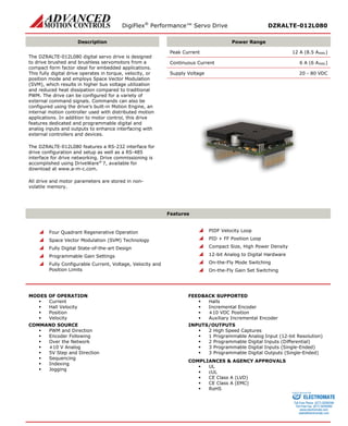
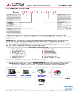

The DigiFlex® PerformanceTM Servo Drive DZRALTE-012L080 is a digital servo drive designed to drive brushed and brushless servomotors from a compact form factor. It operates in torque, velocity, or position mode using space vector modulation for higher efficiency. The drive supports a variety of command and feedback interfaces and includes programmable digital and analog inputs/outputs. It complies with relevant safety standards and has natural convection cooling in a small PCB mounted package.


