SlideShare a Scribd company logo
1 of 33
6. Control Functions and Parameter Settings
6-12 Explanation of standard serial and Modbus communication
The VAT300 is equipped with a serial transmission function using RS485 as a standard. The inverter can
be controlled with a host computer using this function.
Either the Modbus network with Modbus protocol or the VAT300 series original communication protocol
standard serial communication can be selected with the parameters.
6-12-1 Connection method
This network is configured of one host computer (master) and 1 to 32 VAT300 units (slaves).
CN2 on the basic section or TB3 is used for the connection.
Refer to section 2-4. Precautions for wiring the control signal for details on CN2 and TB3, and for the
wiring methods.
The total length of the connected cable must be within 150 meters.
By using a commercially-available RS485-RS232C converter or USB converter unit as a relay, the
inverter can be connected to a host computer equipped with a serial port or USB, such as a
commercially-available personal computer.
• Connecting the host computer and VAT300 (1-on-1)
Host computer
RS232C
RS485
VAT300 unit
CN2
or
TB3
Host computer
USB
RS485
VAT300 unit
CN2
or
TB3
DS1-1
Host computer
RS232C
RS485
VAT300 unit
CN2
or
TB3
DS1-1
RS485
USB/RS485
converter
DS1-1
RS232C/RS485
converter
CAUTION
• Do not connect both CN2 and TB3 to the host computer.
• CN2 is a 4-pole 4-core modular connector. Pay attention to the number of poles, and prepare the
cable and connector.
• Separates the communication cable from the main circuit cable and other power cables.
• A shielded twisted pair cable should be used for connecting TB3 and the host computer.
Connect the shielded twisted pair cable's shield to the TB3 SG.
• When using a 1-on-1 connection, set the inverter's resistance (DS1 No. 1 switch on basic section) to
the 120Ω side.
• When connecting the TB3 and shielded twisted pair cable, do not solder the wires which are exposed
after the sheath is peeled off.
• If the communication is distorted and not carried out properly because of noise, etc., connect a
ferrite core, etc., to the cable, and increase the noise resistance.
6 – 196
6. Control Functions and Parameter Settings
When connecting several VAT300 units, connect two wires to each TB3 terminal, and couple the
VAT300 units.
An example of the connection is shown below.
• Connecting the host computer and VAT300 (connecting several units)
VAT300 unit VAT300 unit
Host computer
TB3TB3
VAT300 unit
TB3
DS1-1 DS1-1 DS1-1
The details of the TB3 terminal section are shown below.
SG D- D+
TB3
Shielded wire
Shielded wire
Shielded
Shielded
To host computer
or inverter
To next inverter
CAUTION
• Separates the communication cable from the main circuit cable and other power cables.
• A shielded twisted pair wire should be used for connecting TB3 and the host computer.
Connect the twisted pair cable's shield to the TB3 SG.
• When using several slave units, set the resistance (DS1 No. 1 switch on basic section) of the last
inverter to 120Ω.
• When connecting the TB3 and shielded twisted pair cable, do not solder the wires which are exposed
after the sheath is peeled off.
• If the communication is distorted and not carried out properly because of noise, etc., connect a
ferrite core, etc., to the cable, and increase the noise resistance.
6 – 197
6. Control Functions and Parameter Settings
6-12-2 Communication specifications
Item Specification
Connection method RS485, 2-wire type
Transmission distance Total extension distance: 150m
Baud rate Select from 1200, 2400, 4800, 9600, 14400, 19200, 38400bps
Transmission method Start-stop synchronization, half-duplex communication
Frame configuration Start : 1 bit
Data : 8 bits
Stop : Select from 1 bit or 2 bits
Parity : Select from none, odd or even
Error detection Sum check, parity, framing
Transmission code 8-bit binary or ASCII
Communication protocol Select from Modbus-RTU communication or standard serial
communication
Number of stations Set between 1 and 32
The factory settings are shown below.
Communication protocol : Standard serial communication
Baud rate : 9600bps
Frame configuration : Start: 1bit, Data: 8bit, Stop: 2bit, Parity: odd, Station No.: 01
6-12-3 Procedures for enabling communication with host controller
The communication parameters must be set to enable communication with the host controller.
The procedure is given below.
(1) Select C26-0, and select the communication method.
Example: C26-0=0: Select standard serial communication.
(2) Select the station No.
Example: C26-2=18
(3) Set the baud rate.
Example: C26-4=5: 38400bps
(4) Set the number of stop bits.
Example: C26-5=1: Stop bit 1 bit
(5) Set the parity.
Example: C26-6=1: No parity
(6) After completing the settings, turn the power OFF once. When the control power has turned OFF,
turn the power ON again.
6 – 198
6. Control Functions and Parameter Settings
Communication with the set communication method is now possible.
An excerpt of the parameter C26 setting details is given below.
No. Parameter Unit Default Min. Max. Function
C26 – Standard serial transmission setting
0 Function selection 0. 0. 1. 0: Standard serial 1: Modbus
1
Parameter change
protection
1. 1. 5.
The parameters with a  mark below can be
changed.
2 Station No. 1. 0. 247. Set the local station No.
3 Response timer sec. 0.00 0.00 2.00
Set the minimum time from receiving command
to returning an answer.
4
CN2 standard serial
communication baud rate
setting
bps 2. 1. 7.
=1: 4800 =2: 9600 =3: 14400
=4: 19200 =5: 38400 =6: 1200bps
=7: 2400bps
=6, 7 can be set from D21-3=9458.2 and
above.
5
CN2 standard serial
communication stop bit
setting
2. 1. 2. =1: 1 bit =2: 2 bit
6
CN2 standard serial
communication parity
setting
3. 1. 3. =1: None =2: Even =3: Odd
7
Base section serial
communication
frequency (speed) unit
setting
0. 0. 5.
=0: 0.01Hz or 0.1min-1
unit: signed
=1: 0.1Hz or 1min-1
unit: signed
=2: 0.01% unit: signed
=3: 0.01Hz or 0.1min-1
unit: unsigned
=4: 0.1Hz or 1min-1
unit: unsigned
=5: 0.01% unit: unsigned
6-12-4 Using the VAT300 Series dedicated communication
(standard serial communication)
The following exchanges can be carried out with the host computer by using the VAT300 series
dedicated communication protocol (hereinafter, standard serial communication).
(1) Reading and writing of Block-A, B, C, U parameters
(2) Reading of Block-D monitor parameters
(3) Reading and writing of sequence commands
(4) Reading and writing of frequency commands and speed commands
(5) Reading and writing of torque commands, torque bias 1 settings, drive torque limiter reduction
settings, regenerative torque limiter reduction settings
(6) Reading of fault history
6 – 199
Set-
ting
value
Block A
Para-
meter
Block B, C Parameter
Basic Extend S/W H/W
1     
2 × × × × ×
3  × × × ×
4  ×  × ×
5  ×   ×
: Changeable ×: Unchangeable
6. Control Functions and Parameter Settings
6-12-4-a. Setting the standard serial transmission function
(1) When executing setting data write (FW) from the host computer and operating, make sure that the
sequence command CFS is ON, and that the various setting input point selection C02 is fixed to
serial.
Example) 1) Operation mode : Remote (RMT)
Speed setting input point selection: C02-0=4 (sequence)
CFS command : C04-1=4 (controlled with terminal block input PSI4), or
2) Speed setting input point selection: C02-0=2 (serial fixed)
The details of the setting data are determined by the control mode selection (C30-0:
f0) and FW command data No. Refer to section 6-12-4-g Setting data write (FW) for
details.
(2) When executing sequence command write (CW) from the host computer and operating, make sure
that the sequence command COP is ON.
Example) Operation mode : Remote (RMT)
COP command : C03-8 = 16
(The inverter is always run with the sequence commands from the
host computer.)
Refer to section 6-12-4-i Sequence command write (CW) for details on the CW command.
Refer to section 5-5 Sequence input logic Fig. 5-5 for details on the sequence input logic.
Note) When sending the auxiliary operation sequence command in Fig. 5-5, make sure that control
switchover method (J2 setting) C00-6 is set to serial transmission input.
Control switchover method (J2 setting): C00-6 = 2 (serial transmission input)
(3) Set parameter change protection with C26-1.
(4) Set the local station number with C26-2.
(5) Set the response timer value with C26-3.
The response timer is the timer which specifies the minimum time for the VAT300 to return the
response packet after the host computer sends the command packet.
CAUTION
When setting the frequency/speed and controlling the sequence with serial transmission, the automatic
start and restart after power failure functions may not operate correctly. This is caused by a difference
in the power voltage operation and time for transmitting the command.
6 – 200
6. Control Functions and Parameter Settings
6-12-4-b. Transmission procedure
The VAT300 constantly waits for a command from the host computer.
When the VAT300 correctly receives a command from the host computer, it always returns a response
as shown in Fig. 4.1.
6-12-4-c. Transmission format
"(" "G" STN TEXT "&" SUM ")" CR
(1) Data format: 8-bit ASCII
(2) Packet size: Maximum 128 Bytes
(3) Packet contents
"(" : Head code (1 Byte)
"G" : VAT300 designation code (1 Byte)
STN : Station No. (2 Bytes) Example) Station 1 → "01"
Input with a hexadecimal.
TEXT : Text area
"&" : Check sum judgment code (1 Byte)
When not using the check sum, delete the check sum judgment code and check sum.
SUM : Check sum (2 Bytes)
")" : Final code (1 Byte)
CR : Carriage return (1 Byte)
6-12-4-d. Transmission rules
(1) When there is a request from the host computer, the VAT300 checks the station No. given in the
packet, and processes the request when it matches the local station No. If the station numbers do
not match, the packet is ignored.
(2) Any space codes (20Hex) in the packet sent from the host computer are ignored. Note that the
check sum is calculated including the space codes.
(Example)
( G 0 1 F R 0 0 0 0 & 8 E ) CR
6 – 201
VAT300Host computer
Command
Response
Command
Re s p o n s e
1 packet
Maximum 128 Bytes
(The space code
is ignored.)
(The check sum, including the
space code, is calculated.)
6. Control Functions and Parameter Settings
(3) The check sum is always added to the response packet.
The check sum can be omitted from the packet sent from the host computer, but the check sum is
always added to the packet sent from the VAT300.
(4) All transmission and reception data is 8-bit ASCII data.
(5) All data input before "(" is input in the reception data is ignored.
(6) Even if "(" is input while receiving the packet, the data received up to that point will be aborted.
(Example)
( G –––––––––––––––––––– ( ––––––––––––––––––––
(7) The reception is interpreted as done only when ")" CR is received.
(8) Several commands can be arranged in one packet. (Up to nine commands.)
In this case, "," is used as the delimiter between commands.
If there are more than ten commands in one packet, error codes (illegal commands) equivalent to
the number of excessive commands will be returned from the VAT300.
Up to nine commands will be executed normally. An example of the command and response is
shown below.
(Example) Host computer transmission command packet
( G00FW00000001000 , FR0000 , CW0000000000040402 ) CR
Response packet
( G00AK , FR00000001000 , AK & 0E )
Make sure that the command packet fits within 128 Bytes.
Also make sure that the response packet in respect to the command packet is within 128 Bytes.
(9) A broadcast packet can be sent.
By setting the station No. to "FF", all VAT300 units in the transmission path will process the packet.
The VAT300 will not send any response packet in respect to the broadcast packet. Thus, only write
request commands are valid in the broadcast packet.
(Example)
( G F F F W 0 0 0 0 0 0 0 0 4 0 4 ) CR
6 – 202
Even if "(" is input while receiving the
packet, the data received up to that
point will be aborted.
(Ignored)
(3rd command)(2nd command)(1st command)
(delimiter)(delimiter)
(Response to
3rd command)
(Response to
2nd command)
(Response to
1st command)
(By setting the station No. to "FF", the broadcast
packet will be received by all stations.)
6. Control Functions and Parameter Settings
6-12-4-e. Creating a check sum
(Example)
( G 0 0 F R 0 0 0 0 & 4 D ) CR
28H 47H 30H 30H 46H 52H 30H 30H 30H 30H 26H
The ASCII codes of the characters between "(" and "&" are added with hexadecimal, and the low-order
byte of the obtained value is converted into an ASCII code and used for the check sum.
6 – 203
Add all
24DHEX
Convert low-order 1 Byte to ASCII
6. Control Functions and Parameter Settings
6-12-4-f. Transmission commands
Basic command format
CMD
(2 Byte)
Data No.
(4 Byte)
DATA
Command list
Host computer to VAT300
CMD Data No. DATA Function
FW 000n
Nnnnnnn
(7-digit decimal)
Setting data write
FR 000n None Setting data read
CW 000n
nn ······· nn
(12-digit
hexadecimal)
Sequence command write
CR 000n None Only sequence command read
DW
Annn
Bnnn
Cnnn
Unnn
Nnnnnn
(6-digit decimal)
Block-A, B, C, U parameter write
DR
Dnnn
Annn
Bnnn
Cnnn
Unnn
None Block-D, A, B, C, U parameter read
ER 000n None Fault history read
Host computer from VAT300
CMD Data No. DATA Function
FR 000n
Nnnnnnn
(7-digit decimal)
Setting data read (response)
CR 000n
nn ······· nn
(12-digit
hexadecimal)
Sequence command read (response)
DR
Dnnn
Annn
Bnnn
Cnnn
Unnn
Nnnnnn
(6-digit decimal)
Block-D, A, B, C, U parameter read (response)
ER 000n
nn ······· nn
(44-digit)
Fault history read (response)
AK None None
Successful completion response in respect to write
request command
NK
Error code
nn
(2 byte)
None Error response in respect to command
6 – 204
6. Control Functions and Parameter Settings
6-12-4-g. Setting data write (FW)
Function : The setting data is written to the selected setting register when the sequence command CFS
is ON and the various setting input point selection: C02 is set to serial fixed. The contents of
the setting data are determined by the control mode selection (C30-0: f0) and data No.
Refer to Setting data table for the data No.
Command
F W 0 0 0 0 0 0 0 3 0 0 0
Response
A K
N K Error code
(2 Byte)
Setting data table
Control mode DATA No. Name Unit Min. value Max. value
V/f control
C30-0 : f0 = 1
0 0 0 0 Frequency command
Followin
g C26-7
setting
B00-4:Max.
frequency
setting (-)
B00-4:Max.
frequency
setting
Vector, PM control
C30-0 : f0 = 2, 3,
4
0 0 0 0 Speed command
B01-4:Max.
speed
setting (-)
B01-4:Max.
speed
setting
0 0 0 0 Torque setting 0.1% -300.0 300.0
0 0 0 0 Torque bias 1 setting 0.1% -300.0 300.0
0 0 0 0
Drive torque limiter reduction
setting
0.1% 0.0 100.0
0 0 0 0
Regenerative torque limiter
reduction setting
0.1% 0.0 100.0
Coded data
(Example)
DATA
– 0 0 0 1 2 3
(The data will be negative data when "-" is added.)
The data can be set as negative data by adding "-" to the highest order digit of the DATA area.
In the above example, the data is -123.
Frequency command/speed command unit
The unit for the frequency command/speed command can be changed with the C26-7: frequency
(speed) unit setting. Refer to the 6-4: Parameter list or explanations.
The default setting is C26-7=0: 0.01Hz or 0.1min-1
(signed)
6 – 205
(4-digit decimal data No. In this
example, this is the "Frequency
setting" write command.)
(7-digit decimal setting value. In
this example, 30.00Hz is set.)
CMD DATA. No DATA
(Successful completion)
(Error response:
Refer to Section 6. List of transmission error codes for
details on the error codes.)
6. Control Functions and Parameter Settings
6-12-4-h. Setting data read (FR)
Function : The setting value set with the FW command is read and returned.
Command
F R 0 0 0 1
Refer to section 6-12-5-g. Setting data write (FW) Setting data table for details on DATA No.
Response
F R 0 0 0 1 0 0 0 1 0 0 0
N K Error code
(2 Byte)
When the data to be read is coded
For negative read data, a "-" is added to the highest order digit of the data.
(Example)
DATA
– 0 0 0 1 2 3
(If a "-" is attached to the highest order digit, the data is a negative value.)
In the above example, the data is -123.
6 – 206
(4-digit decimal data No.
In this example, this is the "Torque setting" read command.)
CMD DATA. No
(4-digit decimal data No.
The data No. from the host
computer is returned.)
(7-digit decimal read data. In this
example, the data is 100.0%.)
CMD DATA. No DATA
(Error response:
Refer to Section 6. List of transmission error codes for details
on the error codes.)
6. Control Functions and Parameter Settings
6-12-4-i. Sequence command write (CW)
Function : A sequence command is issued to the VAT300. The data sent at this time is held by the
internal sequence command register until it is rewritten. To validate this sequence command,
the sequence command: COP must be ON.
Refer to section 6-12-5-a Setting the standard serial transmission function for details on
setting COP.
Command
C W 0 0 0 0 0 0 0 A 0 0 0 5
Response
A K
N K Error code
(2 Byte)
6-12-4-j. Sequence command read (CR)
Function : The sequence command set with the CW command is read and returned.
Command
C R 0 0 0 1
Response
C R 0 0 0 1 0 0 4 B 6 0 0 2
N K Error code
(2 Byte)
6 – 207
(4-digit decimal. Refer to section 6-
12-5-o Sequence command bit
assignment table for the numbers.)
(8-digit hexadecimal setting value. In this example
000A0005h is set.
* Refer to section 6-12-5-o Sequence
command bit assignment table for details on the
setting values.
CMD DATA. No DATA1 DATA2
(Successful completion)
(Error response:
Refer to Section 6. List of transmission error codes for details
on the error codes.)
(4-digit decimal date No.
Refer to section 6-12-5-o Sequence command bit assignment table for the numbers.)
CMD DATA. No
(Error code)
(Error response:
Refer to Section 6. List of transmission error codes for details
on the error codes.)
(4-digit decimal.
The data No. from the host
computer is returned.)
(8-digit hexadecimal read data. In this example, 004B6002h is read.)
* Refer to section 6-12-5-o Sequence command bit
assignment table for details on the setting values.
CMD DATA. No DATA1 DATA2
6. Control Functions and Parameter Settings
6-12-4-k. Block- A, B, C and U parameter write (DW)
Function : The Block-A, B, C and U parameter data in the VAT300 unit is changed.
Note that the parameter change protection may be set with C26-1.
Parameters which cannot be changed during operation, cannot be changed during operation.
Other parameters which cannot be changed during serial transmission are listed in the
cautions.
The data is configured from the list of constants without the decimal point.
Example) A010 (Acceleration ramp time -1) 50.0 s → 000500
Command
<Example: Block-A parameter setting>
D W A 0 1 0 0 0 0 5 0 0
Response
A K
N K Error code
(2 Byte)
Setting data table
DATA No. Name
A n n n Block-A parameter
B n n n Block-B parameter
C n n n Block-C parameter
U n n n Block-U parameter
Sub No.
Main No.
CAUTION
The parameters that cannot be changed with the write command are shown below. If the write
command is executed for these parameters, an error will be returned (Parameter Read/Write Disable).
• A04-0 to 7 (Custom constants) • C10-0 to 7 (Custom parameter selection)
• A05-0 to 2 (Block-B, C parameter display skip) • C26-0 to 7 (Serial transmission setting)
• B19-0 (Automatic tuning function)
• Parameters not related to control mode selected with C30-0: f0.
(Parameters that are not displayed on the operation panel.)
Coded data
The data can be set as negative data by adding "-" to the highest order digit of the DATA area.
DATA
– 0 0 1 2 3
6 – 208
(4-digit data No.
In this example, this is A01-0:
Acceleration ramp time -1.)
(6-digit decimal setting value. In
this example, 50.0 seconds is set.)
CMD DATA. No DATA
(Error response
Refer to Section 6. List of transmission error codes for details on
the error codes.)
(Successful completion)
6. Control Functions and Parameter Settings
6-12-4-l. Block-A, B, C, U and D parameter read (DR)
Function : The values of the block-A, B, C, U and D parameters in the VAT300 are read.
Command
<For monitor data read>
D R A 0 3 0
Response
D R A 0 3 0 0 0 0 0 5 0
N K Error code
(2 Byte)
Setting data table
DATA No. Name
D n n n Block-D parameter
A n n n Block-A parameter
B n n n Block-B parameter
C n n n Block-C parameter
U n n n Block-U parameter
Sub No.
Main No.
CAUTION
The parameters that cannot be read with the read command are shown below. If the read command is
executed for these parameters, an error will be returned (Parameter Read/Write Disable).
Refer to 6-12-4-n. List of transmission error codes for details on the error codes.
• D20-0 (Fault history display) • D20-1 (Minor fault history display)
• D20-2 (Parameter A, B, C change list) • D30-0 (Inverter type)
• D30-1 (Option PCB) • D22-0 (Automatic tuning progress state)
• A04-0 to 7 (Custom constants) • A05-0 to 2 (Block-B, C parameter skip)
• C10-0 to 7 (Custom parameter selection)
• Parameters not related to control mode selected with C30-0: f0.
(Parameters that are not displayed on the operation panel.)
If the data is coded data targeted for read, "-" will be attached to the highest-order digit of DATA.
DATA
– 0 0 1 2 3
6 – 209
(4-digit decimal data No. Refer to the previous setting data table for details on the
numbers.)
CMD DATA. No
4-digit data No.
The data No. from the host
computer is returned.)
(6-digit decimal setting value.
In this example, 50 is set.)
CMD DATA. No DATA
(Error response:
Refer to Section 6. List of transmission error codes for details
on the error codes.)
6. Control Functions and Parameter Settings
6-12-4-m. Fault history read (ER)
Function : The fault history buffer of the VAT300 is read.
Command
E R 0 0 0 0
Response
E R 0 0 0 0 ; 0 D 0 1 ; ・ ; 0 0 3 2
N K Error code
(2 Byte)
There are four fault history buffers from the latest to the 3rd to last fault histories. One group of
these buffers is stored in the response.
In one buffer, two fault causes, and the output frequency, output current, DC voltage, hardware fault
signal, cumulative power ON time, and cumulative run time at the time of fault occurrence are
stored.
Refer to Appendix Table 4 for the fault cause display and details.
Details of group (DATA)
; 0 3 0 4 ; 0 0 0 0 ; 0/– 0 0 0 0 0 ; 0 0 0 0
; 0 3 0 4 ; 0 0 0 0 ; 0 0 0 0 0 ; 0 0 0 0 0
The above information is contained in the response data. A 43-byte data is sent.
";" is used to delimit each item in the group.
Refer to Appendix 3 List of fault codes for details on the primary fault and secondary fault.
The hardware fault signal displays the status of the D05-1: Hardware detection fault status bit as a 0
to FF hexadecimal.
6 – 210
4-digit data No.
The data No. from the host computer is returned.)
(Fault buffer corresponding
to setting is displayed.)
CMD DATA. No DATA
Primary fault
(4-digit
hexadecimal)
Secondary fault
(4-digit hexadecimal)
Output frequency
(5-digit decimal + code)
)
Output current
(4-digit
decimal)
DC voltage
(4-digit decimal)
Hardware fault signal
(4-digit hexadecimal)
Cumulative power ON time
(5-digit decimal)
Cumulative run
time
(5-digit decimal)
(Error response:
Refer to Section 6. List of transmission error codes for details
on the error codes.)
(4-digit decimal data No. refer to the table
on the right for details on the number.)
CMD DATA. No
DATA No.Explanation0000Latest fault
history0000Previous fault history00002nd
to last fault history00003rd to last fault
history
6. Control Functions and Parameter Settings
6-12-4-n. List of transmission error codes
The error codes added to the NK response in respect to a command from the host computer are shown
below.
Error code Error name Details
01 Transmission error
A transmission error, such as parity error or overrun
error, was detected.
02 Check sum error The check sum is illegal.
10 Illegal command The command is not defined.
11 Illegal parameter
1) The parameter does not exist, or
2) The transmission format does not match.
12 Illegal data
1) The data limit is exceeded, or
2) The format does not match.
13 Parameter protect
The designated parameter is write-protected. (Write-
protected with C26-1.)
14
Changing not possible
during operation
The designated parameter cannot be changed during
operation.
15
Transmission/reception
buffer overflow
The transmission/reception data exceeds 128 Bytes.
16 Parameter read/write disable A read or write-prohibited parameter was accessed.
20 EEPROM BUSY The VAT300 is using the non-volatile memory.
6 – 211
6. Control Functions and Parameter Settings
6-12-4-o. Serial transmission sequence command Bit assignment table
DATA No : 0 0 0 0
DATA1
AFS3
PROG
Always 0
S0
S1
S2
S3
SE
15 14 13 12 11 10 9 8 7 6 5 4 3 2 1 0
Always 0
PICK
AUXDV
IVLM
IBDW
BUP
Always 0
Always 0
DATA2
EMS
RST
FRUN
RRUN
FJOG
RJOG
EXC
Always 0
15 14 13 12 11 10 9 8 7 6 5 4 3 2 1 0
AFS2
AFS1
CPASS
IPASS
CSEL
Always 0
BRAKE
HOLD
DATA No : 0 0 0 1
DATA1
MBRK_ans
PRST
PIDEN
S5
S6
S7
AUXSW0
AUXSW1
15 14 13 12 11 10 9 8 7 6 5 4 3 2 1 0
Always 0
Always 0
Always 0
Always 0
Always 0
OCL LV2
OCL LV1
PLS_IN
DATA2
Always 0
ACR
PCTL
LIM1
LIM2
MCH
RF0
DROOP
15 14 13 12 11 10 9 8 7 6 5 4 3 2 1 0
Always 0
Always 0
Always 0
Always 0
FPOS
TRQB2
TRQB1
DEDB
6 – 212
6. Control Functions and Parameter Settings
6-12-5 Using Modbus communication
The Modbus communication method is a single master/slave method. Only the master can start
communication. The slave detects this communication, executes the designated function, and returns a
response message. The master can communicate with the designated slave (station No.) and broadcast
to all slaves. When using broadcast transmission, the slave only carries out the designated function and
does not return a response message.
The following exchanges can be made with the host computer by using this communication function.
(1) Reading and writing of Block-A, B, C, U parameters
(2) Reading of Block-D monitor parameters
(3) Reading and writing of sequence commands
(4) Reading and writing of frequency commands and speed commands
(5) Reading and writing of torque commands, torque bias 1 settings, drive torque limiter reduction
settings, regenerative torque limiter reduction settings
(6) Reading of fault history
(7) Reading of sequence status
6-12-5-a. Setting the Modbus communication function
(1) When executing setting data write from the host computer and operating, make sure that the
sequence command CFS is ON, and that the various setting input point selection C02 is fixed to
serial.
Example) 1) Operation mode : Remote (RMT)
Speed setting input point selection: C02-0=4 (sequence)
CFS command : C04-1=4 (controlled with terminal block input PSI4), or
2) Speed setting input point selection: C02-0=2 (serial fixed)
The details of the setting data are determined by the control mode selection (C30-0: f0). Refer to 6-
12-5-f List of Modbus registers and setting examples for details. Refer to Fig. 5-9-1 to Fig. 5-9-8 for
the sequence for selecting the determined setting data.
(2) When executing sequence command write from the host computer and operating, make sure that
the sequence command COP is ON.
Example) Operation mode : Remote (RMT)
COP command : C03-8 = 16
(The inverter is always run with the sequence commands from the
host computer.)
Refer to section 5-5 Sequence input logic Fig. 5-5 for details on the sequence input logic.
Note) When sending the auxiliary operation sequence command in Fig. 5-5, make sure that control
switchover method (J2 setting) C00-6 is set to serial transmission input.
Control switchover method (J2 setting): C00-6 = 2 (serial transmission input)
(3) Set parameter change protection with C26-1.
(4) Set the local station number with C26-2.
CAUTION
When setting the frequency/speed and controlling the sequence with serial transmission, the automatic
start and restart after power failure functions may not operate correctly. This is caused by a difference
in the power voltage operation and time for transmitting the command.
6 – 213
6. Control Functions and Parameter Settings
6-12-5-b. Modbus protocol
The VAT300 is compatible only with the Modbus compliant RTU mode.
The communication protocol for the RTU mode is explained below.
End/start Address Function Data CRC End/start
Silent interval of 3.5
characters or more
8bit 8bit 8bit × n 16bit Silent interval of 3.5
characters or more
Changeable with
C26-3
Slave: 1 to 99
Broadcast: 0
Correspondence:
0x01, 0x02, 0x03,
0x08, 0x0F, 0x10,
0x17
Exception response:
BIT7: ON
Calculated
for each
command
Changeable with
C26-3
In the RTU mode, a silent interval of 3.5 characters or more (varies according to baud rate) is inserted at
the start and end of transmission. The silent interval is a state in which data is not sent. Note that if C26-
3 is not equal to 0.00, the setting value will be followed.
The slave side station No. is designated as Address. If a request is made from the slave side, the local
station No. is set. The station No. is set with C26-2.
The function executed by the slave is designated in Function and Data. Refer to the following
explanations for details on the functions.
CRC is an error check. Each is automatically calculated and set based on the details of Address to Data.
The following calculation method is used.
1) CRC work = 0 × FFFF
2) CRC work low-order byte = CRC work low-order byte XOR send data (8-bit)
3) The following process is executed according to the state of the CRC work LSB.
CRC work LSB Process
0 CRC work is shifted one bit to the right. MSB is set to 0 at this time.
1
CRC work is shifted one bit to the right. MSB is set to 0 at this time.
The following operation is executed.
CRC work = CRC work XOR 0xA001
4) The step 3) process is repeated for 8 bits (8 times).
5) The steps 2) to 4) are repeated for all send data (data from Address to before CRC).
6) The CRC work calculated with steps 1) to 5) is CRC.
Example of command:
01 03 0002 0002 65CB (Send command: Read torque setting)
CRC (Each is automatically calculated and set.)
DATA1 (start register)
Function
Address
(designates the station No. of the send destination slave)
DATA2 (number of registers)
6 – 214
6. Control Functions and Parameter Settings
CAUTION
In the command example, a space is inserted to delimit each function. Do not insert the spaces when
actually inputting the command.
In the above command, input [01030002000265CB], and send.
6-12-5-c. VAT300 Modbus communication time chart
The time chart for communication with the host computer is shown below.
Silent
interval
VAT300 send data 1
(Addr, Func, Data, CRC)
Silent
interval
Host computer side
Silent
interval
VAT300 send data 1
(Addr, Func, Data, CRC)
Silent
interval
VAT300 side
The VAT300 judges the blocks of received
data from the host side with the silent
interval. The reception analysis process is
started.
After the data received from the host
is analyzed, a response is sent.
VAT300 send data 2
(Addr, Func, Data, CRC)
Silent
interval
Received
data analyze
Silent
interval
Receive
data
The host computer waits for the silent interval time, and then sends one packet of data.
When sending data continuously, the host computer waits for the silent interval again.
The VAT300 recognizes the data sent after waiting the silent interval as the head of the packet, and
starts the reception process. After the data is received, if a state in which no data is received for longer
than the silent interval continues, the VAT300 determines that the reception is completed, judges and
processes the contents of the command, and creates a request package.
6-12-5-d. Exceptional response code
The VAT300 judges and processes the data based on the packet received from the host computer. If the
data is illegal or if data exceeding the range is received, an exception response is returned to indicate
that the process cannot be completed.
The exceptional response is sent by setting bit7 of the sent function code to 1.
The exception response code sent after the function code are shown below.
List of exception response codes
Code Name Occurrence conditions
01h Illegal function A function code, which is not listed, was set.
02h Illegal data address An address which does not exist was set.
03h Illegal data An error was found in the data setting.
04h IO data incorrect setting
In the MUX data instruction, the set and input data exceeds the
maximum value or minimum value.
05h
MUX data corresponding
No. not found
In the MUX data instruction, the set and input parameter block No.
or data No. does not exist.
06h MUX data incorrect setting
In the MUX data instruction, the write data set with the multiplex
data is an illegal data.
07h MUX data lock
In the MUX data instruction, write or read was not possible.
(Refer to CC-Link Function Specifications.)
0Bh
Parameter function code
incorrect
A parameter function code which does not exist was set.
0Ch Outside input data range The written data exceeds the inverter setting range.
10h
No corresponding
parameter
The read/write destination parameter was not found, or is set to
"hide".
14h EEPROM busy Non-volatile memory is used.
6 – 215
6. Control Functions and Parameter Settings
An example of the exception response sent from VAT300 is shown below.
01 83 02 C0F1 (Response: Replies that illegal data was accessed)
CRC (Calculated on the INV side and automatically set.)
Function (bit 7 turns ON)
Exception response code (illegal data access)
Addr (slave side station No.)
CAUTION
In the command example, a space is inserted to delimit each function. Do not insert the spaces when
actually inputting the command. In the above example, the response is displayed as [018302C0F1].
6-12-5-e. List of standard serial communication code correspondence
The correspondence of the previous standard serial communication command and the Modbus functions
is shown below.
Function Start register: Function
Standard serial
communication
command
01h
Read Coil Status
0000 : Sequence command (input) 1 read
0020 : Sequence command (input) 2 read
CR
02h
Read Input Status
Sequence status (output) read –
03h
Read Holding Register
0000 : V/f Frequency setting read
0000 : VEC/PM Speed setting
0002 : VEC/PM Torque setting
0004 : VEC/PM Torque bias 1 setting
0006 : VEC/PM Drive torque limiter reduction setting
0008 : VEC/PM Regenerative torque limiter reduction setting
FR
03E9 : Common Multiplexed data reading value –
Fault information read
0063 : Read latest fault information
0073 : Read previous fault information
0083 : Read 2nd to last fault information
0093 : Read 3rd to last fault information
00A3 : Read latest minor fault information
00B3 : Read previous minor fault information
00C3 : Read 2nd to last minor fault information
00D3 : Read 3rd to last minor fault information
ER
08h
Diagnostic
Self-diagnosis mode –
0Fh
Force Multiple Coils
0000 : Sequence command (input) 1 write
0020 : Sequence command (input) 2 write
CW
10h
Preset Multiple Registers
0000 : V/f Frequency setting
0000 : VEC/PM Speed setting
0002 : VEC/PM Torque setting
0004 : VEC/PM Torque bias 1 setting
0006 : VEC/PM Drive torque limiter reduction setting
0008 : VEC/PM Regenerative torque limiter reduction setting
FW
Parameter write DW
03E7 : Common MUX command write for the multiplexed
data reading value
–
17h
Read Multiple Registers
Parameter read DR
6 – 216
6. Control Functions and Parameter Settings
6-12-5-f. List of Modbus registers and setting examples
The details of each function and examples of setting the commands are given in the following section.
♦ Function 01h (Read Coil Status)
Details of function Start register designation Number of registers
Sequence command (Input) read
0000h : Sequence command 1
0020h : Sequence command 2
0020h
(Sequence data 32 bit)
Function : The sequence command (input) is read.
This function carries out the same process as the CR command in the standard serial
transmission function.
Refer to section 6-12-4-o. Serial transmission sequence command bit assignment table for
the layout of bits in the read command.
Setting example:
Modbus command setting example
01 01 0000 0020 3DD2
Command contents : The contents of the sequence command 1 are read.
Response
01 01 04 00234167 7BA1 (Successful example) 01 81 02 C191 (Example of failure)
CRC code
Function
Details of data
Number of registers
Start register
Station No.
Size (4byte)
Function
Station No.
CRC code
Exceptional response
Function
Station No.
CRC code
The correspondence of the read data contents and serial transmission sequence command's bit
assignment table is shown below.
Standard serial MODBUS
(DATA No.) (Start register)
Details of data
0000 → 0000
0001 → 0002
1003 5007
DATA 1
DATA 2
6 – 217
6. Control Functions and Parameter Settings
♦ Function 02h (Read input Status)
Details of function Start register designation Number of registers
Sequence status read 000h : Fixed
0040h
(Sequence data 64 bit)
Function : The sequence status is read.
Refer to the bit assignment table on the next page for the layout of bits in the read command.
Setting example:
Modbus command setting example
01 02 0000 0040 79FA
Command contents : The contents of the sequence status are read.
Response
01 02 08 10035007 3827811F D37D (Successful example) 01 82 03 00A1 (Example of failure)
Function
Number of registers
Start register
Station No.
CRC code
Status data 2
Status data 1
Function
Station No.
Exceptional response
Function
Station No.
CRC codeCRC code
Size (8 byte)
The contents of the read status data are as follow.
1003 5007 3827 811F
Sequence status 3
Sequence status 1
Sequence status 0
Sequence status 2
Refer to the following table for the bit assignment of each status.
6 – 218
6. Control Functions and Parameter Settings
Serial transmission sequence status bit assignment table
Sequence status 0
ATN
SPD1
SPD2
COP
EC0
EC1
EC2
EC3
15 14 13 12 11 10 9 8 7 6 5 4 3 2 1 0
IDET
REV
LCL
RDY2
RDY1
MC
FLT
RUN
Sequence status 1
ULMT
DVER
MBRK
Doff-End
BPF
RDELAY
INT FAN
Always 0
15 14 13 12 11 10 9 8 7 6 5 4 3 2 1 0
LLMT
ZSP
ASW
FAN
ALM
AUXDV
DCC
ACC
Sequence status 2
FPOS
Always 0
Always 0
Always 0
Always 0
Always 0
Always 0
Always 0
15 14 13 12 11 10 9 8 7 6 5 4 3 2 1 0
PLC8
PLC7
PLC6
PLC5
PLC4
PLC3
PLC2
PLC1
Sequence status 3
Always 0
Always 0
Always 0
Always 0
Always 0
Always 0
Always 0
Always 0
15 14 13 12 11 10 9 8 7 6 5 4 3 2 1 0
MPO8
MPO7
MPO6
MPO5
MPO4
MPO3
MPO2
MPO1
6 – 219
6. Control Functions and Parameter Settings
♦ Function 03h (Read Holding Register)
Control mode Details of function Start register
Number of
registers
Unit Min. value Max. value
V/f control Frequency setting 0000h
0002h
(32-bit data)
Following C26-
7 setting
B00-
4:Max.
frequency
setting (-)
B00-4:Max.
frequency
setting
IM vector
control
PM motor
control
Speed setting 0000h
0002h
(32-bit data)
B01-
4:Max.
speed
setting (-)
B01-4:Max.
speed
setting
Torque setting 0002h
0002h
(32-bit data)
0.1%/LSB -300.0 300.0
Torque bias 1 setting 0004h
0002h
(32-bit data)
0.1%/LSB -300.0 300.0
Drive torque limiter
reduction setting
0006h
0002h
(32-bit data)
0.1%/LSB 0.0 100.0
Regenerative torque
limiter reduction setting
0008h
0002h
(32-bit data)
0.1%/LSB 0.0 100.0
Common
Multiplexed data reading
value
03E9h
0002h
(32-bit data)
Function :
Frequency setting to Regenerative torque limiter reduction setting
These functions carry out the same process as the FR command in the standard serial
transmission function.
Multiplexed data reading value
This function reads the multiplexed data and is used when using a PLC without
supporting Function17h. Refer to section 6-12-5-g.
Setting example:
Modbus command setting example
01 03 0002 0002 65CB
Command contents : Torque setting value is read.
Response
01 03 04 000003E8 FA8D (Successful example) 01 83 02 C0F1 (Example of failure)
CRC code
Function
Data
No. of registers
Start register
Station No.
Size (4 Byte)
Function
Station No.
CRC code
Exceptional response
Function
Station No.
CRC code
Frequency command/speed command unit
The unit for the frequency command/speed command can be changed with the C26-7: frequency
(speed) unit setting. Refer to the 6-1: Parameter list or explanations.
The default setting is C26-7=0: 0.01Hz or 0.1min-1
(signed)
6 – 220
6. Control Functions and Parameter Settings
Details of function Start register Number of registers
Fault history buffer
Latest fault history 0063h 0010h
Previous fault history 0073h 0010h
2nd to last fault history 0083h 0010h
3rd to last fault history 0093h 0010h
Latest minor fault history 00A3h 0010h
Previous minor fault history 00B3h 0010h
2nd to last minor fault history 00C3h 0010h
3rd to last minor fault history 00D3h 0010h
Function : One block of the fault history is read.
This function carries out the same process as the ER command in the standard serial
transmission function. Refer to the following section for the contents read out.
Setting example:
Modbus command setting example
01 03 0063 0010 B418
Command contents : Torque setting value is read.
Response
01 03 20 0000~0000 xxxx (Successful example) 01 83 02 C0F1 (Example of failure)
Refer to the following section for the data contents.
CRC code
Function
Data
Number of registers
Start register
Station No.
Size (32byte)
Function
Station No.
CRC code
Exceptional response
Function
Station No.
CRC code
The data is configured of 32 bytes.
Each item is grouped in a 4-byte section. The details of the 4 bytes are shown below.
(The values in the following table are a setting example.)
00000203 0000040D 000003E8 00000005F 0000013A 00000001 00000000 00000000
Primary fault
details
Secondary
fault details
Frequency
value at fault
Current
value at fault
DC voltage
at fault
Hardware
fault signal
Cumulative
power ON
time
Cumulative
run time
0.01Hz/LSB 0.1A/LSB 1V/LSB 1 hour/LSB 1 hour/LSB
Refer to Appendix 3 Fault Codes for details on the primary fault and secondary fault.
The hardware fault signal displays the status of the D05-1: Hardware detection fault status bit as a 0 to
FF hexadecimal.
6 – 221
6. Control Functions and Parameter Settings
♦ Function 0Fh (Force Multiple Coils)
Details of function Start register command Number of registers No. of bytes
Sequence command
(input) write
0000h : Sequence command 1
0020h : Sequence command 2
0020h
(Sequence data 32 bit)
0004h
Function : The sequence command is written.
This function carries out the same process as the CW command in the standard serial
transmission function.
A 4byte command can be written in one command.
Refer to section 6-12-4-o. Serial transmission sequence command bit assignment table for
details on the bit assignment of the sequence command to be written in.
Setting example:
Modbus command setting example
01 0F 0000 0020 04 01234567 47C4
Command contents : The data contents are written to sequence command 1.
Response
01 0F 20 3003 (Successful example) 01 8F 02 C5F1 (Example of failure)
CRC code
Function
Number of registers
Start register
Station No.
Response Data
Function
Station No.
CRC code
Exceptional response
Function
Station No.
CRC code
Data (4byte)
Size
The correspondence of the written sequence command bit assignment is shown below.
Standard serial MODBUS
(DATA No.) (Start register)
Details of data
0000 → 0000
0001 → 0020
0123 4567
DATA 1
DATA 2
6 – 222
6. Control Functions and Parameter Settings
♦ Function 10h (Preset Multiple Registers)
Control
mode
Details of function
Start
register
Number of
registers
Number
of bytes
Unit Max. value Min. value
V/f control Frequency setting 0000h
0002h
(32-bit data)
04h
Following C26-7
setting
B00-
4:Max.
frequency
setting (-)
B00-4:Max.
frequency
setting
IM vector
control
PM motor
control
Speed setting 0000h
0002h
(32-bit data)
04h
B01-
4:Max.
speed
setting (-)
B01-4:Max.
speed
setting
Torque setting 0002h
0002h
(32-bit data)
04h 0.1%/LSB -300.0 300.0
Torque bias 1 setting 0004h
0002h
(32-bit data)
04h 0.1%/LSB -300.0 300.0
Drive torque limiter
reduction setting
0006h
0002h
(32-bit data)
04h 0.1%/LSB 0.0 100.0
Regenerative torque
limiter reduction
setting
0008h
0002h
(32-bit data)
04h 0.1%/LSB 0.0 100.0
Function : A value is written into each setting.
This function carries out the same process as the FW command in the standard serial
transmission function.
Setting example:
Modbus command setting example
01 10 0000 0002 04 00001770 FDBB
Command contents : The data value (60.00Hz) is written to the frequency setting.
Response
01 10 00000002 41C8 (Successful example) 01 90 02 CDC1 (Example of failure)
CRC code
Function
Number of registers
Start register
Station No.
Response data
Function
Station No.
CRC code
Exceptional response
Function
Station No.
CRC code
Data (4byte)
Size
Frequency command/speed command unit
The unit for the frequency command/speed command can be changed with the C26-7: frequency
(speed) unit setting. Refer to the 6-1: Parameter list or explanations.
The default setting is C26-7=0: 0.01Hz or 0.1min-1
(signed)
Details of function Start register Number of Number
6 – 223
6. Control Functions and Parameter Settings
designation registers of bytes
Parameter write 03EBh
0003h
(48 bit-data)
06h
The parameter No. and parameter
value are set in the data section.
MUX command
write
03E7h
0001h
(16 bit-data)
02h
The parameter No. value are set in
the data section.
Function :
Parameter write
A value is written to the parameter. This function carries out the same process as the DW
command in the standard serial transmission function.
MUX command write
This function is used when using a PLC without supporting Function17h. Refer to section
6-12-5-g..
Setting example:
Modbus command setting example
01 10 03EB 0003 06 A00000001388 8981
Command contents : The data value (50.00Hz) is written to parameter A00-0.
Response
01 10 03EB 0003 F078(Successful example) 01 90 0B 0DC7 (Example of failure)
CRC code
Function
Number of registers
Start registers
Station No.
Response Data
Function
Station No.
CRC code
Exceptional response
Function
Station No.
CRC code
Data (8byte)
Size
Data setting (Byte):
A000 00001388
Parameter designation section Data designation section
Divide the parameter designation section as shown below and set the parameter No.
15 8 7 0
Block No. Data No.Function code
6 – 224
Function Function code
Block-A parameter designation A
Block-B parameter
designation
B
Block-C parameter
designation
C
Block-U parameter
designation
E
6. Control Functions and Parameter Settings
♦ Function 17h (Read Multiple Registers)
Details of function Start register Number of registers No. of bytes
Read parameter value 03E9h
0002h
(32-bit data)
–
Read parameter No.
setting
03E7h
0001h
(16-bit data)
02h
Function : The parameter contents are read.
This process carries out the same process as the DR command in the standard serial
transmission function.
Setting example:
Modbus command setting example
01 17 03E9 0002 03E7 0001 02 B004 9F52
Command contents : Parameter B00-4 is read.
Response
01 17 04 00001388 F471 (Successful example) 01 97 10 4FFC (Example of failure)
CRC code
Function
Number of registers
Start register
Station No.
Size(4byte)
Function
Station No.
CRC code
Exceptional response
Function
Station No.
CRC code
Parameter No.
Size
Number of registers
Start register
Parameter data
Divide the parameter designation section as shown below and set the parameter No.
15 8 7 0
Block No. Data No.Function code
6 – 225
Function Function code
Monitor parameter designation D
Block-A parameter designation A
Block-B parameter
designation
B
Block-C parameter
designation
C
6. Control Functions and Parameter Settings
CAUTION
The following parameters cannot be changed using Function 10h "setting data write". If the write
command is used to the following parameters, the error should be found.
A04-0 to 7 : Custom parameters
A05-0 to 2 : Parameter B and C indicatory skip
B19-0 : Automatic tuning selection
C10-0 to 7 : Custom parameter register
C26-0 to 7 : Standard serial transmission setting
Parameters having no relation to the control mode selected by C30-0:f0
Parameters not displayed on the operation panel by setting A05-0 to 2.
CAUTION
The The following parameters cannot be read using Function 17h and Function 03h + 10h.
D04-0 to 7 : Sequence status
D05-0 to 1 : Minor fault monitor
D07-0 : Pump operation status monitor
D08-B : Sequence input terminal status display
D08-C : Speed detection signal input status display
D20-0 : Fault history monitor
D20-1 : Minor failure past record indication
D20-2 : Parameter A, B and C modification list entry
D20-3 : Sequence input display (dedicated for LCD panel)
D20-4 : Sequence output display (dedicated for LCD panel)
D22-0 : Automatic tuning progression display
D30-0 : Inverter type
D30-1 : Option PCB
D30-2 to 5 : Field network option failure monitor
A04-0 to 7 : Custom parameters
C10-0 to 7 : Custom parameter register
However, the following parameters can be read by using other functions
D04-0 to 3 (Sequence status-Input 1 to 4) : can be read by Function 01h
D04-4 to 7 (Sequence status-Output 1 to 4): can be read by Function 02h
D20-0 (Fault history monitor) : can be read by Function 03h
D20-1 (Minor failure past record indication) : can be read by Function 03h
6 – 226
6. Control Functions and Parameter Settings
6-12-5-g. Additional function of Modbus
The multiplexed data read through Function 17h can also be read by using Function 10h and 03h at the
same time.
Function Details of function Start register Number of registers No. of bytes
03h Multiplexed data reading value 03E9h
0002h
(32-bit data)
–
10h
MUX command write for the
multiplexed data reading value
03E7h
0001h
(16-bit data)
02h
In order to read parameters, follow the procedures below.
1) Set the parameter using Function 10h.
2) Set the parameter by using Function 03h, and the parameter setting can be read.
Setting example:
1) Set the parameter using Function 10h.
Modbus command setting example
01 10 03E7 0001 02 B015 3688
Command contents : Set the parameter B01-5.
Response
01 10 03E70001 B1BA (Successful example) 01 90 03 0C01 (Example of failure)
CRC code
Function
Number of registers
Start register
Station No.
Function
Station No.
CRC code
Exceptional response
Function
Station No.
CRC code
Parameter No.
Size
Response data
The parameter setting method is the same as that of Function 10h and 17h (refer to the next page).
6 – 227
6. Control Functions and Parameter Settings
2) Set the parameter by using Function 03h, and the parameter setting can be read.
Modbus command setting example
01 03 03E9 0002 15BB
Command contents : Data read.
Response
01 03 04 00000708 F9C5 (Successful example) 01 83 10 40FC (Example of failure)
CRC code
Function
Number of registers
Start register
Station No.
Function
Station No.
CRC code
Exceptional response
Function
Station No.
CRC code
Response data
Size(4byte)
When the above procedure of 1) and 2) are correctly transferred, B01-5 will be shown in the response
data column.
This time the response data should be 00000708h=1800d (default of B01-5)
Divide the parameter designation section as shown below and set the parameter No.
15 8 7 0
Block No. Data No.Function code
6 – 228
Function Function code
Monitor parameter designation D
Block-A parameter designation A
Block-B parameter
designation
B
Block-C parameter
designation
C

More Related Content

What's hot

Telco Bridge System Architecture
Telco Bridge System ArchitectureTelco Bridge System Architecture
Telco Bridge System Architecturepusatbelajar
 
Initial Configuration of Router
Initial Configuration of RouterInitial Configuration of Router
Initial Configuration of RouterKishore Kumar
 
Internet technology unit 2
Internet technology unit 2Internet technology unit 2
Internet technology unit 2WE-IT TUTORIALS
 
Practical Radio Telemetry Systems for Industry
Practical Radio Telemetry Systems for IndustryPractical Radio Telemetry Systems for Industry
Practical Radio Telemetry Systems for IndustryLiving Online
 
Ccna day2-140715152313-phpapp02
Ccna day2-140715152313-phpapp02Ccna day2-140715152313-phpapp02
Ccna day2-140715152313-phpapp02Sachin Morya
 
Command reference (nNEtetwork management)
Command reference (nNEtetwork management)Command reference (nNEtetwork management)
Command reference (nNEtetwork management)prachandra
 
Synchronization in SDH network
Synchronization in SDH networkSynchronization in SDH network
Synchronization in SDH networkasifmatin
 
DLT645 protocol english version
DLT645 protocol english versionDLT645 protocol english version
DLT645 protocol english versionRicky Yang
 
Ccna day4-140715152437-phpapp01
Ccna day4-140715152437-phpapp01Ccna day4-140715152437-phpapp01
Ccna day4-140715152437-phpapp01Sachin Morya
 
Copy and save a configuration file from a router or switch using a laptop
Copy and save a configuration file from a router or switch using a laptopCopy and save a configuration file from a router or switch using a laptop
Copy and save a configuration file from a router or switch using a laptopIT Tech
 
Internet technology unit 4
Internet technology unit 4Internet technology unit 4
Internet technology unit 4WE-IT TUTORIALS
 
Huawei RET alarms Troubleshooting Guide Flow Chart
Huawei RET alarms Troubleshooting Guide   Flow Chart Huawei RET alarms Troubleshooting Guide   Flow Chart
Huawei RET alarms Troubleshooting Guide Flow Chart Mohamed Abd El Razek Bakry
 

What's hot (20)

Password Recovery
Password RecoveryPassword Recovery
Password Recovery
 
Chap10
Chap10Chap10
Chap10
 
Telco Bridge System Architecture
Telco Bridge System ArchitectureTelco Bridge System Architecture
Telco Bridge System Architecture
 
Dynamic Routing RIP
Dynamic Routing RIPDynamic Routing RIP
Dynamic Routing RIP
 
Initial Configuration of Router
Initial Configuration of RouterInitial Configuration of Router
Initial Configuration of Router
 
Internet technology unit 2
Internet technology unit 2Internet technology unit 2
Internet technology unit 2
 
Call setup failure
Call setup failureCall setup failure
Call setup failure
 
Practical Radio Telemetry Systems for Industry
Practical Radio Telemetry Systems for IndustryPractical Radio Telemetry Systems for Industry
Practical Radio Telemetry Systems for Industry
 
Ccna day2-140715152313-phpapp02
Ccna day2-140715152313-phpapp02Ccna day2-140715152313-phpapp02
Ccna day2-140715152313-phpapp02
 
Command reference (nNEtetwork management)
Command reference (nNEtetwork management)Command reference (nNEtetwork management)
Command reference (nNEtetwork management)
 
Synchronization in SDH network
Synchronization in SDH networkSynchronization in SDH network
Synchronization in SDH network
 
Ccna day4
Ccna day4Ccna day4
Ccna day4
 
DLT645 protocol english version
DLT645 protocol english versionDLT645 protocol english version
DLT645 protocol english version
 
Ccna day4-140715152437-phpapp01
Ccna day4-140715152437-phpapp01Ccna day4-140715152437-phpapp01
Ccna day4-140715152437-phpapp01
 
Copy and save a configuration file from a router or switch using a laptop
Copy and save a configuration file from a router or switch using a laptopCopy and save a configuration file from a router or switch using a laptop
Copy and save a configuration file from a router or switch using a laptop
 
Ccna day5
Ccna day5Ccna day5
Ccna day5
 
Ccna day4
Ccna day4Ccna day4
Ccna day4
 
Internet technology unit 4
Internet technology unit 4Internet technology unit 4
Internet technology unit 4
 
Huawei RET alarms Troubleshooting Guide Flow Chart
Huawei RET alarms Troubleshooting Guide   Flow Chart Huawei RET alarms Troubleshooting Guide   Flow Chart
Huawei RET alarms Troubleshooting Guide Flow Chart
 
Networking basics
Networking basicsNetworking basics
Networking basics
 

Similar to Cataloge ge 3.control and_automation-26_vat300_e_c6-12_rev_b

Advanced motion controls dzxralte 040l080
Advanced motion controls dzxralte 040l080Advanced motion controls dzxralte 040l080
Advanced motion controls dzxralte 040l080Electromate
 
Advanced motion controls dzxralte 015l080
Advanced motion controls dzxralte 015l080Advanced motion controls dzxralte 015l080
Advanced motion controls dzxralte 015l080Electromate
 
Advanced motion controls dzxralte 008l080
Advanced motion controls dzxralte 008l080Advanced motion controls dzxralte 008l080
Advanced motion controls dzxralte 008l080Electromate
 
eastron-sdm230-protocol-v14 (1).pdf
eastron-sdm230-protocol-v14 (1).pdfeastron-sdm230-protocol-v14 (1).pdf
eastron-sdm230-protocol-v14 (1).pdfHenry Quilla
 
Advanced motion controls dzralte 040l080
Advanced motion controls dzralte 040l080Advanced motion controls dzralte 040l080
Advanced motion controls dzralte 040l080Electromate
 
Advanced motion controls dzralte 060l080
Advanced motion controls dzralte 060l080Advanced motion controls dzralte 060l080
Advanced motion controls dzralte 060l080Electromate
 
Practice exam #2
Practice exam #2Practice exam #2
Practice exam #2Kris Mofu
 
The presentation is about USART and serial communication
The presentation is about USART and serial communicationThe presentation is about USART and serial communication
The presentation is about USART and serial communicationsinaankhalil
 
Cataloge ge 3.control and_automation-14_vat300_e_c5-8_rev_b
Cataloge ge 3.control and_automation-14_vat300_e_c5-8_rev_bCataloge ge 3.control and_automation-14_vat300_e_c5-8_rev_b
Cataloge ge 3.control and_automation-14_vat300_e_c5-8_rev_bDien Ha The
 
Cataloge ge 3.control and_automation_dienhathe.com-4_14_vat300_e_c5-8_rev_b
Cataloge ge 3.control and_automation_dienhathe.com-4_14_vat300_e_c5-8_rev_bCataloge ge 3.control and_automation_dienhathe.com-4_14_vat300_e_c5-8_rev_b
Cataloge ge 3.control and_automation_dienhathe.com-4_14_vat300_e_c5-8_rev_bDien Ha The
 
Quick guide aqua fc 200
Quick guide aqua fc 200Quick guide aqua fc 200
Quick guide aqua fc 200Toàn Huỳnh
 
8051 serial communication1
8051 serial communication1 8051 serial communication1
8051 serial communication1 vijaydeepakg
 
Wan Interface Configuration
Wan Interface ConfigurationWan Interface Configuration
Wan Interface ConfigurationKishore Kumar
 
Hướng dẫn cài đặt switch planet layer 3
Hướng dẫn cài đặt switch planet layer 3Hướng dẫn cài đặt switch planet layer 3
Hướng dẫn cài đặt switch planet layer 33c telecom
 
Cortex M3 LPC176x NXP
Cortex M3 LPC176x NXPCortex M3 LPC176x NXP
Cortex M3 LPC176x NXPKonkuk Univ.
 
ACIT - CCNA Training Course Topic - Switch Stp ACIT
ACIT - CCNA Training Course Topic - Switch Stp ACITACIT - CCNA Training Course Topic - Switch Stp ACIT
ACIT - CCNA Training Course Topic - Switch Stp ACITSleek International
 
dwdm-sfp10g-40km-c59-optical-module-141105.doc
dwdm-sfp10g-40km-c59-optical-module-141105.docdwdm-sfp10g-40km-c59-optical-module-141105.doc
dwdm-sfp10g-40km-c59-optical-module-141105.docGLsun Mall
 

Similar to Cataloge ge 3.control and_automation-26_vat300_e_c6-12_rev_b (20)

Commisioning.pptx
Commisioning.pptxCommisioning.pptx
Commisioning.pptx
 
Advanced motion controls dzxralte 040l080
Advanced motion controls dzxralte 040l080Advanced motion controls dzxralte 040l080
Advanced motion controls dzxralte 040l080
 
Advanced motion controls dzxralte 015l080
Advanced motion controls dzxralte 015l080Advanced motion controls dzxralte 015l080
Advanced motion controls dzxralte 015l080
 
Advanced motion controls dzxralte 008l080
Advanced motion controls dzxralte 008l080Advanced motion controls dzxralte 008l080
Advanced motion controls dzxralte 008l080
 
eastron-sdm230-protocol-v14 (1).pdf
eastron-sdm230-protocol-v14 (1).pdfeastron-sdm230-protocol-v14 (1).pdf
eastron-sdm230-protocol-v14 (1).pdf
 
Advanced motion controls dzralte 040l080
Advanced motion controls dzralte 040l080Advanced motion controls dzralte 040l080
Advanced motion controls dzralte 040l080
 
Advanced motion controls dzralte 060l080
Advanced motion controls dzralte 060l080Advanced motion controls dzralte 060l080
Advanced motion controls dzralte 060l080
 
Practice exam #2
Practice exam #2Practice exam #2
Practice exam #2
 
The presentation is about USART and serial communication
The presentation is about USART and serial communicationThe presentation is about USART and serial communication
The presentation is about USART and serial communication
 
Cataloge ge 3.control and_automation-14_vat300_e_c5-8_rev_b
Cataloge ge 3.control and_automation-14_vat300_e_c5-8_rev_bCataloge ge 3.control and_automation-14_vat300_e_c5-8_rev_b
Cataloge ge 3.control and_automation-14_vat300_e_c5-8_rev_b
 
Cataloge ge 3.control and_automation_dienhathe.com-4_14_vat300_e_c5-8_rev_b
Cataloge ge 3.control and_automation_dienhathe.com-4_14_vat300_e_c5-8_rev_bCataloge ge 3.control and_automation_dienhathe.com-4_14_vat300_e_c5-8_rev_b
Cataloge ge 3.control and_automation_dienhathe.com-4_14_vat300_e_c5-8_rev_b
 
Quick guide Danfoss aqua fc 200
Quick guide Danfoss aqua fc 200Quick guide Danfoss aqua fc 200
Quick guide Danfoss aqua fc 200
 
Quick guide aqua fc 200
Quick guide aqua fc 200Quick guide aqua fc 200
Quick guide aqua fc 200
 
8051 serial communication1
8051 serial communication1 8051 serial communication1
8051 serial communication1
 
4 CH Analog Input Module -MOD-AI-4
4 CH Analog Input Module -MOD-AI-44 CH Analog Input Module -MOD-AI-4
4 CH Analog Input Module -MOD-AI-4
 
Wan Interface Configuration
Wan Interface ConfigurationWan Interface Configuration
Wan Interface Configuration
 
Hướng dẫn cài đặt switch planet layer 3
Hướng dẫn cài đặt switch planet layer 3Hướng dẫn cài đặt switch planet layer 3
Hướng dẫn cài đặt switch planet layer 3
 
Cortex M3 LPC176x NXP
Cortex M3 LPC176x NXPCortex M3 LPC176x NXP
Cortex M3 LPC176x NXP
 
ACIT - CCNA Training Course Topic - Switch Stp ACIT
ACIT - CCNA Training Course Topic - Switch Stp ACITACIT - CCNA Training Course Topic - Switch Stp ACIT
ACIT - CCNA Training Course Topic - Switch Stp ACIT
 
dwdm-sfp10g-40km-c59-optical-module-141105.doc
dwdm-sfp10g-40km-c59-optical-module-141105.docdwdm-sfp10g-40km-c59-optical-module-141105.doc
dwdm-sfp10g-40km-c59-optical-module-141105.doc
 

More from Dien Ha The

Vnd feb 2020 price list schneider (1)
Vnd feb 2020 price list schneider (1)Vnd feb 2020 price list schneider (1)
Vnd feb 2020 price list schneider (1)Dien Ha The
 
Resize bientanfuji-dienhathe.com
Resize bientanfuji-dienhathe.comResize bientanfuji-dienhathe.com
Resize bientanfuji-dienhathe.comDien Ha The
 
Fed e-quick-start-up-guide-bientanfuji-dienhathe.com
Fed e-quick-start-up-guide-bientanfuji-dienhathe.comFed e-quick-start-up-guide-bientanfuji-dienhathe.com
Fed e-quick-start-up-guide-bientanfuji-dienhathe.comDien Ha The
 
Fed e-quick-start-manual-bientanfuji-dienhathe.com
Fed e-quick-start-manual-bientanfuji-dienhathe.comFed e-quick-start-manual-bientanfuji-dienhathe.com
Fed e-quick-start-manual-bientanfuji-dienhathe.comDien Ha The
 
Ls bang gia ls ap dung 20 04-2019
Ls bang gia ls ap dung 20 04-2019Ls bang gia ls ap dung 20 04-2019
Ls bang gia ls ap dung 20 04-2019Dien Ha The
 
Mitsubishi graphic operation terminal got2000 series parts library book
Mitsubishi graphic operation terminal got2000 series parts library bookMitsubishi graphic operation terminal got2000 series parts library book
Mitsubishi graphic operation terminal got2000 series parts library bookDien Ha The
 
Mitsubishi inverter fr-a700-instruction-manualbasic-160425031653
Mitsubishi inverter fr-a700-instruction-manualbasic-160425031653Mitsubishi inverter fr-a700-instruction-manualbasic-160425031653
Mitsubishi inverter fr-a700-instruction-manualbasic-160425031653Dien Ha The
 
Mitsubishi graphic operation terminal got2000 series gt2103 new product release
Mitsubishi graphic operation terminal got2000 series gt2103 new product releaseMitsubishi graphic operation terminal got2000 series gt2103 new product release
Mitsubishi graphic operation terminal got2000 series gt2103 new product releaseDien Ha The
 
Mitsubishi graphic operation terminal got2000 series got mobile function quic...
Mitsubishi graphic operation terminal got2000 series got mobile function quic...Mitsubishi graphic operation terminal got2000 series got mobile function quic...
Mitsubishi graphic operation terminal got2000 series got mobile function quic...Dien Ha The
 
Mitsubishi graphic operation terminal got2000 series drive control interactiv...
Mitsubishi graphic operation terminal got2000 series drive control interactiv...Mitsubishi graphic operation terminal got2000 series drive control interactiv...
Mitsubishi graphic operation terminal got2000 series drive control interactiv...Dien Ha The
 
Mitsubishi inverter option catalog
Mitsubishi inverter option catalogMitsubishi inverter option catalog
Mitsubishi inverter option catalogDien Ha The
 
Mitsubishi low voltage ws-v series mccb and elcb
Mitsubishi low voltage ws-v series mccb and elcbMitsubishi low voltage ws-v series mccb and elcb
Mitsubishi low voltage ws-v series mccb and elcbDien Ha The
 
Mitsubishi graphic operation terminal got2000 series (concise)
Mitsubishi graphic operation terminal got2000 series (concise)Mitsubishi graphic operation terminal got2000 series (concise)
Mitsubishi graphic operation terminal got2000 series (concise)Dien Ha The
 
Mitsubishi low voltage ws-v series comparison of previous and new models
Mitsubishi low voltage ws-v series comparison of previous and new modelsMitsubishi low voltage ws-v series comparison of previous and new models
Mitsubishi low voltage ws-v series comparison of previous and new modelsDien Ha The
 
Mitsubishi inverter inverter family
Mitsubishi inverter inverter familyMitsubishi inverter inverter family
Mitsubishi inverter inverter familyDien Ha The
 
Mitsubishi low voltage miniature circuit breakers din series
Mitsubishi low voltage miniature circuit breakers din seriesMitsubishi low voltage miniature circuit breakers din series
Mitsubishi low voltage miniature circuit breakers din seriesDien Ha The
 
Mitsubishi inverter freqrol-hc2 series
Mitsubishi inverter freqrol-hc2 seriesMitsubishi inverter freqrol-hc2 series
Mitsubishi inverter freqrol-hc2 seriesDien Ha The
 
Mitsubishi low voltage mccb and elcb(ws-v series) y0720-version 1-mitsu
Mitsubishi low voltage mccb and elcb(ws-v series) y0720-version 1-mitsuMitsubishi low voltage mccb and elcb(ws-v series) y0720-version 1-mitsu
Mitsubishi low voltage mccb and elcb(ws-v series) y0720-version 1-mitsuDien Ha The
 
Mitsubishi inverter freqrol-f700 pj series
Mitsubishi inverter freqrol-f700 pj seriesMitsubishi inverter freqrol-f700 pj series
Mitsubishi inverter freqrol-f700 pj seriesDien Ha The
 
Mitsubishi inverter catalog-mitsubishi-inverter-option-160426021125
Mitsubishi inverter catalog-mitsubishi-inverter-option-160426021125Mitsubishi inverter catalog-mitsubishi-inverter-option-160426021125
Mitsubishi inverter catalog-mitsubishi-inverter-option-160426021125Dien Ha The
 

More from Dien Ha The (20)

Vnd feb 2020 price list schneider (1)
Vnd feb 2020 price list schneider (1)Vnd feb 2020 price list schneider (1)
Vnd feb 2020 price list schneider (1)
 
Resize bientanfuji-dienhathe.com
Resize bientanfuji-dienhathe.comResize bientanfuji-dienhathe.com
Resize bientanfuji-dienhathe.com
 
Fed e-quick-start-up-guide-bientanfuji-dienhathe.com
Fed e-quick-start-up-guide-bientanfuji-dienhathe.comFed e-quick-start-up-guide-bientanfuji-dienhathe.com
Fed e-quick-start-up-guide-bientanfuji-dienhathe.com
 
Fed e-quick-start-manual-bientanfuji-dienhathe.com
Fed e-quick-start-manual-bientanfuji-dienhathe.comFed e-quick-start-manual-bientanfuji-dienhathe.com
Fed e-quick-start-manual-bientanfuji-dienhathe.com
 
Ls bang gia ls ap dung 20 04-2019
Ls bang gia ls ap dung 20 04-2019Ls bang gia ls ap dung 20 04-2019
Ls bang gia ls ap dung 20 04-2019
 
Mitsubishi graphic operation terminal got2000 series parts library book
Mitsubishi graphic operation terminal got2000 series parts library bookMitsubishi graphic operation terminal got2000 series parts library book
Mitsubishi graphic operation terminal got2000 series parts library book
 
Mitsubishi inverter fr-a700-instruction-manualbasic-160425031653
Mitsubishi inverter fr-a700-instruction-manualbasic-160425031653Mitsubishi inverter fr-a700-instruction-manualbasic-160425031653
Mitsubishi inverter fr-a700-instruction-manualbasic-160425031653
 
Mitsubishi graphic operation terminal got2000 series gt2103 new product release
Mitsubishi graphic operation terminal got2000 series gt2103 new product releaseMitsubishi graphic operation terminal got2000 series gt2103 new product release
Mitsubishi graphic operation terminal got2000 series gt2103 new product release
 
Mitsubishi graphic operation terminal got2000 series got mobile function quic...
Mitsubishi graphic operation terminal got2000 series got mobile function quic...Mitsubishi graphic operation terminal got2000 series got mobile function quic...
Mitsubishi graphic operation terminal got2000 series got mobile function quic...
 
Mitsubishi graphic operation terminal got2000 series drive control interactiv...
Mitsubishi graphic operation terminal got2000 series drive control interactiv...Mitsubishi graphic operation terminal got2000 series drive control interactiv...
Mitsubishi graphic operation terminal got2000 series drive control interactiv...
 
Mitsubishi inverter option catalog
Mitsubishi inverter option catalogMitsubishi inverter option catalog
Mitsubishi inverter option catalog
 
Mitsubishi low voltage ws-v series mccb and elcb
Mitsubishi low voltage ws-v series mccb and elcbMitsubishi low voltage ws-v series mccb and elcb
Mitsubishi low voltage ws-v series mccb and elcb
 
Mitsubishi graphic operation terminal got2000 series (concise)
Mitsubishi graphic operation terminal got2000 series (concise)Mitsubishi graphic operation terminal got2000 series (concise)
Mitsubishi graphic operation terminal got2000 series (concise)
 
Mitsubishi low voltage ws-v series comparison of previous and new models
Mitsubishi low voltage ws-v series comparison of previous and new modelsMitsubishi low voltage ws-v series comparison of previous and new models
Mitsubishi low voltage ws-v series comparison of previous and new models
 
Mitsubishi inverter inverter family
Mitsubishi inverter inverter familyMitsubishi inverter inverter family
Mitsubishi inverter inverter family
 
Mitsubishi low voltage miniature circuit breakers din series
Mitsubishi low voltage miniature circuit breakers din seriesMitsubishi low voltage miniature circuit breakers din series
Mitsubishi low voltage miniature circuit breakers din series
 
Mitsubishi inverter freqrol-hc2 series
Mitsubishi inverter freqrol-hc2 seriesMitsubishi inverter freqrol-hc2 series
Mitsubishi inverter freqrol-hc2 series
 
Mitsubishi low voltage mccb and elcb(ws-v series) y0720-version 1-mitsu
Mitsubishi low voltage mccb and elcb(ws-v series) y0720-version 1-mitsuMitsubishi low voltage mccb and elcb(ws-v series) y0720-version 1-mitsu
Mitsubishi low voltage mccb and elcb(ws-v series) y0720-version 1-mitsu
 
Mitsubishi inverter freqrol-f700 pj series
Mitsubishi inverter freqrol-f700 pj seriesMitsubishi inverter freqrol-f700 pj series
Mitsubishi inverter freqrol-f700 pj series
 
Mitsubishi inverter catalog-mitsubishi-inverter-option-160426021125
Mitsubishi inverter catalog-mitsubishi-inverter-option-160426021125Mitsubishi inverter catalog-mitsubishi-inverter-option-160426021125
Mitsubishi inverter catalog-mitsubishi-inverter-option-160426021125
 

Recently uploaded

main PPT.pptx of girls hostel security using rfid
main PPT.pptx of girls hostel security using rfidmain PPT.pptx of girls hostel security using rfid
main PPT.pptx of girls hostel security using rfidNikhilNagaraju
 
Past, Present and Future of Generative AI
Past, Present and Future of Generative AIPast, Present and Future of Generative AI
Past, Present and Future of Generative AIabhishek36461
 
HARMONY IN THE HUMAN BEING - Unit-II UHV-2
HARMONY IN THE HUMAN BEING - Unit-II UHV-2HARMONY IN THE HUMAN BEING - Unit-II UHV-2
HARMONY IN THE HUMAN BEING - Unit-II UHV-2RajaP95
 
INFLUENCE OF NANOSILICA ON THE PROPERTIES OF CONCRETE
INFLUENCE OF NANOSILICA ON THE PROPERTIES OF CONCRETEINFLUENCE OF NANOSILICA ON THE PROPERTIES OF CONCRETE
INFLUENCE OF NANOSILICA ON THE PROPERTIES OF CONCRETEroselinkalist12
 
Artificial-Intelligence-in-Electronics (K).pptx
Artificial-Intelligence-in-Electronics (K).pptxArtificial-Intelligence-in-Electronics (K).pptx
Artificial-Intelligence-in-Electronics (K).pptxbritheesh05
 
Call Us ≽ 8377877756 ≼ Call Girls In Shastri Nagar (Delhi)
Call Us ≽ 8377877756 ≼ Call Girls In Shastri Nagar (Delhi)Call Us ≽ 8377877756 ≼ Call Girls In Shastri Nagar (Delhi)
Call Us ≽ 8377877756 ≼ Call Girls In Shastri Nagar (Delhi)dollysharma2066
 
HARMONY IN THE NATURE AND EXISTENCE - Unit-IV
HARMONY IN THE NATURE AND EXISTENCE - Unit-IVHARMONY IN THE NATURE AND EXISTENCE - Unit-IV
HARMONY IN THE NATURE AND EXISTENCE - Unit-IVRajaP95
 
Call Girls Narol 7397865700 Independent Call Girls
Call Girls Narol 7397865700 Independent Call GirlsCall Girls Narol 7397865700 Independent Call Girls
Call Girls Narol 7397865700 Independent Call Girlsssuser7cb4ff
 
Study on Air-Water & Water-Water Heat Exchange in a Finned Tube Exchanger
Study on Air-Water & Water-Water Heat Exchange in a Finned Tube ExchangerStudy on Air-Water & Water-Water Heat Exchange in a Finned Tube Exchanger
Study on Air-Water & Water-Water Heat Exchange in a Finned Tube ExchangerAnamika Sarkar
 
Churning of Butter, Factors affecting .
Churning of Butter, Factors affecting  .Churning of Butter, Factors affecting  .
Churning of Butter, Factors affecting .Satyam Kumar
 
Software and Systems Engineering Standards: Verification and Validation of Sy...
Software and Systems Engineering Standards: Verification and Validation of Sy...Software and Systems Engineering Standards: Verification and Validation of Sy...
Software and Systems Engineering Standards: Verification and Validation of Sy...VICTOR MAESTRE RAMIREZ
 
power system scada applications and uses
power system scada applications and usespower system scada applications and uses
power system scada applications and usesDevarapalliHaritha
 
APPLICATIONS-AC/DC DRIVES-OPERATING CHARACTERISTICS
APPLICATIONS-AC/DC DRIVES-OPERATING CHARACTERISTICSAPPLICATIONS-AC/DC DRIVES-OPERATING CHARACTERISTICS
APPLICATIONS-AC/DC DRIVES-OPERATING CHARACTERISTICSKurinjimalarL3
 
VICTOR MAESTRE RAMIREZ - Planetary Defender on NASA's Double Asteroid Redirec...
VICTOR MAESTRE RAMIREZ - Planetary Defender on NASA's Double Asteroid Redirec...VICTOR MAESTRE RAMIREZ - Planetary Defender on NASA's Double Asteroid Redirec...
VICTOR MAESTRE RAMIREZ - Planetary Defender on NASA's Double Asteroid Redirec...VICTOR MAESTRE RAMIREZ
 
VIP Call Girls Service Hitech City Hyderabad Call +91-8250192130
VIP Call Girls Service Hitech City Hyderabad Call +91-8250192130VIP Call Girls Service Hitech City Hyderabad Call +91-8250192130
VIP Call Girls Service Hitech City Hyderabad Call +91-8250192130Suhani Kapoor
 

Recently uploaded (20)

main PPT.pptx of girls hostel security using rfid
main PPT.pptx of girls hostel security using rfidmain PPT.pptx of girls hostel security using rfid
main PPT.pptx of girls hostel security using rfid
 
young call girls in Rajiv Chowk🔝 9953056974 🔝 Delhi escort Service
young call girls in Rajiv Chowk🔝 9953056974 🔝 Delhi escort Serviceyoung call girls in Rajiv Chowk🔝 9953056974 🔝 Delhi escort Service
young call girls in Rajiv Chowk🔝 9953056974 🔝 Delhi escort Service
 
Past, Present and Future of Generative AI
Past, Present and Future of Generative AIPast, Present and Future of Generative AI
Past, Present and Future of Generative AI
 
Call Us -/9953056974- Call Girls In Vikaspuri-/- Delhi NCR
Call Us -/9953056974- Call Girls In Vikaspuri-/- Delhi NCRCall Us -/9953056974- Call Girls In Vikaspuri-/- Delhi NCR
Call Us -/9953056974- Call Girls In Vikaspuri-/- Delhi NCR
 
HARMONY IN THE HUMAN BEING - Unit-II UHV-2
HARMONY IN THE HUMAN BEING - Unit-II UHV-2HARMONY IN THE HUMAN BEING - Unit-II UHV-2
HARMONY IN THE HUMAN BEING - Unit-II UHV-2
 
INFLUENCE OF NANOSILICA ON THE PROPERTIES OF CONCRETE
INFLUENCE OF NANOSILICA ON THE PROPERTIES OF CONCRETEINFLUENCE OF NANOSILICA ON THE PROPERTIES OF CONCRETE
INFLUENCE OF NANOSILICA ON THE PROPERTIES OF CONCRETE
 
Artificial-Intelligence-in-Electronics (K).pptx
Artificial-Intelligence-in-Electronics (K).pptxArtificial-Intelligence-in-Electronics (K).pptx
Artificial-Intelligence-in-Electronics (K).pptx
 
Design and analysis of solar grass cutter.pdf
Design and analysis of solar grass cutter.pdfDesign and analysis of solar grass cutter.pdf
Design and analysis of solar grass cutter.pdf
 
Call Us ≽ 8377877756 ≼ Call Girls In Shastri Nagar (Delhi)
Call Us ≽ 8377877756 ≼ Call Girls In Shastri Nagar (Delhi)Call Us ≽ 8377877756 ≼ Call Girls In Shastri Nagar (Delhi)
Call Us ≽ 8377877756 ≼ Call Girls In Shastri Nagar (Delhi)
 
POWER SYSTEMS-1 Complete notes examples
POWER SYSTEMS-1 Complete notes  examplesPOWER SYSTEMS-1 Complete notes  examples
POWER SYSTEMS-1 Complete notes examples
 
HARMONY IN THE NATURE AND EXISTENCE - Unit-IV
HARMONY IN THE NATURE AND EXISTENCE - Unit-IVHARMONY IN THE NATURE AND EXISTENCE - Unit-IV
HARMONY IN THE NATURE AND EXISTENCE - Unit-IV
 
Call Girls Narol 7397865700 Independent Call Girls
Call Girls Narol 7397865700 Independent Call GirlsCall Girls Narol 7397865700 Independent Call Girls
Call Girls Narol 7397865700 Independent Call Girls
 
Study on Air-Water & Water-Water Heat Exchange in a Finned Tube Exchanger
Study on Air-Water & Water-Water Heat Exchange in a Finned Tube ExchangerStudy on Air-Water & Water-Water Heat Exchange in a Finned Tube Exchanger
Study on Air-Water & Water-Water Heat Exchange in a Finned Tube Exchanger
 
9953056974 Call Girls In South Ex, Escorts (Delhi) NCR.pdf
9953056974 Call Girls In South Ex, Escorts (Delhi) NCR.pdf9953056974 Call Girls In South Ex, Escorts (Delhi) NCR.pdf
9953056974 Call Girls In South Ex, Escorts (Delhi) NCR.pdf
 
Churning of Butter, Factors affecting .
Churning of Butter, Factors affecting  .Churning of Butter, Factors affecting  .
Churning of Butter, Factors affecting .
 
Software and Systems Engineering Standards: Verification and Validation of Sy...
Software and Systems Engineering Standards: Verification and Validation of Sy...Software and Systems Engineering Standards: Verification and Validation of Sy...
Software and Systems Engineering Standards: Verification and Validation of Sy...
 
power system scada applications and uses
power system scada applications and usespower system scada applications and uses
power system scada applications and uses
 
APPLICATIONS-AC/DC DRIVES-OPERATING CHARACTERISTICS
APPLICATIONS-AC/DC DRIVES-OPERATING CHARACTERISTICSAPPLICATIONS-AC/DC DRIVES-OPERATING CHARACTERISTICS
APPLICATIONS-AC/DC DRIVES-OPERATING CHARACTERISTICS
 
VICTOR MAESTRE RAMIREZ - Planetary Defender on NASA's Double Asteroid Redirec...
VICTOR MAESTRE RAMIREZ - Planetary Defender on NASA's Double Asteroid Redirec...VICTOR MAESTRE RAMIREZ - Planetary Defender on NASA's Double Asteroid Redirec...
VICTOR MAESTRE RAMIREZ - Planetary Defender on NASA's Double Asteroid Redirec...
 
VIP Call Girls Service Hitech City Hyderabad Call +91-8250192130
VIP Call Girls Service Hitech City Hyderabad Call +91-8250192130VIP Call Girls Service Hitech City Hyderabad Call +91-8250192130
VIP Call Girls Service Hitech City Hyderabad Call +91-8250192130
 

Cataloge ge 3.control and_automation-26_vat300_e_c6-12_rev_b

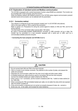
  • 1. 6. Control Functions and Parameter Settings 6-12 Explanation of standard serial and Modbus communication The VAT300 is equipped with a serial transmission function using RS485 as a standard. The inverter can be controlled with a host computer using this function. Either the Modbus network with Modbus protocol or the VAT300 series original communication protocol standard serial communication can be selected with the parameters. 6-12-1 Connection method This network is configured of one host computer (master) and 1 to 32 VAT300 units (slaves). CN2 on the basic section or TB3 is used for the connection. Refer to section 2-4. Precautions for wiring the control signal for details on CN2 and TB3, and for the wiring methods. The total length of the connected cable must be within 150 meters. By using a commercially-available RS485-RS232C converter or USB converter unit as a relay, the inverter can be connected to a host computer equipped with a serial port or USB, such as a commercially-available personal computer. • Connecting the host computer and VAT300 (1-on-1) Host computer RS232C RS485 VAT300 unit CN2 or TB3 Host computer USB RS485 VAT300 unit CN2 or TB3 DS1-1 Host computer RS232C RS485 VAT300 unit CN2 or TB3 DS1-1 RS485 USB/RS485 converter DS1-1 RS232C/RS485 converter CAUTION • Do not connect both CN2 and TB3 to the host computer. • CN2 is a 4-pole 4-core modular connector. Pay attention to the number of poles, and prepare the cable and connector. • Separates the communication cable from the main circuit cable and other power cables. • A shielded twisted pair cable should be used for connecting TB3 and the host computer. Connect the shielded twisted pair cable's shield to the TB3 SG. • When using a 1-on-1 connection, set the inverter's resistance (DS1 No. 1 switch on basic section) to the 120Ω side. • When connecting the TB3 and shielded twisted pair cable, do not solder the wires which are exposed after the sheath is peeled off. • If the communication is distorted and not carried out properly because of noise, etc., connect a ferrite core, etc., to the cable, and increase the noise resistance. 6 – 196
  • 2. 6. Control Functions and Parameter Settings When connecting several VAT300 units, connect two wires to each TB3 terminal, and couple the VAT300 units. An example of the connection is shown below. • Connecting the host computer and VAT300 (connecting several units) VAT300 unit VAT300 unit Host computer TB3TB3 VAT300 unit TB3 DS1-1 DS1-1 DS1-1 The details of the TB3 terminal section are shown below. SG D- D+ TB3 Shielded wire Shielded wire Shielded Shielded To host computer or inverter To next inverter CAUTION • Separates the communication cable from the main circuit cable and other power cables. • A shielded twisted pair wire should be used for connecting TB3 and the host computer. Connect the twisted pair cable's shield to the TB3 SG. • When using several slave units, set the resistance (DS1 No. 1 switch on basic section) of the last inverter to 120Ω. • When connecting the TB3 and shielded twisted pair cable, do not solder the wires which are exposed after the sheath is peeled off. • If the communication is distorted and not carried out properly because of noise, etc., connect a ferrite core, etc., to the cable, and increase the noise resistance. 6 – 197
  • 3. 6. Control Functions and Parameter Settings 6-12-2 Communication specifications Item Specification Connection method RS485, 2-wire type Transmission distance Total extension distance: 150m Baud rate Select from 1200, 2400, 4800, 9600, 14400, 19200, 38400bps Transmission method Start-stop synchronization, half-duplex communication Frame configuration Start : 1 bit Data : 8 bits Stop : Select from 1 bit or 2 bits Parity : Select from none, odd or even Error detection Sum check, parity, framing Transmission code 8-bit binary or ASCII Communication protocol Select from Modbus-RTU communication or standard serial communication Number of stations Set between 1 and 32 The factory settings are shown below. Communication protocol : Standard serial communication Baud rate : 9600bps Frame configuration : Start: 1bit, Data: 8bit, Stop: 2bit, Parity: odd, Station No.: 01 6-12-3 Procedures for enabling communication with host controller The communication parameters must be set to enable communication with the host controller. The procedure is given below. (1) Select C26-0, and select the communication method. Example: C26-0=0: Select standard serial communication. (2) Select the station No. Example: C26-2=18 (3) Set the baud rate. Example: C26-4=5: 38400bps (4) Set the number of stop bits. Example: C26-5=1: Stop bit 1 bit (5) Set the parity. Example: C26-6=1: No parity (6) After completing the settings, turn the power OFF once. When the control power has turned OFF, turn the power ON again. 6 – 198
  • 4. 6. Control Functions and Parameter Settings Communication with the set communication method is now possible. An excerpt of the parameter C26 setting details is given below. No. Parameter Unit Default Min. Max. Function C26 – Standard serial transmission setting 0 Function selection 0. 0. 1. 0: Standard serial 1: Modbus 1 Parameter change protection 1. 1. 5. The parameters with a  mark below can be changed. 2 Station No. 1. 0. 247. Set the local station No. 3 Response timer sec. 0.00 0.00 2.00 Set the minimum time from receiving command to returning an answer. 4 CN2 standard serial communication baud rate setting bps 2. 1. 7. =1: 4800 =2: 9600 =3: 14400 =4: 19200 =5: 38400 =6: 1200bps =7: 2400bps =6, 7 can be set from D21-3=9458.2 and above. 5 CN2 standard serial communication stop bit setting 2. 1. 2. =1: 1 bit =2: 2 bit 6 CN2 standard serial communication parity setting 3. 1. 3. =1: None =2: Even =3: Odd 7 Base section serial communication frequency (speed) unit setting 0. 0. 5. =0: 0.01Hz or 0.1min-1 unit: signed =1: 0.1Hz or 1min-1 unit: signed =2: 0.01% unit: signed =3: 0.01Hz or 0.1min-1 unit: unsigned =4: 0.1Hz or 1min-1 unit: unsigned =5: 0.01% unit: unsigned 6-12-4 Using the VAT300 Series dedicated communication (standard serial communication) The following exchanges can be carried out with the host computer by using the VAT300 series dedicated communication protocol (hereinafter, standard serial communication). (1) Reading and writing of Block-A, B, C, U parameters (2) Reading of Block-D monitor parameters (3) Reading and writing of sequence commands (4) Reading and writing of frequency commands and speed commands (5) Reading and writing of torque commands, torque bias 1 settings, drive torque limiter reduction settings, regenerative torque limiter reduction settings (6) Reading of fault history 6 – 199 Set- ting value Block A Para- meter Block B, C Parameter Basic Extend S/W H/W 1      2 × × × × × 3  × × × × 4  ×  × × 5  ×   × : Changeable ×: Unchangeable
  • 5. 6. Control Functions and Parameter Settings 6-12-4-a. Setting the standard serial transmission function (1) When executing setting data write (FW) from the host computer and operating, make sure that the sequence command CFS is ON, and that the various setting input point selection C02 is fixed to serial. Example) 1) Operation mode : Remote (RMT) Speed setting input point selection: C02-0=4 (sequence) CFS command : C04-1=4 (controlled with terminal block input PSI4), or 2) Speed setting input point selection: C02-0=2 (serial fixed) The details of the setting data are determined by the control mode selection (C30-0: f0) and FW command data No. Refer to section 6-12-4-g Setting data write (FW) for details. (2) When executing sequence command write (CW) from the host computer and operating, make sure that the sequence command COP is ON. Example) Operation mode : Remote (RMT) COP command : C03-8 = 16 (The inverter is always run with the sequence commands from the host computer.) Refer to section 6-12-4-i Sequence command write (CW) for details on the CW command. Refer to section 5-5 Sequence input logic Fig. 5-5 for details on the sequence input logic. Note) When sending the auxiliary operation sequence command in Fig. 5-5, make sure that control switchover method (J2 setting) C00-6 is set to serial transmission input. Control switchover method (J2 setting): C00-6 = 2 (serial transmission input) (3) Set parameter change protection with C26-1. (4) Set the local station number with C26-2. (5) Set the response timer value with C26-3. The response timer is the timer which specifies the minimum time for the VAT300 to return the response packet after the host computer sends the command packet. CAUTION When setting the frequency/speed and controlling the sequence with serial transmission, the automatic start and restart after power failure functions may not operate correctly. This is caused by a difference in the power voltage operation and time for transmitting the command. 6 – 200
  • 6. 6. Control Functions and Parameter Settings 6-12-4-b. Transmission procedure The VAT300 constantly waits for a command from the host computer. When the VAT300 correctly receives a command from the host computer, it always returns a response as shown in Fig. 4.1. 6-12-4-c. Transmission format "(" "G" STN TEXT "&" SUM ")" CR (1) Data format: 8-bit ASCII (2) Packet size: Maximum 128 Bytes (3) Packet contents "(" : Head code (1 Byte) "G" : VAT300 designation code (1 Byte) STN : Station No. (2 Bytes) Example) Station 1 → "01" Input with a hexadecimal. TEXT : Text area "&" : Check sum judgment code (1 Byte) When not using the check sum, delete the check sum judgment code and check sum. SUM : Check sum (2 Bytes) ")" : Final code (1 Byte) CR : Carriage return (1 Byte) 6-12-4-d. Transmission rules (1) When there is a request from the host computer, the VAT300 checks the station No. given in the packet, and processes the request when it matches the local station No. If the station numbers do not match, the packet is ignored. (2) Any space codes (20Hex) in the packet sent from the host computer are ignored. Note that the check sum is calculated including the space codes. (Example) ( G 0 1 F R 0 0 0 0 & 8 E ) CR 6 – 201 VAT300Host computer Command Response Command Re s p o n s e 1 packet Maximum 128 Bytes (The space code is ignored.) (The check sum, including the space code, is calculated.)
  • 7. 6. Control Functions and Parameter Settings (3) The check sum is always added to the response packet. The check sum can be omitted from the packet sent from the host computer, but the check sum is always added to the packet sent from the VAT300. (4) All transmission and reception data is 8-bit ASCII data. (5) All data input before "(" is input in the reception data is ignored. (6) Even if "(" is input while receiving the packet, the data received up to that point will be aborted. (Example) ( G –––––––––––––––––––– ( –––––––––––––––––––– (7) The reception is interpreted as done only when ")" CR is received. (8) Several commands can be arranged in one packet. (Up to nine commands.) In this case, "," is used as the delimiter between commands. If there are more than ten commands in one packet, error codes (illegal commands) equivalent to the number of excessive commands will be returned from the VAT300. Up to nine commands will be executed normally. An example of the command and response is shown below. (Example) Host computer transmission command packet ( G00FW00000001000 , FR0000 , CW0000000000040402 ) CR Response packet ( G00AK , FR00000001000 , AK & 0E ) Make sure that the command packet fits within 128 Bytes. Also make sure that the response packet in respect to the command packet is within 128 Bytes. (9) A broadcast packet can be sent. By setting the station No. to "FF", all VAT300 units in the transmission path will process the packet. The VAT300 will not send any response packet in respect to the broadcast packet. Thus, only write request commands are valid in the broadcast packet. (Example) ( G F F F W 0 0 0 0 0 0 0 0 4 0 4 ) CR 6 – 202 Even if "(" is input while receiving the packet, the data received up to that point will be aborted. (Ignored) (3rd command)(2nd command)(1st command) (delimiter)(delimiter) (Response to 3rd command) (Response to 2nd command) (Response to 1st command) (By setting the station No. to "FF", the broadcast packet will be received by all stations.)
  • 8. 6. Control Functions and Parameter Settings 6-12-4-e. Creating a check sum (Example) ( G 0 0 F R 0 0 0 0 & 4 D ) CR 28H 47H 30H 30H 46H 52H 30H 30H 30H 30H 26H The ASCII codes of the characters between "(" and "&" are added with hexadecimal, and the low-order byte of the obtained value is converted into an ASCII code and used for the check sum. 6 – 203 Add all 24DHEX Convert low-order 1 Byte to ASCII
  • 9. 6. Control Functions and Parameter Settings 6-12-4-f. Transmission commands Basic command format CMD (2 Byte) Data No. (4 Byte) DATA Command list Host computer to VAT300 CMD Data No. DATA Function FW 000n Nnnnnnn (7-digit decimal) Setting data write FR 000n None Setting data read CW 000n nn ······· nn (12-digit hexadecimal) Sequence command write CR 000n None Only sequence command read DW Annn Bnnn Cnnn Unnn Nnnnnn (6-digit decimal) Block-A, B, C, U parameter write DR Dnnn Annn Bnnn Cnnn Unnn None Block-D, A, B, C, U parameter read ER 000n None Fault history read Host computer from VAT300 CMD Data No. DATA Function FR 000n Nnnnnnn (7-digit decimal) Setting data read (response) CR 000n nn ······· nn (12-digit hexadecimal) Sequence command read (response) DR Dnnn Annn Bnnn Cnnn Unnn Nnnnnn (6-digit decimal) Block-D, A, B, C, U parameter read (response) ER 000n nn ······· nn (44-digit) Fault history read (response) AK None None Successful completion response in respect to write request command NK Error code nn (2 byte) None Error response in respect to command 6 – 204
  • 10. 6. Control Functions and Parameter Settings 6-12-4-g. Setting data write (FW) Function : The setting data is written to the selected setting register when the sequence command CFS is ON and the various setting input point selection: C02 is set to serial fixed. The contents of the setting data are determined by the control mode selection (C30-0: f0) and data No. Refer to Setting data table for the data No. Command F W 0 0 0 0 0 0 0 3 0 0 0 Response A K N K Error code (2 Byte) Setting data table Control mode DATA No. Name Unit Min. value Max. value V/f control C30-0 : f0 = 1 0 0 0 0 Frequency command Followin g C26-7 setting B00-4:Max. frequency setting (-) B00-4:Max. frequency setting Vector, PM control C30-0 : f0 = 2, 3, 4 0 0 0 0 Speed command B01-4:Max. speed setting (-) B01-4:Max. speed setting 0 0 0 0 Torque setting 0.1% -300.0 300.0 0 0 0 0 Torque bias 1 setting 0.1% -300.0 300.0 0 0 0 0 Drive torque limiter reduction setting 0.1% 0.0 100.0 0 0 0 0 Regenerative torque limiter reduction setting 0.1% 0.0 100.0 Coded data (Example) DATA – 0 0 0 1 2 3 (The data will be negative data when "-" is added.) The data can be set as negative data by adding "-" to the highest order digit of the DATA area. In the above example, the data is -123. Frequency command/speed command unit The unit for the frequency command/speed command can be changed with the C26-7: frequency (speed) unit setting. Refer to the 6-4: Parameter list or explanations. The default setting is C26-7=0: 0.01Hz or 0.1min-1 (signed) 6 – 205 (4-digit decimal data No. In this example, this is the "Frequency setting" write command.) (7-digit decimal setting value. In this example, 30.00Hz is set.) CMD DATA. No DATA (Successful completion) (Error response: Refer to Section 6. List of transmission error codes for details on the error codes.)
  • 11. 6. Control Functions and Parameter Settings 6-12-4-h. Setting data read (FR) Function : The setting value set with the FW command is read and returned. Command F R 0 0 0 1 Refer to section 6-12-5-g. Setting data write (FW) Setting data table for details on DATA No. Response F R 0 0 0 1 0 0 0 1 0 0 0 N K Error code (2 Byte) When the data to be read is coded For negative read data, a "-" is added to the highest order digit of the data. (Example) DATA – 0 0 0 1 2 3 (If a "-" is attached to the highest order digit, the data is a negative value.) In the above example, the data is -123. 6 – 206 (4-digit decimal data No. In this example, this is the "Torque setting" read command.) CMD DATA. No (4-digit decimal data No. The data No. from the host computer is returned.) (7-digit decimal read data. In this example, the data is 100.0%.) CMD DATA. No DATA (Error response: Refer to Section 6. List of transmission error codes for details on the error codes.)
  • 12. 6. Control Functions and Parameter Settings 6-12-4-i. Sequence command write (CW) Function : A sequence command is issued to the VAT300. The data sent at this time is held by the internal sequence command register until it is rewritten. To validate this sequence command, the sequence command: COP must be ON. Refer to section 6-12-5-a Setting the standard serial transmission function for details on setting COP. Command C W 0 0 0 0 0 0 0 A 0 0 0 5 Response A K N K Error code (2 Byte) 6-12-4-j. Sequence command read (CR) Function : The sequence command set with the CW command is read and returned. Command C R 0 0 0 1 Response C R 0 0 0 1 0 0 4 B 6 0 0 2 N K Error code (2 Byte) 6 – 207 (4-digit decimal. Refer to section 6- 12-5-o Sequence command bit assignment table for the numbers.) (8-digit hexadecimal setting value. In this example 000A0005h is set. * Refer to section 6-12-5-o Sequence command bit assignment table for details on the setting values. CMD DATA. No DATA1 DATA2 (Successful completion) (Error response: Refer to Section 6. List of transmission error codes for details on the error codes.) (4-digit decimal date No. Refer to section 6-12-5-o Sequence command bit assignment table for the numbers.) CMD DATA. No (Error code) (Error response: Refer to Section 6. List of transmission error codes for details on the error codes.) (4-digit decimal. The data No. from the host computer is returned.) (8-digit hexadecimal read data. In this example, 004B6002h is read.) * Refer to section 6-12-5-o Sequence command bit assignment table for details on the setting values. CMD DATA. No DATA1 DATA2
  • 13. 6. Control Functions and Parameter Settings 6-12-4-k. Block- A, B, C and U parameter write (DW) Function : The Block-A, B, C and U parameter data in the VAT300 unit is changed. Note that the parameter change protection may be set with C26-1. Parameters which cannot be changed during operation, cannot be changed during operation. Other parameters which cannot be changed during serial transmission are listed in the cautions. The data is configured from the list of constants without the decimal point. Example) A010 (Acceleration ramp time -1) 50.0 s → 000500 Command <Example: Block-A parameter setting> D W A 0 1 0 0 0 0 5 0 0 Response A K N K Error code (2 Byte) Setting data table DATA No. Name A n n n Block-A parameter B n n n Block-B parameter C n n n Block-C parameter U n n n Block-U parameter Sub No. Main No. CAUTION The parameters that cannot be changed with the write command are shown below. If the write command is executed for these parameters, an error will be returned (Parameter Read/Write Disable). • A04-0 to 7 (Custom constants) • C10-0 to 7 (Custom parameter selection) • A05-0 to 2 (Block-B, C parameter display skip) • C26-0 to 7 (Serial transmission setting) • B19-0 (Automatic tuning function) • Parameters not related to control mode selected with C30-0: f0. (Parameters that are not displayed on the operation panel.) Coded data The data can be set as negative data by adding "-" to the highest order digit of the DATA area. DATA – 0 0 1 2 3 6 – 208 (4-digit data No. In this example, this is A01-0: Acceleration ramp time -1.) (6-digit decimal setting value. In this example, 50.0 seconds is set.) CMD DATA. No DATA (Error response Refer to Section 6. List of transmission error codes for details on the error codes.) (Successful completion)
  • 14. 6. Control Functions and Parameter Settings 6-12-4-l. Block-A, B, C, U and D parameter read (DR) Function : The values of the block-A, B, C, U and D parameters in the VAT300 are read. Command <For monitor data read> D R A 0 3 0 Response D R A 0 3 0 0 0 0 0 5 0 N K Error code (2 Byte) Setting data table DATA No. Name D n n n Block-D parameter A n n n Block-A parameter B n n n Block-B parameter C n n n Block-C parameter U n n n Block-U parameter Sub No. Main No. CAUTION The parameters that cannot be read with the read command are shown below. If the read command is executed for these parameters, an error will be returned (Parameter Read/Write Disable). Refer to 6-12-4-n. List of transmission error codes for details on the error codes. • D20-0 (Fault history display) • D20-1 (Minor fault history display) • D20-2 (Parameter A, B, C change list) • D30-0 (Inverter type) • D30-1 (Option PCB) • D22-0 (Automatic tuning progress state) • A04-0 to 7 (Custom constants) • A05-0 to 2 (Block-B, C parameter skip) • C10-0 to 7 (Custom parameter selection) • Parameters not related to control mode selected with C30-0: f0. (Parameters that are not displayed on the operation panel.) If the data is coded data targeted for read, "-" will be attached to the highest-order digit of DATA. DATA – 0 0 1 2 3 6 – 209 (4-digit decimal data No. Refer to the previous setting data table for details on the numbers.) CMD DATA. No 4-digit data No. The data No. from the host computer is returned.) (6-digit decimal setting value. In this example, 50 is set.) CMD DATA. No DATA (Error response: Refer to Section 6. List of transmission error codes for details on the error codes.)
  • 15. 6. Control Functions and Parameter Settings 6-12-4-m. Fault history read (ER) Function : The fault history buffer of the VAT300 is read. Command E R 0 0 0 0 Response E R 0 0 0 0 ; 0 D 0 1 ; ・ ; 0 0 3 2 N K Error code (2 Byte) There are four fault history buffers from the latest to the 3rd to last fault histories. One group of these buffers is stored in the response. In one buffer, two fault causes, and the output frequency, output current, DC voltage, hardware fault signal, cumulative power ON time, and cumulative run time at the time of fault occurrence are stored. Refer to Appendix Table 4 for the fault cause display and details. Details of group (DATA) ; 0 3 0 4 ; 0 0 0 0 ; 0/– 0 0 0 0 0 ; 0 0 0 0 ; 0 3 0 4 ; 0 0 0 0 ; 0 0 0 0 0 ; 0 0 0 0 0 The above information is contained in the response data. A 43-byte data is sent. ";" is used to delimit each item in the group. Refer to Appendix 3 List of fault codes for details on the primary fault and secondary fault. The hardware fault signal displays the status of the D05-1: Hardware detection fault status bit as a 0 to FF hexadecimal. 6 – 210 4-digit data No. The data No. from the host computer is returned.) (Fault buffer corresponding to setting is displayed.) CMD DATA. No DATA Primary fault (4-digit hexadecimal) Secondary fault (4-digit hexadecimal) Output frequency (5-digit decimal + code) ) Output current (4-digit decimal) DC voltage (4-digit decimal) Hardware fault signal (4-digit hexadecimal) Cumulative power ON time (5-digit decimal) Cumulative run time (5-digit decimal) (Error response: Refer to Section 6. List of transmission error codes for details on the error codes.) (4-digit decimal data No. refer to the table on the right for details on the number.) CMD DATA. No DATA No.Explanation0000Latest fault history0000Previous fault history00002nd to last fault history00003rd to last fault history
  • 16. 6. Control Functions and Parameter Settings 6-12-4-n. List of transmission error codes The error codes added to the NK response in respect to a command from the host computer are shown below. Error code Error name Details 01 Transmission error A transmission error, such as parity error or overrun error, was detected. 02 Check sum error The check sum is illegal. 10 Illegal command The command is not defined. 11 Illegal parameter 1) The parameter does not exist, or 2) The transmission format does not match. 12 Illegal data 1) The data limit is exceeded, or 2) The format does not match. 13 Parameter protect The designated parameter is write-protected. (Write- protected with C26-1.) 14 Changing not possible during operation The designated parameter cannot be changed during operation. 15 Transmission/reception buffer overflow The transmission/reception data exceeds 128 Bytes. 16 Parameter read/write disable A read or write-prohibited parameter was accessed. 20 EEPROM BUSY The VAT300 is using the non-volatile memory. 6 – 211
  • 17. 6. Control Functions and Parameter Settings 6-12-4-o. Serial transmission sequence command Bit assignment table DATA No : 0 0 0 0 DATA1 AFS3 PROG Always 0 S0 S1 S2 S3 SE 15 14 13 12 11 10 9 8 7 6 5 4 3 2 1 0 Always 0 PICK AUXDV IVLM IBDW BUP Always 0 Always 0 DATA2 EMS RST FRUN RRUN FJOG RJOG EXC Always 0 15 14 13 12 11 10 9 8 7 6 5 4 3 2 1 0 AFS2 AFS1 CPASS IPASS CSEL Always 0 BRAKE HOLD DATA No : 0 0 0 1 DATA1 MBRK_ans PRST PIDEN S5 S6 S7 AUXSW0 AUXSW1 15 14 13 12 11 10 9 8 7 6 5 4 3 2 1 0 Always 0 Always 0 Always 0 Always 0 Always 0 OCL LV2 OCL LV1 PLS_IN DATA2 Always 0 ACR PCTL LIM1 LIM2 MCH RF0 DROOP 15 14 13 12 11 10 9 8 7 6 5 4 3 2 1 0 Always 0 Always 0 Always 0 Always 0 FPOS TRQB2 TRQB1 DEDB 6 – 212
  • 18. 6. Control Functions and Parameter Settings 6-12-5 Using Modbus communication The Modbus communication method is a single master/slave method. Only the master can start communication. The slave detects this communication, executes the designated function, and returns a response message. The master can communicate with the designated slave (station No.) and broadcast to all slaves. When using broadcast transmission, the slave only carries out the designated function and does not return a response message. The following exchanges can be made with the host computer by using this communication function. (1) Reading and writing of Block-A, B, C, U parameters (2) Reading of Block-D monitor parameters (3) Reading and writing of sequence commands (4) Reading and writing of frequency commands and speed commands (5) Reading and writing of torque commands, torque bias 1 settings, drive torque limiter reduction settings, regenerative torque limiter reduction settings (6) Reading of fault history (7) Reading of sequence status 6-12-5-a. Setting the Modbus communication function (1) When executing setting data write from the host computer and operating, make sure that the sequence command CFS is ON, and that the various setting input point selection C02 is fixed to serial. Example) 1) Operation mode : Remote (RMT) Speed setting input point selection: C02-0=4 (sequence) CFS command : C04-1=4 (controlled with terminal block input PSI4), or 2) Speed setting input point selection: C02-0=2 (serial fixed) The details of the setting data are determined by the control mode selection (C30-0: f0). Refer to 6- 12-5-f List of Modbus registers and setting examples for details. Refer to Fig. 5-9-1 to Fig. 5-9-8 for the sequence for selecting the determined setting data. (2) When executing sequence command write from the host computer and operating, make sure that the sequence command COP is ON. Example) Operation mode : Remote (RMT) COP command : C03-8 = 16 (The inverter is always run with the sequence commands from the host computer.) Refer to section 5-5 Sequence input logic Fig. 5-5 for details on the sequence input logic. Note) When sending the auxiliary operation sequence command in Fig. 5-5, make sure that control switchover method (J2 setting) C00-6 is set to serial transmission input. Control switchover method (J2 setting): C00-6 = 2 (serial transmission input) (3) Set parameter change protection with C26-1. (4) Set the local station number with C26-2. CAUTION When setting the frequency/speed and controlling the sequence with serial transmission, the automatic start and restart after power failure functions may not operate correctly. This is caused by a difference in the power voltage operation and time for transmitting the command. 6 – 213
  • 19. 6. Control Functions and Parameter Settings 6-12-5-b. Modbus protocol The VAT300 is compatible only with the Modbus compliant RTU mode. The communication protocol for the RTU mode is explained below. End/start Address Function Data CRC End/start Silent interval of 3.5 characters or more 8bit 8bit 8bit × n 16bit Silent interval of 3.5 characters or more Changeable with C26-3 Slave: 1 to 99 Broadcast: 0 Correspondence: 0x01, 0x02, 0x03, 0x08, 0x0F, 0x10, 0x17 Exception response: BIT7: ON Calculated for each command Changeable with C26-3 In the RTU mode, a silent interval of 3.5 characters or more (varies according to baud rate) is inserted at the start and end of transmission. The silent interval is a state in which data is not sent. Note that if C26- 3 is not equal to 0.00, the setting value will be followed. The slave side station No. is designated as Address. If a request is made from the slave side, the local station No. is set. The station No. is set with C26-2. The function executed by the slave is designated in Function and Data. Refer to the following explanations for details on the functions. CRC is an error check. Each is automatically calculated and set based on the details of Address to Data. The following calculation method is used. 1) CRC work = 0 × FFFF 2) CRC work low-order byte = CRC work low-order byte XOR send data (8-bit) 3) The following process is executed according to the state of the CRC work LSB. CRC work LSB Process 0 CRC work is shifted one bit to the right. MSB is set to 0 at this time. 1 CRC work is shifted one bit to the right. MSB is set to 0 at this time. The following operation is executed. CRC work = CRC work XOR 0xA001 4) The step 3) process is repeated for 8 bits (8 times). 5) The steps 2) to 4) are repeated for all send data (data from Address to before CRC). 6) The CRC work calculated with steps 1) to 5) is CRC. Example of command: 01 03 0002 0002 65CB (Send command: Read torque setting) CRC (Each is automatically calculated and set.) DATA1 (start register) Function Address (designates the station No. of the send destination slave) DATA2 (number of registers) 6 – 214
  • 20. 6. Control Functions and Parameter Settings CAUTION In the command example, a space is inserted to delimit each function. Do not insert the spaces when actually inputting the command. In the above command, input [01030002000265CB], and send. 6-12-5-c. VAT300 Modbus communication time chart The time chart for communication with the host computer is shown below. Silent interval VAT300 send data 1 (Addr, Func, Data, CRC) Silent interval Host computer side Silent interval VAT300 send data 1 (Addr, Func, Data, CRC) Silent interval VAT300 side The VAT300 judges the blocks of received data from the host side with the silent interval. The reception analysis process is started. After the data received from the host is analyzed, a response is sent. VAT300 send data 2 (Addr, Func, Data, CRC) Silent interval Received data analyze Silent interval Receive data The host computer waits for the silent interval time, and then sends one packet of data. When sending data continuously, the host computer waits for the silent interval again. The VAT300 recognizes the data sent after waiting the silent interval as the head of the packet, and starts the reception process. After the data is received, if a state in which no data is received for longer than the silent interval continues, the VAT300 determines that the reception is completed, judges and processes the contents of the command, and creates a request package. 6-12-5-d. Exceptional response code The VAT300 judges and processes the data based on the packet received from the host computer. If the data is illegal or if data exceeding the range is received, an exception response is returned to indicate that the process cannot be completed. The exceptional response is sent by setting bit7 of the sent function code to 1. The exception response code sent after the function code are shown below. List of exception response codes Code Name Occurrence conditions 01h Illegal function A function code, which is not listed, was set. 02h Illegal data address An address which does not exist was set. 03h Illegal data An error was found in the data setting. 04h IO data incorrect setting In the MUX data instruction, the set and input data exceeds the maximum value or minimum value. 05h MUX data corresponding No. not found In the MUX data instruction, the set and input parameter block No. or data No. does not exist. 06h MUX data incorrect setting In the MUX data instruction, the write data set with the multiplex data is an illegal data. 07h MUX data lock In the MUX data instruction, write or read was not possible. (Refer to CC-Link Function Specifications.) 0Bh Parameter function code incorrect A parameter function code which does not exist was set. 0Ch Outside input data range The written data exceeds the inverter setting range. 10h No corresponding parameter The read/write destination parameter was not found, or is set to "hide". 14h EEPROM busy Non-volatile memory is used. 6 – 215
  • 21. 6. Control Functions and Parameter Settings An example of the exception response sent from VAT300 is shown below. 01 83 02 C0F1 (Response: Replies that illegal data was accessed) CRC (Calculated on the INV side and automatically set.) Function (bit 7 turns ON) Exception response code (illegal data access) Addr (slave side station No.) CAUTION In the command example, a space is inserted to delimit each function. Do not insert the spaces when actually inputting the command. In the above example, the response is displayed as [018302C0F1]. 6-12-5-e. List of standard serial communication code correspondence The correspondence of the previous standard serial communication command and the Modbus functions is shown below. Function Start register: Function Standard serial communication command 01h Read Coil Status 0000 : Sequence command (input) 1 read 0020 : Sequence command (input) 2 read CR 02h Read Input Status Sequence status (output) read – 03h Read Holding Register 0000 : V/f Frequency setting read 0000 : VEC/PM Speed setting 0002 : VEC/PM Torque setting 0004 : VEC/PM Torque bias 1 setting 0006 : VEC/PM Drive torque limiter reduction setting 0008 : VEC/PM Regenerative torque limiter reduction setting FR 03E9 : Common Multiplexed data reading value – Fault information read 0063 : Read latest fault information 0073 : Read previous fault information 0083 : Read 2nd to last fault information 0093 : Read 3rd to last fault information 00A3 : Read latest minor fault information 00B3 : Read previous minor fault information 00C3 : Read 2nd to last minor fault information 00D3 : Read 3rd to last minor fault information ER 08h Diagnostic Self-diagnosis mode – 0Fh Force Multiple Coils 0000 : Sequence command (input) 1 write 0020 : Sequence command (input) 2 write CW 10h Preset Multiple Registers 0000 : V/f Frequency setting 0000 : VEC/PM Speed setting 0002 : VEC/PM Torque setting 0004 : VEC/PM Torque bias 1 setting 0006 : VEC/PM Drive torque limiter reduction setting 0008 : VEC/PM Regenerative torque limiter reduction setting FW Parameter write DW 03E7 : Common MUX command write for the multiplexed data reading value – 17h Read Multiple Registers Parameter read DR 6 – 216
  • 22. 6. Control Functions and Parameter Settings 6-12-5-f. List of Modbus registers and setting examples The details of each function and examples of setting the commands are given in the following section. ♦ Function 01h (Read Coil Status) Details of function Start register designation Number of registers Sequence command (Input) read 0000h : Sequence command 1 0020h : Sequence command 2 0020h (Sequence data 32 bit) Function : The sequence command (input) is read. This function carries out the same process as the CR command in the standard serial transmission function. Refer to section 6-12-4-o. Serial transmission sequence command bit assignment table for the layout of bits in the read command. Setting example: Modbus command setting example 01 01 0000 0020 3DD2 Command contents : The contents of the sequence command 1 are read. Response 01 01 04 00234167 7BA1 (Successful example) 01 81 02 C191 (Example of failure) CRC code Function Details of data Number of registers Start register Station No. Size (4byte) Function Station No. CRC code Exceptional response Function Station No. CRC code The correspondence of the read data contents and serial transmission sequence command's bit assignment table is shown below. Standard serial MODBUS (DATA No.) (Start register) Details of data 0000 → 0000 0001 → 0002 1003 5007 DATA 1 DATA 2 6 – 217
  • 23. 6. Control Functions and Parameter Settings ♦ Function 02h (Read input Status) Details of function Start register designation Number of registers Sequence status read 000h : Fixed 0040h (Sequence data 64 bit) Function : The sequence status is read. Refer to the bit assignment table on the next page for the layout of bits in the read command. Setting example: Modbus command setting example 01 02 0000 0040 79FA Command contents : The contents of the sequence status are read. Response 01 02 08 10035007 3827811F D37D (Successful example) 01 82 03 00A1 (Example of failure) Function Number of registers Start register Station No. CRC code Status data 2 Status data 1 Function Station No. Exceptional response Function Station No. CRC codeCRC code Size (8 byte) The contents of the read status data are as follow. 1003 5007 3827 811F Sequence status 3 Sequence status 1 Sequence status 0 Sequence status 2 Refer to the following table for the bit assignment of each status. 6 – 218
  • 24. 6. Control Functions and Parameter Settings Serial transmission sequence status bit assignment table Sequence status 0 ATN SPD1 SPD2 COP EC0 EC1 EC2 EC3 15 14 13 12 11 10 9 8 7 6 5 4 3 2 1 0 IDET REV LCL RDY2 RDY1 MC FLT RUN Sequence status 1 ULMT DVER MBRK Doff-End BPF RDELAY INT FAN Always 0 15 14 13 12 11 10 9 8 7 6 5 4 3 2 1 0 LLMT ZSP ASW FAN ALM AUXDV DCC ACC Sequence status 2 FPOS Always 0 Always 0 Always 0 Always 0 Always 0 Always 0 Always 0 15 14 13 12 11 10 9 8 7 6 5 4 3 2 1 0 PLC8 PLC7 PLC6 PLC5 PLC4 PLC3 PLC2 PLC1 Sequence status 3 Always 0 Always 0 Always 0 Always 0 Always 0 Always 0 Always 0 Always 0 15 14 13 12 11 10 9 8 7 6 5 4 3 2 1 0 MPO8 MPO7 MPO6 MPO5 MPO4 MPO3 MPO2 MPO1 6 – 219
  • 25. 6. Control Functions and Parameter Settings ♦ Function 03h (Read Holding Register) Control mode Details of function Start register Number of registers Unit Min. value Max. value V/f control Frequency setting 0000h 0002h (32-bit data) Following C26- 7 setting B00- 4:Max. frequency setting (-) B00-4:Max. frequency setting IM vector control PM motor control Speed setting 0000h 0002h (32-bit data) B01- 4:Max. speed setting (-) B01-4:Max. speed setting Torque setting 0002h 0002h (32-bit data) 0.1%/LSB -300.0 300.0 Torque bias 1 setting 0004h 0002h (32-bit data) 0.1%/LSB -300.0 300.0 Drive torque limiter reduction setting 0006h 0002h (32-bit data) 0.1%/LSB 0.0 100.0 Regenerative torque limiter reduction setting 0008h 0002h (32-bit data) 0.1%/LSB 0.0 100.0 Common Multiplexed data reading value 03E9h 0002h (32-bit data) Function : Frequency setting to Regenerative torque limiter reduction setting These functions carry out the same process as the FR command in the standard serial transmission function. Multiplexed data reading value This function reads the multiplexed data and is used when using a PLC without supporting Function17h. Refer to section 6-12-5-g. Setting example: Modbus command setting example 01 03 0002 0002 65CB Command contents : Torque setting value is read. Response 01 03 04 000003E8 FA8D (Successful example) 01 83 02 C0F1 (Example of failure) CRC code Function Data No. of registers Start register Station No. Size (4 Byte) Function Station No. CRC code Exceptional response Function Station No. CRC code Frequency command/speed command unit The unit for the frequency command/speed command can be changed with the C26-7: frequency (speed) unit setting. Refer to the 6-1: Parameter list or explanations. The default setting is C26-7=0: 0.01Hz or 0.1min-1 (signed) 6 – 220
  • 26. 6. Control Functions and Parameter Settings Details of function Start register Number of registers Fault history buffer Latest fault history 0063h 0010h Previous fault history 0073h 0010h 2nd to last fault history 0083h 0010h 3rd to last fault history 0093h 0010h Latest minor fault history 00A3h 0010h Previous minor fault history 00B3h 0010h 2nd to last minor fault history 00C3h 0010h 3rd to last minor fault history 00D3h 0010h Function : One block of the fault history is read. This function carries out the same process as the ER command in the standard serial transmission function. Refer to the following section for the contents read out. Setting example: Modbus command setting example 01 03 0063 0010 B418 Command contents : Torque setting value is read. Response 01 03 20 0000~0000 xxxx (Successful example) 01 83 02 C0F1 (Example of failure) Refer to the following section for the data contents. CRC code Function Data Number of registers Start register Station No. Size (32byte) Function Station No. CRC code Exceptional response Function Station No. CRC code The data is configured of 32 bytes. Each item is grouped in a 4-byte section. The details of the 4 bytes are shown below. (The values in the following table are a setting example.) 00000203 0000040D 000003E8 00000005F 0000013A 00000001 00000000 00000000 Primary fault details Secondary fault details Frequency value at fault Current value at fault DC voltage at fault Hardware fault signal Cumulative power ON time Cumulative run time 0.01Hz/LSB 0.1A/LSB 1V/LSB 1 hour/LSB 1 hour/LSB Refer to Appendix 3 Fault Codes for details on the primary fault and secondary fault. The hardware fault signal displays the status of the D05-1: Hardware detection fault status bit as a 0 to FF hexadecimal. 6 – 221
  • 27. 6. Control Functions and Parameter Settings ♦ Function 0Fh (Force Multiple Coils) Details of function Start register command Number of registers No. of bytes Sequence command (input) write 0000h : Sequence command 1 0020h : Sequence command 2 0020h (Sequence data 32 bit) 0004h Function : The sequence command is written. This function carries out the same process as the CW command in the standard serial transmission function. A 4byte command can be written in one command. Refer to section 6-12-4-o. Serial transmission sequence command bit assignment table for details on the bit assignment of the sequence command to be written in. Setting example: Modbus command setting example 01 0F 0000 0020 04 01234567 47C4 Command contents : The data contents are written to sequence command 1. Response 01 0F 20 3003 (Successful example) 01 8F 02 C5F1 (Example of failure) CRC code Function Number of registers Start register Station No. Response Data Function Station No. CRC code Exceptional response Function Station No. CRC code Data (4byte) Size The correspondence of the written sequence command bit assignment is shown below. Standard serial MODBUS (DATA No.) (Start register) Details of data 0000 → 0000 0001 → 0020 0123 4567 DATA 1 DATA 2 6 – 222
  • 28. 6. Control Functions and Parameter Settings ♦ Function 10h (Preset Multiple Registers) Control mode Details of function Start register Number of registers Number of bytes Unit Max. value Min. value V/f control Frequency setting 0000h 0002h (32-bit data) 04h Following C26-7 setting B00- 4:Max. frequency setting (-) B00-4:Max. frequency setting IM vector control PM motor control Speed setting 0000h 0002h (32-bit data) 04h B01- 4:Max. speed setting (-) B01-4:Max. speed setting Torque setting 0002h 0002h (32-bit data) 04h 0.1%/LSB -300.0 300.0 Torque bias 1 setting 0004h 0002h (32-bit data) 04h 0.1%/LSB -300.0 300.0 Drive torque limiter reduction setting 0006h 0002h (32-bit data) 04h 0.1%/LSB 0.0 100.0 Regenerative torque limiter reduction setting 0008h 0002h (32-bit data) 04h 0.1%/LSB 0.0 100.0 Function : A value is written into each setting. This function carries out the same process as the FW command in the standard serial transmission function. Setting example: Modbus command setting example 01 10 0000 0002 04 00001770 FDBB Command contents : The data value (60.00Hz) is written to the frequency setting. Response 01 10 00000002 41C8 (Successful example) 01 90 02 CDC1 (Example of failure) CRC code Function Number of registers Start register Station No. Response data Function Station No. CRC code Exceptional response Function Station No. CRC code Data (4byte) Size Frequency command/speed command unit The unit for the frequency command/speed command can be changed with the C26-7: frequency (speed) unit setting. Refer to the 6-1: Parameter list or explanations. The default setting is C26-7=0: 0.01Hz or 0.1min-1 (signed) Details of function Start register Number of Number 6 – 223
  • 29. 6. Control Functions and Parameter Settings designation registers of bytes Parameter write 03EBh 0003h (48 bit-data) 06h The parameter No. and parameter value are set in the data section. MUX command write 03E7h 0001h (16 bit-data) 02h The parameter No. value are set in the data section. Function : Parameter write A value is written to the parameter. This function carries out the same process as the DW command in the standard serial transmission function. MUX command write This function is used when using a PLC without supporting Function17h. Refer to section 6-12-5-g.. Setting example: Modbus command setting example 01 10 03EB 0003 06 A00000001388 8981 Command contents : The data value (50.00Hz) is written to parameter A00-0. Response 01 10 03EB 0003 F078(Successful example) 01 90 0B 0DC7 (Example of failure) CRC code Function Number of registers Start registers Station No. Response Data Function Station No. CRC code Exceptional response Function Station No. CRC code Data (8byte) Size Data setting (Byte): A000 00001388 Parameter designation section Data designation section Divide the parameter designation section as shown below and set the parameter No. 15 8 7 0 Block No. Data No.Function code 6 – 224 Function Function code Block-A parameter designation A Block-B parameter designation B Block-C parameter designation C Block-U parameter designation E
  • 30. 6. Control Functions and Parameter Settings ♦ Function 17h (Read Multiple Registers) Details of function Start register Number of registers No. of bytes Read parameter value 03E9h 0002h (32-bit data) – Read parameter No. setting 03E7h 0001h (16-bit data) 02h Function : The parameter contents are read. This process carries out the same process as the DR command in the standard serial transmission function. Setting example: Modbus command setting example 01 17 03E9 0002 03E7 0001 02 B004 9F52 Command contents : Parameter B00-4 is read. Response 01 17 04 00001388 F471 (Successful example) 01 97 10 4FFC (Example of failure) CRC code Function Number of registers Start register Station No. Size(4byte) Function Station No. CRC code Exceptional response Function Station No. CRC code Parameter No. Size Number of registers Start register Parameter data Divide the parameter designation section as shown below and set the parameter No. 15 8 7 0 Block No. Data No.Function code 6 – 225 Function Function code Monitor parameter designation D Block-A parameter designation A Block-B parameter designation B Block-C parameter designation C
  • 31. 6. Control Functions and Parameter Settings CAUTION The following parameters cannot be changed using Function 10h "setting data write". If the write command is used to the following parameters, the error should be found. A04-0 to 7 : Custom parameters A05-0 to 2 : Parameter B and C indicatory skip B19-0 : Automatic tuning selection C10-0 to 7 : Custom parameter register C26-0 to 7 : Standard serial transmission setting Parameters having no relation to the control mode selected by C30-0:f0 Parameters not displayed on the operation panel by setting A05-0 to 2. CAUTION The The following parameters cannot be read using Function 17h and Function 03h + 10h. D04-0 to 7 : Sequence status D05-0 to 1 : Minor fault monitor D07-0 : Pump operation status monitor D08-B : Sequence input terminal status display D08-C : Speed detection signal input status display D20-0 : Fault history monitor D20-1 : Minor failure past record indication D20-2 : Parameter A, B and C modification list entry D20-3 : Sequence input display (dedicated for LCD panel) D20-4 : Sequence output display (dedicated for LCD panel) D22-0 : Automatic tuning progression display D30-0 : Inverter type D30-1 : Option PCB D30-2 to 5 : Field network option failure monitor A04-0 to 7 : Custom parameters C10-0 to 7 : Custom parameter register However, the following parameters can be read by using other functions D04-0 to 3 (Sequence status-Input 1 to 4) : can be read by Function 01h D04-4 to 7 (Sequence status-Output 1 to 4): can be read by Function 02h D20-0 (Fault history monitor) : can be read by Function 03h D20-1 (Minor failure past record indication) : can be read by Function 03h 6 – 226
  • 32. 6. Control Functions and Parameter Settings 6-12-5-g. Additional function of Modbus The multiplexed data read through Function 17h can also be read by using Function 10h and 03h at the same time. Function Details of function Start register Number of registers No. of bytes 03h Multiplexed data reading value 03E9h 0002h (32-bit data) – 10h MUX command write for the multiplexed data reading value 03E7h 0001h (16-bit data) 02h In order to read parameters, follow the procedures below. 1) Set the parameter using Function 10h. 2) Set the parameter by using Function 03h, and the parameter setting can be read. Setting example: 1) Set the parameter using Function 10h. Modbus command setting example 01 10 03E7 0001 02 B015 3688 Command contents : Set the parameter B01-5. Response 01 10 03E70001 B1BA (Successful example) 01 90 03 0C01 (Example of failure) CRC code Function Number of registers Start register Station No. Function Station No. CRC code Exceptional response Function Station No. CRC code Parameter No. Size Response data The parameter setting method is the same as that of Function 10h and 17h (refer to the next page). 6 – 227
  • 33. 6. Control Functions and Parameter Settings 2) Set the parameter by using Function 03h, and the parameter setting can be read. Modbus command setting example 01 03 03E9 0002 15BB Command contents : Data read. Response 01 03 04 00000708 F9C5 (Successful example) 01 83 10 40FC (Example of failure) CRC code Function Number of registers Start register Station No. Function Station No. CRC code Exceptional response Function Station No. CRC code Response data Size(4byte) When the above procedure of 1) and 2) are correctly transferred, B01-5 will be shown in the response data column. This time the response data should be 00000708h=1800d (default of B01-5) Divide the parameter designation section as shown below and set the parameter No. 15 8 7 0 Block No. Data No.Function code 6 – 228 Function Function code Monitor parameter designation D Block-A parameter designation A Block-B parameter designation B Block-C parameter designation C