Download to read offline

![Page 2 of 55
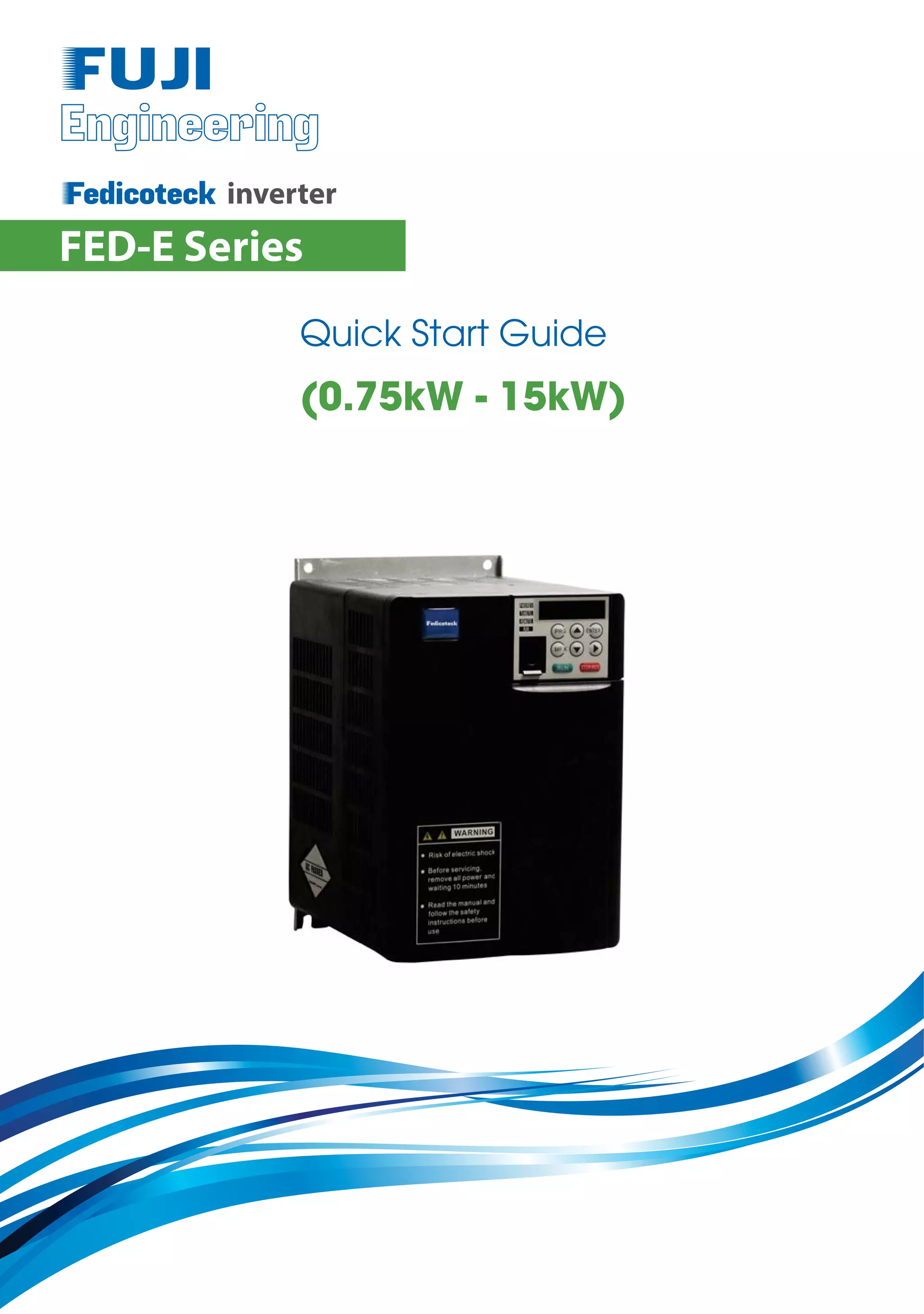
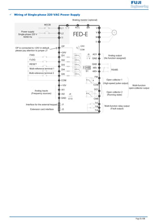
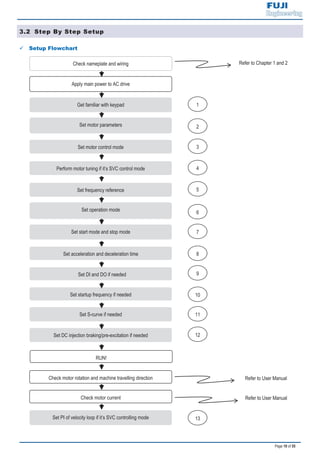
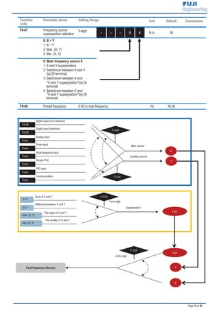
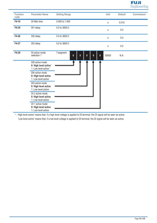
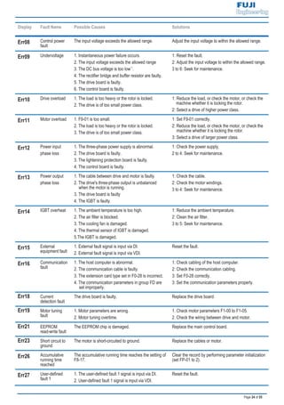
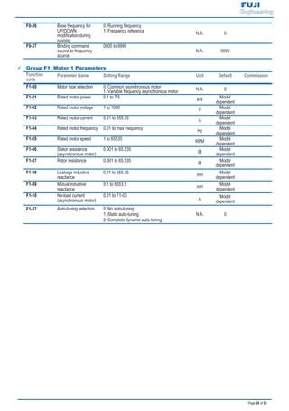
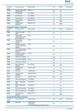
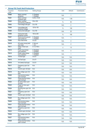
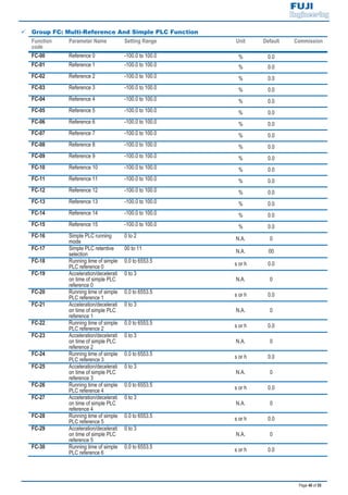
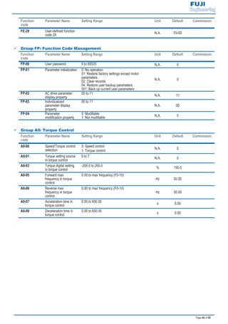
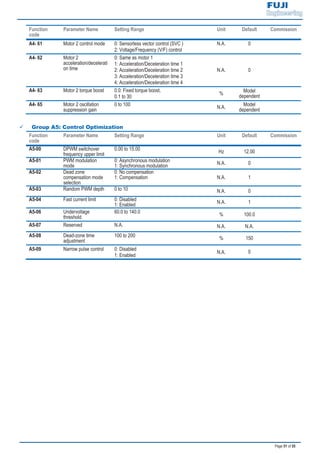
1.3 General Specifications
: At 6 kHz carrier frequency without derating.
: The mounting dimensions are shown below.
FEW/RED
A
W
B
H
D
FE
D/R
EWFE
D/R
EWLO
CA
LRU
N/E
RR
A
W
BH1
D
H
For models above 7.5 kW, the fan
is installed on the top of the AC
drive.
FE
D/R
EWFE
D/R
EWLO
CA
LRU
N/E
RR
Figure 1..Model of 0.4 to 2.2 kW Figure 2..Model of 3.7 to 15 kW
H [mm]
W [mm]
D [mm]
A [mm]
B [mm]
H1 [mm]
1.9 3.4 5.0 5.8 10.5 14.6 20.5 26.0 35.0
[kW] 0.4 0.75 1.5 2.2 3.7 5.5 7.5 11 15
[HP] 0.5 1 2 3 5 7.5 10 15 20
1.5 2.1 3.8 5.1 9.0 13.0 17.0 25.0 32.0
1.0 1.5 3.0 4.0 5.9 8.9 11.0 17.0 21.0
[kW] ≥ 0.15 ≥ 0.15 ≥ 0.15 ≥ 0.25 ≥ 0.30 ≥ 0.40 ≥ 0.50 ≥ 0.80 ≥ 1.00
[Ω] ≥ 300 ≥ 300 ≥ 220 ≥ 200 ≥ 130 ≥ 90 ≥ 65 ≥ 43 ≥ 32
Three-phase 380 to 440 VAC, -15% to 20% (323 to 528 VAC)
Three-phase 380 VAC (proportional to input voltage)
260 298
Mounting Hole Diameter [mm] 5 6
120% for 1 hour & 150% for 60 Sec &180% for 2 Sec
Max. Output Voltage
Dimension
DriveInput
Rated Input Voltage
Rated Input Current(A)
Rated Input Frequency 50/60 Hz, 5% (47.5 to 63 Hz)
128
Cooling Method Air Fan
108 130 140 180
96 108 122 160
158 164148 171 175.5
Max. Output Frequency 300 Hz for SVC control, 500 Hz for V/F control
Recommended
Braking Resistor
DriveOutput
Applicable
Motor
Output Current, [A]
Power Capacity, [kVA]
Overload Capacity
185 234 270
Frame Size
Voltage Class
Drive Model
1 4 5
Three-phase 380 VAC
2 3
118 198 248 284
/ 209](https://image.slidesharecdn.com/fed-e-quick-start-manual-bientanfuji-dienhathe-190409051519/85/Fed-e-quick-start-manual-bientanfuji-dienhathe-com-4-320.jpg)
![Page 3 of 55
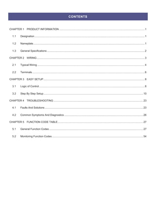
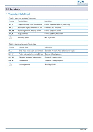
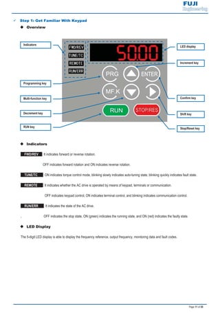
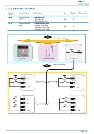
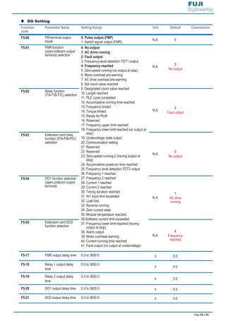
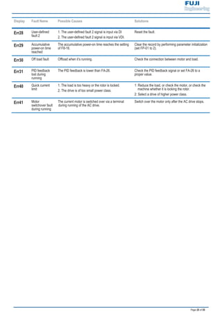
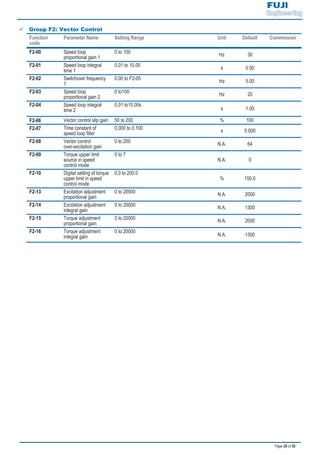
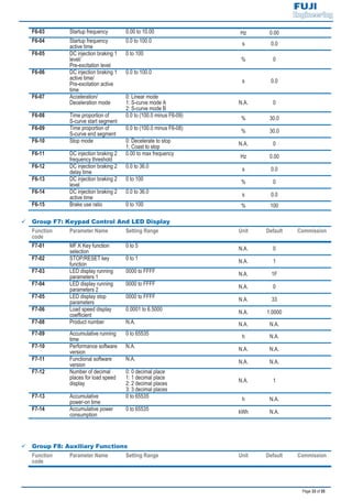
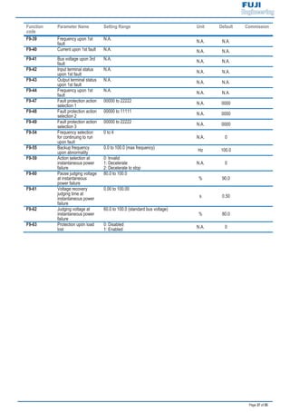
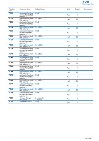
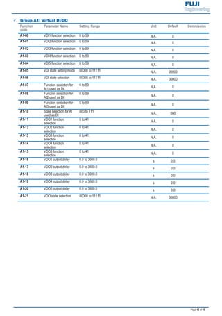
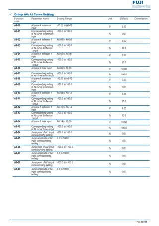
: Drives of 220 VAC power supply (both single-phase and three-phase) are being developed.
: At 6 kHz carrier frequency without derating.
: The mounting dimensions are shown below.
FEW/RED
A
W
B
H
D
FE
D/R
EWFE
D/R
EWLO
CA
LRU
N/E
RR
A
W
BH1
D
H
FE
D/R
EWFE
D/R
EWLO
CA
LRU
N/E
RR
Figure 3..Model of 0.4 to 2.2 kW Figure 4..Model of 3.7 to 7.5 kW
2 3 5
H [mm] 185 270
W [mm] 130 180
D [mm] 158 164 175.5
A [mm] 108 160
B [mm] 198 284
H1 [mm] 209 298
5.4 8.2 14.0 23.0 3.4 5.0 5.8 10.5 14.6 26.0 35.0
[kW] 0.4 0.75 1.5 2.2 0.4 0.75 1.5 2.2 3.7 5.5 7.5
[HP] 0.5 1 2 3 0.5 1 2 3 5 7.5 10
2.3 4.0 7.0 9.6 2.1 3.8 5.1 9.0 13.0 25.0 32
1.0 1.5 3.0 4.0 1.5 3.0 4.0 5.9 8.9 17.0 21.0
[kW] ≥ 0.08 ≥ 0.08 ≥ 0.10 / ≥ 0.15 ≥ 0.15 ≥ 0.25 ≥ 300 ≥ 0.40 ≥ 0.80 ≥ 1.00
[Ω] ≥ 200 ≥ 150 ≥ 100 / ≥ 150 ≥ 110 ≥ 100 ≥ 65 ≥ 45 ≥ 110 ≥ 100
148
Dimension
148
Voltage Class
Drive Model
Frame Size 1 2 1
300 Hz for SVC control, 500 Hz for V/F control
Mounting Hole Diameter [mm]
DriveInput
Rated Input Voltage
Rated Input Current(A)
Rated Input Frequency 50/60 Hz, 5% (47.5 to 63 Hz)
Recommended
Braking Resistor
Cooling Method Air Fan
Three-phase 220 VACSingle-phase 220 VAC
171
DriveOutput
Applicable
Motor
Output Current, [A]
Power Capacity, [kVA]
Overload Capacity 120% for 1 hour & 150% for 60 Sec &180% for 2 Sec
Max. Output Voltage Three-phase 220 VAC (proportional to input voltage)
Max. Output Frequency
Single-phase 220 VAC, -15 to 20%
(187 to 264 VAC)
Three-phase 220 VAC, -15 to 20%
(187 to 264 VAC)
4
/
128
5 Ø6
108
118
234
140
122
248
260
96
158](https://image.slidesharecdn.com/fed-e-quick-start-manual-bientanfuji-dienhathe-190409051519/85/Fed-e-quick-start-manual-bientanfuji-dienhathe-com-5-320.jpg)
![Page 8 of 55
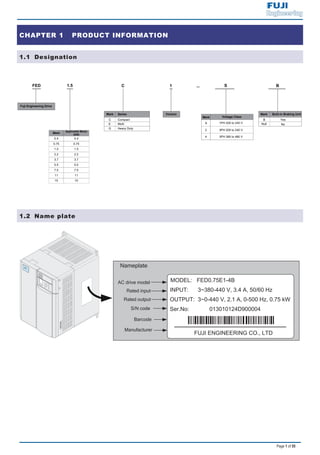
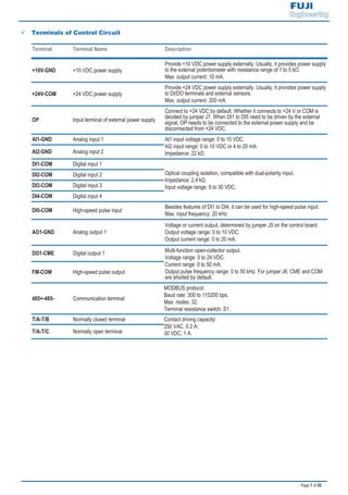
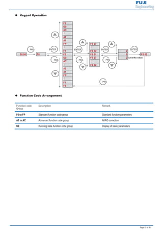
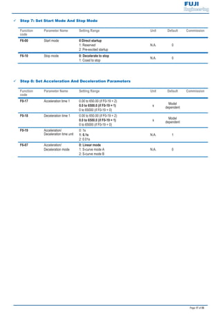
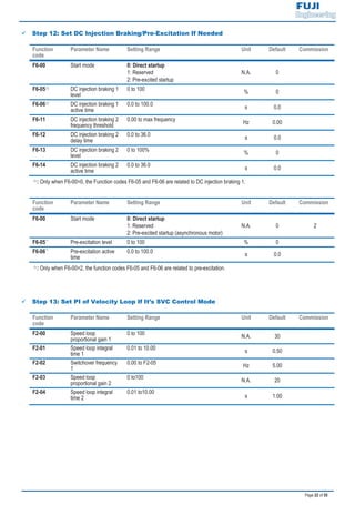
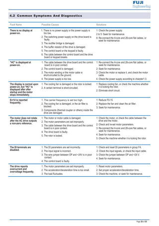
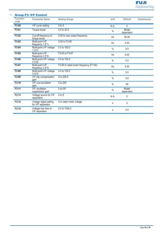
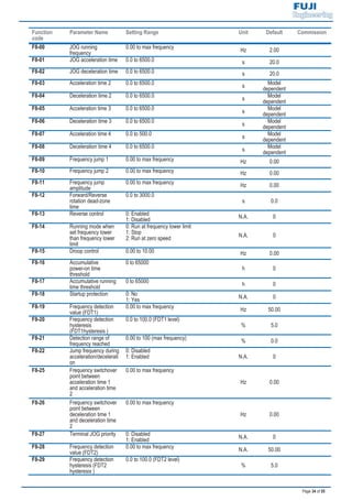
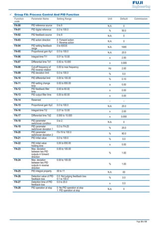
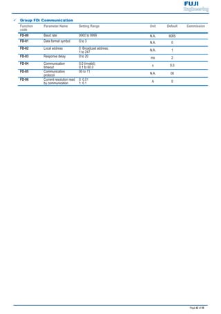
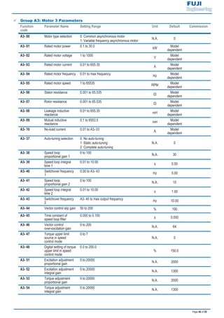
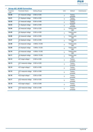
CHAPTER 3 EASY SETUP
3.1 Logic of Control
9 Complete Timing Diagram
F0-08
[x.x Hz]
F0-18
F0-17 F6-09 F6-08 [x.x Sec]
[x.x Sec] [x.x% ] [x.x% ]
F6-11
DC injection braking 2 frequency threshold
F6-04
[x.x Sec]
F6-03 F6-08 F6-09
[x.x Hz] [x.x% ] [x.x% ]
0
F6-06 [x.x Sec]: F6-13 [x%]: F6-14 [x.x Sec]:
DC injection braking 1 active time(if F6-00=0) DC injjection braking 2 level DC injection braking 2 active time
Pre-excitation active time (if F6-00=2)
F6-05 [x%]: F6-12 [x.x Sec] (default: 0.0 Sec)
DC injection braking 1 level (if F6-00=0) DC injection braking 2 delay time
Pre-excitation level (if F6-00=2)
t1
Time
DI 1 Forward
IGBT's Active
Frequency
Frequency
output
command
[ x.x Hz]: default 0.0 Hz
t9
ON
OFF
ON
OFF
t2 t4 t5 t6
t7
t8t3
0%
DC Injection/
Pre-excitation
Motor Current
20%
40%
Stages
100%
100%
50%
0%](https://image.slidesharecdn.com/fed-e-quick-start-manual-bientanfuji-dienhathe-190409051519/85/Fed-e-quick-start-manual-bientanfuji-dienhathe-com-10-320.jpg)

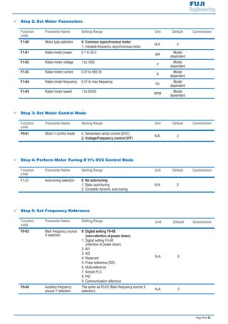
![Page 21 of 55
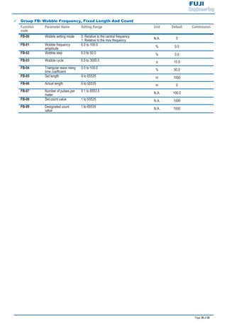
Function
code
Parameter Name Setting Range Unit Default Commission
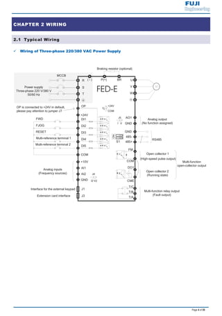
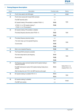
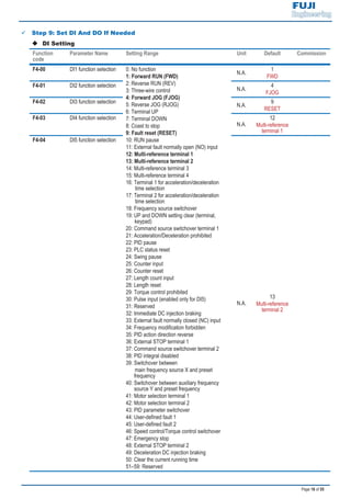
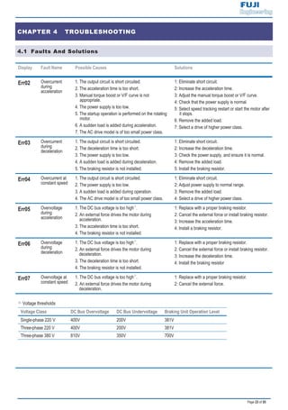
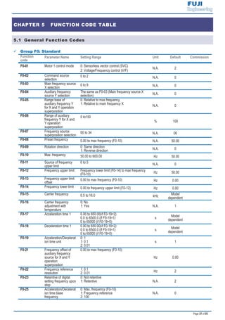
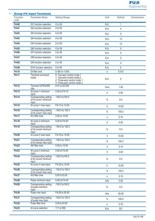
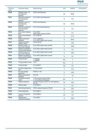
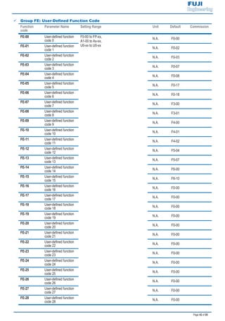
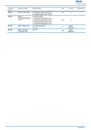
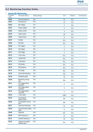
F5-22 DO active mode
selection
7-segment
0 0 0 0 0 N.A. 00000
DO2 active mode
0: Positive logic
1: Negative logic
DO1 active mode
0: Positive logic
1: Negative logic
Relay 2 active mode
0: Positive logic
1: Negative logic
Relay 1 active mode
0: Positive logic
1: Negative logic
FMR active mode
0: Positive logic
1: Negative logic
: ‘Positive logic’ means that, DO output terminal is normally the default state.
‘Negative logic’ means the opposite situation.
9 Step 10: Set Startup Frequency If Needed
Function
code
Parameter Name Setting Range Unit Default Commission
F6-03 Startup frequency 0.00 to 10.00 Hz 0.00
F6-04 Startup frequency
active time
0.0 to 100.0 s 0.0
9 Step 11: Set S-Curve If Needed
Function
code
Parameter Name Setting Range Unit Default Commission
F6-07 Acceleration/
Deceleration mode
0: Linear mode
1: S-curve mode A
2: S-curve mode B
N.A. 0 1
F6-08 Time proportion of
S-curve start segment
0.0 to [100.0 minus F6-09]
% 30.0
F6-09 Time proportion of
S-curve end segment
0.0 to [100.0 minus F6-08]
% 30.0](https://image.slidesharecdn.com/fed-e-quick-start-manual-bientanfuji-dienhathe-190409051519/85/Fed-e-quick-start-manual-bientanfuji-dienhathe-com-23-320.jpg)


This quick start guide provides instructions for setting up and operating an inverter. It begins with an overview of product information, including nameplate details and specifications. It then covers wiring, including diagrams for 3-phase and single-phase power supply types. Terminal functions are described for the main circuit and control circuit. The guide presents a timing diagram for the control logic and acceleration/deceleration profiles. It concludes with a step-by-step setup process, including getting familiar with the keypad, setting motor parameters, checking rotation direction, and setting function codes for features like the startup frequency and DC injection braking.


![[BoardgameVN] Luật chơi Mèo Nổ Expansion timebomb - Mở rộng 4](https://cdn.slidesharecdn.com/ss_thumbnails/expansiontimebomb-170817035147-thumbnail.jpg?width=640&height=640&fit=bounds)


