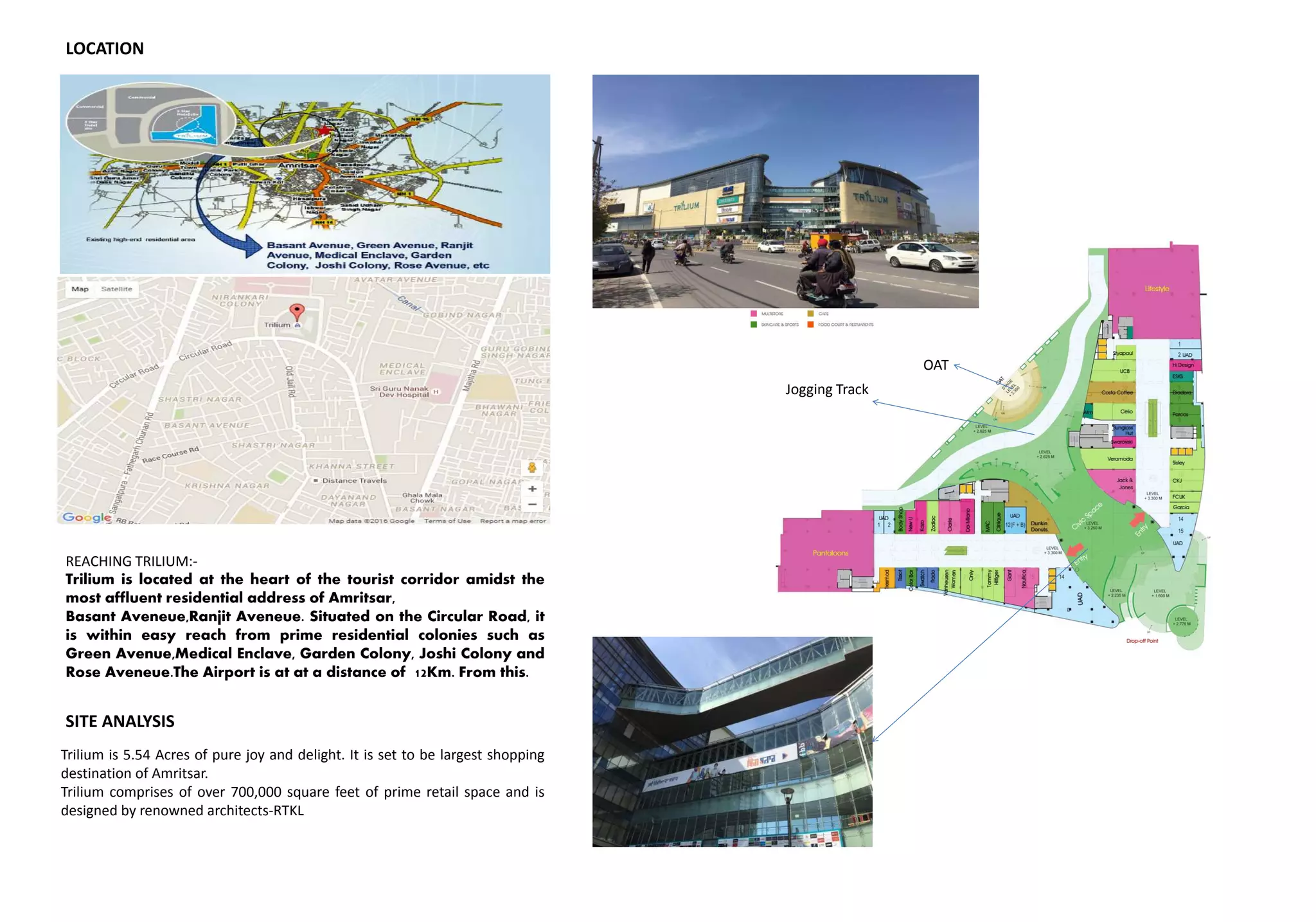
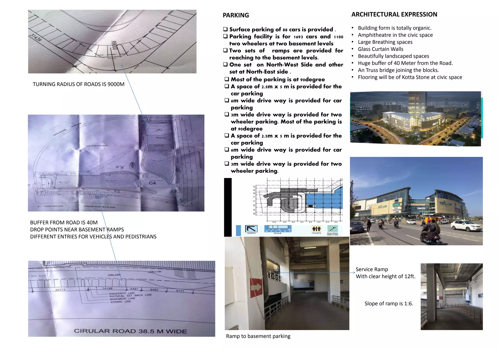
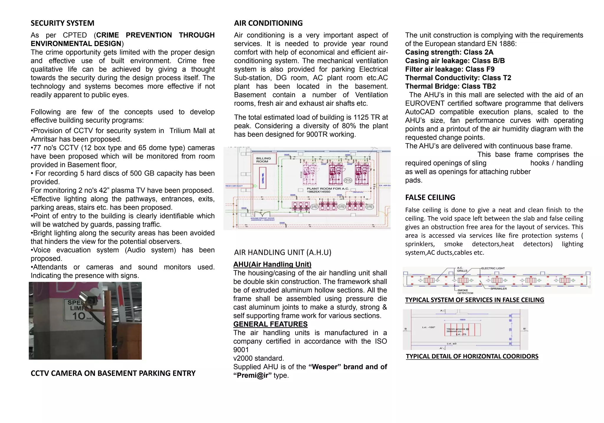
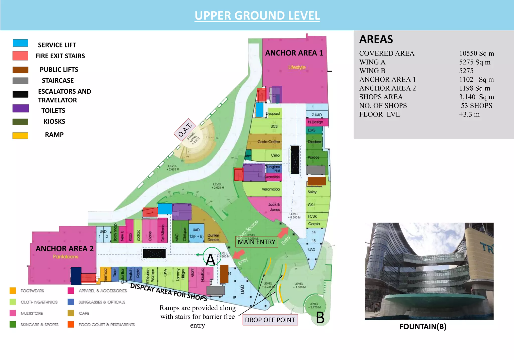
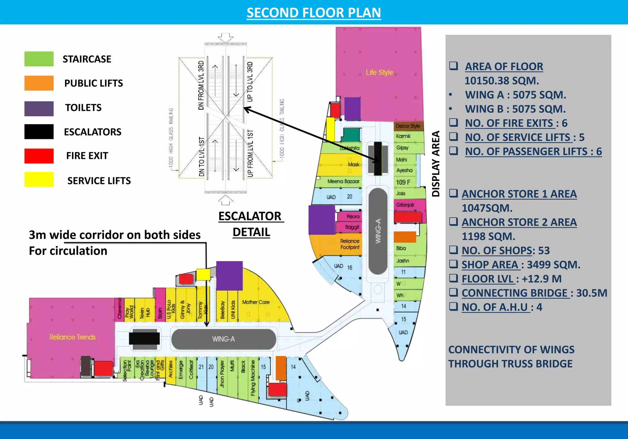
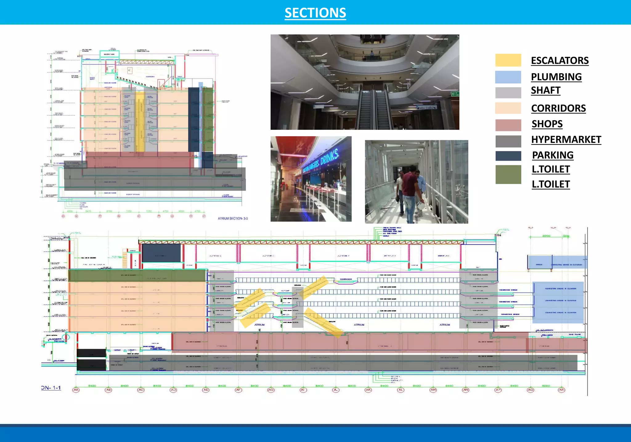
TRILIUM MALL CASE STUDY
SUBMITTED BY-
ANSHULA (042)
GUNJAN
KAENAT (55)
RAM GUPTA(069)
RIDHI(71)
YEEDIT DARDI(078)
SUBMITTED TO-
AR. PANKAJ CHHABRA
AR. HARWINDER KAUR
AR. BHANU
LOCATION
REACHING TRILIUM:-
Trilium is located at the heart of the tourist corridor amidst the
most affluent residential address of Amritsar,
Basant Aveneue,Ranjit Aveneue. Situated on the Circular Road, it
is within easy reach from prime residential colonies such as
Green Avenue,Medical Enclave, Garden Colony, Joshi Colony and
Rose Aveneue.The Airport is at at a distance of 12Km. From this.
SITE ANALYSIS
Trilium is 5.54 Acres of pure joy and delight. It is set to be largest shopping
destination of Amritsar.
Trilium comprises of over 700,000 square feet of prime retail space and is
designed by renowned architects-RTKL
Jogging Track
OAT
TURNING RADIUS OF ROADS IS 9000M
BUFFER FROM ROAD IS 40M
DROP POINTS NEAR BASEMENT RAMPS
DIFFERENT ENTRIES FOR VEHICLES AND PEDISTRIANS
PARKING
 Surface parking of 88 cars is provided .
 Parking facility is for 1693 cars and 1100
two wheelers at two basement levels
 Two sets of ramps are provided for
reaching to the basement levels.
 One set on North-West Side and other
set at North-East side .
 Most of the parking is at 90degree
 A space of 2.5m x 5 m is provided for the
car parking
 6m wide drive way is provided for car
parking
 3m wide drive way is provided for two
wheeler parking. Most of the parking is
at 90degree
 A space of 2.5m x 5 m is provided for the
car parking
 6m wide drive way is provided for car
parking
 3m wide drive way is provided for two
wheeler parking.
Ramp to basement parking
ARCHITECTURAL EXPRESSION
• Building form is totally organic.
• Amphitheatre in the civic space
• Large Breathing spaces
• Glass Curtain Walls
• Beautifully landscaped spaces
• Huge buffer of 40 Meter from the Road.
• An Truss bridge joining the blocks.
• Flooring will be of Kotta Stone at civic space
Service Ramp
With clear height of 12ft.
Slope of ramp is 1:6.
SERVICE BAY
 Service bays are at Lower Ground Floor.
 Rear entry is provided for the service
vehicles
 9 services bays are provided for smooth
loading and unloading.
 Width of each ramp is 6M.
SERVICE BAY
BARRIER FREE CONSIDERATIONS
• Two ramps each of width 6m and slope 1:12 are
provided at the North-West and North-East side.
• Both ramps reaches at the level of +3300m (3B+LG)
and transports the person directly to civic space.
• For further vertical circulation 6 lifts are provided for
physically challenged peoples.
• Width of the corridors is 5 metre which is sufficient for
their movement.
WATER SUPPLY DISTRIBUTION SYSTEM
Municipal water supply is connected to first
compartment of fire fighting tank, from where the
flow will be equalized through sleeves provided at
bottom of partition between two fire compartments &
then overflow into domestic compartment from
sleeves. This ensures that the fire compartment always
remains full.
• Area of Pump Room is 300 SQM.
• 8 underground water storage tanks are in this.
• 2 for fire fighting 2 for soft water 2 for domestic
water 2 for hard water
• Each tank is of 45000 Litres
• Underground rain water harvesting tanks are laid
in the space of buffer .
• Four Water harvesting tanks each of capacity of
30000 Litres.
• STP is near the pump room.
FIRE DETECTION SYSTEM IN UPPER GROUND
FLOOR
HOSE REEL
SPRINKLERSMOKE DETECTORS
SEWAGE TREATMENT PLANT
Sewage Treatment Plant is designed for capacity
equivalent to 80 % of estimated daily water demand .
Sewage treatment consist of primary, biological &
tertiary treatment.
Effluent from STP, as per outlet parameters is used for
landscape irrigation & HVAC make up water supply.
STP is compact, odor free, consuming minimum
electric power,
simple in O & M.
TREATED WATER STORAGE & PUMPING
Treated water after tertiary treatment is stored on a
recycle water tank.
Treated water is pumped for various purposes from
this tank as follows:
I.Submersible pumps including standby for
landscape irrigation.
RAIN WATER DISPOSAL & RAIN WATER
HARVESTING
•Rain water entering into the basements through ramps
etc is facilitated by Provision of channel drain with pre
cast RCC / CI gratings discharging in to Sumps at
suitable locations.
•Rain water from sumps are then be pumped to
Nearest storm drain at G.L. by providing submersible
dewatering pumps
•Rainwater from terraces shall be collected through
PVC rain water down take pipes At planned locations
which are connected to catch basins. However rain
water from open courtyards are collected through a
network of RCC & Collection chambers with desired
slopes, For rain water harvesting.
WATER TREATMENT
TANK
SECURITY SYSTEM
As per CPTED (CRIME PREVENTION THROUGH
ENVIRONMENTAL DESIGN)
The crime opportunity gets limited with the proper design
and effective use of built environment. Crime free
qualitative life can be achieved by giving a thought
towards the security during the design process itself. The
technology and systems becomes more effective if not
readily apparent to public eyes.
Following are few of the concepts used to develop
effective building security programs:
•Provision of CCTV for security system in Trilium Mall at
Amritsar has been proposed.
•77 no's CCTV (12 box type and 65 dome type) cameras
have been proposed which will be monitored from room
provided in Basement floor,
• For recording 5 hard discs of 500 GB capacity has been
provided.
For monitoring 2 no's 42” plasma TV have been proposed.
•Effective lighting along the pathways, entrances, exits,
parking areas, stairs etc. has been proposed.
•Point of entry to the building is clearly identifiable which
will be watched by guards, passing traffic.
•Bright lighting along the security areas has been avoided
that hinders the view for the potential observers.
•Voice evacuation system (Audio system) has been
proposed.
•Attendants or cameras and sound monitors used.
Indicating the presence with signs.
CCTV CAMERA ON BASEMENT PARKING ENTRY
AIR CONDITIONING
Air conditioning is a very important aspect of
services. It is needed to provide year round
comfort with help of economical and efficient air-
conditioning system. The mechanical ventilation
system is also provided for parking Electrical
Sub-station, DG room, AC plant room etc.AC
plant has been located in the basement.
Basement contain a number of Ventilation
rooms, fresh air and exhaust air shafts etc.
The total estimated load of building is 1125 TR at
peak. Considering a diversity of 80% the plant
has been designed for 900TR working.
AIR HANDLING UNIT (A.H.U)
AHU(Air Handling Unit)
The housing/casing of the air handling unit shall
be double skin construction. The framework shall
be of extruded aluminum hollow sections. All the
frame shall be assembled using pressure die
cast aluminum joints to make a sturdy, strong &
self supporting frame work for various sections.
GENERAL FEATURES
The air handling units is manufactured in a
company certified in accordance with the ISO
9001
v2000 standard.
Supplied AHU is of the “Wesper” brand and of
“Premi@ir” type.
The unit construction is complying with the requirements
of the European standard EN 1886:
Casing strength: Class 2A
Casing air leakage: Class B/B
Filter air leakage: Class F9
Thermal Conductivity: Class T2
Thermal Bridge: Class TB2
The AHU’s in this mall are selected with the aid of an
EUROVENT certified software programme that delivers
AutoCAD compatible execution plans, scaled to the
AHU’s size, fan performance curves with operating
points and a printout of the air humidity diagram with the
requested change points.
The AHU’s are delivered with continuous base frame.
This base frame comprises the
required openings of sling hooks / handling
as well as openings for attaching rubber
pads.
FALSE CEILING
False ceiling is done to give a neat and clean finish to the
ceiling. The void space left between the slab and false ceiling
gives an obstruction free area for the layout of services. This
area is accessed via services like fire protection systems (
sprinklers, smoke detectors,heat detectors) lighting
system,AC ducts,cables etc.
TYPICAL SYSTEM OF SERVICES IN FALSE CEILING
TYPICAL DETAIL OF HORIZONTAL COORIDORS
ELECTRIC SUPPLY
The electrical sub-stations in the basement where two
transformers of 2000KVA each have been placed with a
wall separating them to avoid fire hazards.For
uninterrupted power supply eight DG sets. 500 KVA
each. Hence a backup of 4000 KVA is supplied.
The overall electricity requirement of the Trilium is 3638
KW but the electricity supply from the authorities is of
4000 KVA, hence the requirement is met with the help
of generators I.e DG sets etc.
WIRING DIAGRAM
DIESEL GENERATOR SET
Capacity of DG sets is 500 KVA 8 no.s
o The scope of work comprises of designing
manufacturing, testing at work, packing, insurance,
storage at site, installation, testing and commissioning
of diesel generator set including its batteries, battery
charger, and AMF panels.
o Protection circuit oil tanks, exhaust pipes, grounding
of equipment with accessories and grounding of
neutral of generators and all electrical and mechanical
interlocking for safety, room acoustic arrangement for
generators installed with the room at site.
DESIGN PARAMETER
Voltage 415 V AC,
3 ph
& neutral
6.6 kV AC, 3 ph
Frequency 50 Hz
System earthing Effectively earthed
Maximum ambient
temperature 50°C
Location of set Lower basement.
Cooling of set Heat exchanger with cooling tower
Ventilation By exhaust fan
Gas exhaust By pipes drawn up to terrace and
Fixed at a certain height.
OIL TANK BURRIED UNDER THE GROUND
FOR DIESEL SUPPLY TO D.G. SETS
ANALYSIS
POSITIVE POINTS
 FAR AS PER THE NATIONAL BUILDING CODE.
 LARGE BREATHING SPACES.
 ENOUGH VERTICAL AND HORIZONTAL CIRCULATION AREAS.
 THE MALL HAS AN IMPRESSIVE EYE CATCHING VIEW.
 PROPER SEWAGE SYSTEM HAS BEEN DEVELOPED.
 100% POWER BACKUP.
 RAIN WATER HARVESTING TANKS HAVE BEEN PROVIDED.
 DIFFERENT ENTRIES FOR VEHICLES AND PEDISTRIANS.
 ENOUGH SPACE FOR SERVICE BAYS.
 SEPARATE ENTRY FOR BANQUET HALL
 WATER SUPPLY SYSTEM AS PER NBC.
 LARGE LANDSCAPED SPACES.
 ALL MODERN FACILITEIS HAVE BEEN PROVIDED.
 BARRIER FREE CONSIDERATIONS HAVE BEEN TAKEN IN TO ACCOUNT.
NEGATIVE POINTS
 NO DROP OFF POINT AT THE MAIN FAÇADE OF THE MALL.
 THE ENTRY OF THE PHYSICALLY CHALLENGED PERSONS IS AT THE BACKSIDE OF
THE MALL.
 THE ENTRY OF THE MALL IS AT LARGE DISTANCE FROM THE DROP OFF POINT.
 ROAD BUFFER IS ONLY AT ONE SIDE OF THE SITE.
DETAIL A
DETAIL B
 D.G SET AREA
3-DG SET 2000KVA
2-DG SET 1010 KVA
HT PANEL ROOM
TR-1 TO TR-5 HAVING
2200KVA
11KV/433 V ,LT PANEL
 PUMP ROOM
2 SOFT WATER TANK CAP
1,00,000 LITRES
2 RAW WATER TANKS CAP
1,00,000 LITRES
2 DOM WATER TANK CAP
1,00,000 LITRES
2 FIRE WATER TANK CAP
1,00,000 LITRES
BASEMENT - 1
DETAIL A
SERVICE LIFTS
FIRE EXIT
STAIR CASES
ESCALATORS AND
TRAVELATOR
TOILETS
STAIRCASE
PUBLIC LIFTS
DETAIL B
AREA OF FLOOR :
17584.695 SQ M.
SERVICES PROVIDED:
• DG SET AREA
• STP
• PUMPROOM
• AC PLANT ROOM
NO. OF FIRE EXITS : 6
NO. OF SERVICE LIFTS : 5
NO. OF PASSENGER LIFTS :
6
BASEMENT 1 FLOOR PLAN
AREAS
• COVERED AREA 16,925 Sq m
• 4-WHEELERS 501
• 2-WHEELERS 0
• FLOOR LVL 10.35 m
7m WIDE RAMP
SLOPE 1:10
EXIT RAMP
ENTRY RAMP
4-WHEELER
PARKING
EXIT RAMP
4M WIDE
ENTRY RAMP
4M WIDE
6MWIDEDRIVEWAY
6M WIDEDRIVEWAY
6M WIDEDRIVEWAY
6MWIDEDRIVEWAY
4-WHEELER
PARKING
4-WHEELER
PARKING
FIRE EXIT
STAIR CASES
SERVICE LIFT
ESCALATORS AND
TRAVELATOR
PARKING :
•BASEMENT PARKING IS PROVIDED FOR MALL.
BASEMENT - 2
• MOST OF THE PARKING IS AT 90 DEGREE
• A SPACE OF 2.5m X 5m IS PROVIDED FOR THE CAR
PARKING
• 6m WIDE DRIVE WAY IS PROVIDED FOR CAR
PARKING
• TWO SETS OF RAMPS ARE PROVIDED FOR
REACHING TO THE BASEMENT LEVELS.
• TWO WHEELER PARKING IS ONLY AT FIRST
BASEMENT, THIS BASEMENT IS ONLY FOR CAR
PARKING
PERMISSIBLE CONTROL NORM:
ACC TO PUDA BYE- LAWS
•FOR COMMERCIAL BUILDINGS ,E.C.S = 2)
ECS FOR BASEMENT PARKING IS 1ECS-32 SQ M
ECS FOR OPEN PARKING IS 1ECS -23 SQM
TOTAL COVERED AREA = XXXX SQ M
REQUIRED ECS AS PER ACHIEVED FAR = (COVERED
AREA X 2) /100 = (63509 X 2) /100 = 1270 ECS
AREA PROVIDED FOR PARKING =1270X 32SQM
=40,640SQM
AREA PROVIDED =41,200
STAIRCASE
PUBLIC LIFTS
RAMPS GOING DOWN TO FIRST BASEMENT
SERVICE ROAD
GARBAGE ROOM
UPPER PART OF AC PLANT
BANQUET HALL
SERVICE RAMP
GOING DOWN
LVL
-3.0 m
LVL
-3.0 m
BANQUET SERVICE
FIRE EXIT STAIRS
TOILETS
KIOSKS
ESCALATORS AND
TRAVELATOR
SERVICE LIFT
PUBLIC LIFTS
STAIRCASE
BANQUET HALL
HYPEMARKET
LOWER GROUND LEVEL
REQUIREMENT P R
PREFUNCTION AREA 260 Sqm -
BALL ROOM AREA 750 Sqm -
SPACE FOR LOOSE
FURNITURE 85 Sqm 75
Sqm
KITCHEN SPACE(35%) 265 Sqm 40%
STAFF DINNING 45 Sqm
TOILETS
LADIES P R
NO OF W.C PROVIDED 4 4
WASH BASINS 4 4
GENTS
NO OF WC PROVIDED 4 2
URINALS 4 8
WASH BASINS 4 4
*P-PROVIDED / R-REQUIRED AS PER NORMS
AREAS
TOTAL AREA -11593 Sqm
HYPERMART - 7896.729 Sqm
BANQUETHALL -2234.78 Sqm
BANQUET HALL AREA DETAIL
(AS PROVIDED)
MAIN ENTRY
DROP OFF POINT
ANCHOR AREA 2
A
B FOUNTAIN(B)
ANCHOR AREA 1
Ramps are provided along
with stairs for barrier free
entry
UPPER GROUND LEVEL
COVERED AREA 10550 Sq m
WING A 5275 Sq m
WING B 5275
ANCHOR AREA 1 1102 Sq m
ANCHOR AREA 2 1198 Sq m
SHOPS AREA 3,140 Sq m
NO. OF SHOPS 53 SHOPS
FLOOR LVL +3.3 m
AREAS
FIRE EXIT STAIRS
TOILETS
KIOSKS
ESCALATORS AND
TRAVELATOR
SERVICE LIFT
PUBLIC LIFTS
STAIRCASE
RAMP
FIRE EXIT STAIRS
TOILETS
ESCALATORS AND
TRAVELATOR
SERVICE LIFT
PUBLIC LIFTS
STAIRCASE
ESCALATORS
FOR 2ND LVL
ANCHOR AREA 1
3M WIDE CORRIDORANCHOR AREA 2
ESCALATORS
FOR UG LVL
DISPLAYAREA
TRUSS BRIDGE CONNECTING
TWO WINGS
3M WIDE CORRIDOR
ESCALATORS
FOR UG LVL
ESCALATORS
FOR 2ND FL
FIRST FLOOR
COVERED AREA 10550 Sq
m
WING A 5275 Sq m
WING B 5275 Sq m
ANCHOR AREA 1 1047 Sq m
ANCHOR AREA 2 1198 Sq m
SHOPS AREA 3,525 Sq
m
NO. OF SHOPS 53 SHOPS
FLOOR LVL +8.7 m
CONNECTING 30.5 m
BRIDGE
AREAS
SECOND FLOOR PLAN
3m wide corridor on both sides
For circulation
DISPLAYAREA
PUBLIC LIFTS
SERVICE LIFTS
FIRE EXIT
STAIRCASE
TOILETS
ESCALATORS
ESCALATOR
DETAIL
 AREA OF FLOOR
10150.38 SQM.
• WING A : 5075 SQM.
• WING B : 5075 SQM.
 NO. OF FIRE EXITS : 6
 NO. OF SERVICE LIFTS : 5
 NO. OF PASSENGER LIFTS : 6
 ANCHOR STORE 1 AREA
1047SQM.
 ANCHOR STORE 2 AREA
1198 SQM.
 NO. OF SHOPS: 53
 SHOP AREA : 3499 SQM.
 FLOOR LVL : +12.9 M
 CONNECTING BRIDGE : 30.5M
 NO. OF A.H.U : 4
CONNECTIVITY OF WINGS
THROUGH TRUSS BRIDGE
ESCALATORS
FOR 2ND LVL
ESCALATORS
FOR 4TH LVL
THIRD FLOOR PLAN
3m wide corridor on both sides
For circulation
DISPLAYAREA
PUBLIC LIFTS
SERVICE LIFTS
FIRE EXIT
STAIRCASE
TOILETS
ESCALATORS
 AREA OF FLOOR
10150.38 SQM.
• WING A : 5075 SQM.
• WING B : 5075 SQM.
 NO. OF FIRE EXITS : 6
 NO. OF SERVICE LIFTS : 5
 NO. OF PASSENGER LIFTS : 6
 ANCHOR STORE 1 AREA
1047SQM.
 ANCHOR STORE 2 AREA
1198 SQM.
 NO. OF SHOPS: 53
 SHOP AREA : 3499 SQM.
 FLOOR LVL : +17.1 M
 CONNECTING BRIDGE : 30.5M
 NO. OF A.H.U : 4
CONNECTIVITY OF WINGS
THROUGH TRUSS BRIDGE
FOURTH FLOOR PLAN
DISPLAYAREA
PUBLIC LIFTS
SERVICE LIFTS
FIRE EXIT
STAIRCASE
TOILETS
ESCALATORS
 AREA OF FLOOR
8072 SQM.
• WING A : 4037 SQM.
• WING B : 4037SQM.
 NO. OF FIRE EXITS : 6
 NO. OF SERVICE LIFTS : 5
 NO. OF PASSENGER LIFTS : 6
 ANCHOR STORE 1 AREA
1998.2 SQM.
 ANCHOR STORE 2 AREA
1198 SQM.
 NO. OF SHOPS: 34
 SHOP AREA : 3499 SQM.
 FLOOR LVL : +21.3 M
 CONNECTING BRIDGE : 30.5M
 NO. OF A.H.U : 4
ON THIS FLOOR WING A AND
WING B ARE NOT CONNECTED
ANCHOR AREA 1
FAMILY ENTERTAINMENT
CENTER
S
S’
B
E
ESCALATORS
FOR 3ND LVL
ESCALATORS
FOR 5TH LVL
ON THIS FLOOR WING-A AND WING-B IS
NOT CONNECTED.
FROM THIS FLOOR FIRE STAIRCASE S ENDS
AND A NEW STAIRCASE S’ IS CONNECTING
FIFTH FLOOR (SATYAM).
FROM THIS LEVEL ESCALATOR E IS MADE
CONNECTING WITH FIFTH FLOOR.
TRIPLE HEIGHT IS ACHIEVED AT PLACE B
WITH 14 M HIGH COLUMNS.
FIFTH FLOOR PLAN
DISPLAYAREA
PUBLIC LIFTS
SERVICE LIFTS
FIRE EXIT
STAIRCASE
TOILETS
ESCALATORS
 AREA OF FLOOR
8114 SQM.
• WING A : 4057 SQM.
• WING B : 4057SQM.
 NO. OF FIRE EXITS : 6
 NO. OF SERVICE LIFTS : 5
 NO. OF PASSENGER LIFTS : 6
 NO. OF RESTAURANTS : 3
 FOOD COURT AREA
935 SQM.
 NO. OF KIOSKS : 12
 SHOP AREA : 3504 SQM.
 FOOD KIOSK AREA :
935 SQM.
 FLOOR LVL : +25.5 M
 CONNECTING BRIDGE : 30.5M
 NO. OF A.H.U : 4
ESCALATORS
FOR 6TH LVL
LEVELS
LOBBY AREA LVL = 25.5m
CORRIDOR LVL = 25.5m
PROJECTOR AREA LVL=+31.5mCOOLING TOWERS
OF D.G.AND A.C.
TERRACE
HAS 8
A.H.Us
FOR
CINEPLEX
MACHINE ROOMTRUSS ROOF AUDITORIUM
A.H.U MACHINES
INSTALLED ON 5th
FLOOR TERRACE LEVEL
AUDITORIUM ( AT FOYER LEVEL )
ENTRY RAMPS
FIRE EXIT STAIR CASES
ENTRY FOYER
TOILETS
MACHINE ROOM STAFF AREA
CAFETERIASKY LOUNGE
AUDITORIUM ( AT PROJECTOR LEVEL )
PROJECTOR ROOM CORRIDOR
PROJECTOR
ROOM
WINDOW
LVL +31.5
m
MULTI TRUSS
AT TOP
PROJECTOR ROOM CORRIDOR
FIRE EXIT STAIR CASES
MACHINE ROOM
PROJECTOR
ROOM
WINDOW
SECTIONS
ESCALATORS
PLUMBING
SHAFT
CORRIDORS
SHOPS
HYPERMARKET
PARKING
L.TOILET
L.TOILET

Case study trilium MALL AMRITSAR

  • 1.
    TRILIUM MALL CASESTUDY SUBMITTED BY- ANSHULA (042) GUNJAN KAENAT (55) RAM GUPTA(069) RIDHI(71) YEEDIT DARDI(078) SUBMITTED TO- AR. PANKAJ CHHABRA AR. HARWINDER KAUR AR. BHANU
  • 2.
    LOCATION REACHING TRILIUM:- Trilium islocated at the heart of the tourist corridor amidst the most affluent residential address of Amritsar, Basant Aveneue,Ranjit Aveneue. Situated on the Circular Road, it is within easy reach from prime residential colonies such as Green Avenue,Medical Enclave, Garden Colony, Joshi Colony and Rose Aveneue.The Airport is at at a distance of 12Km. From this. SITE ANALYSIS Trilium is 5.54 Acres of pure joy and delight. It is set to be largest shopping destination of Amritsar. Trilium comprises of over 700,000 square feet of prime retail space and is designed by renowned architects-RTKL Jogging Track OAT
  • 3.
    TURNING RADIUS OFROADS IS 9000M BUFFER FROM ROAD IS 40M DROP POINTS NEAR BASEMENT RAMPS DIFFERENT ENTRIES FOR VEHICLES AND PEDISTRIANS PARKING  Surface parking of 88 cars is provided .  Parking facility is for 1693 cars and 1100 two wheelers at two basement levels  Two sets of ramps are provided for reaching to the basement levels.  One set on North-West Side and other set at North-East side .  Most of the parking is at 90degree  A space of 2.5m x 5 m is provided for the car parking  6m wide drive way is provided for car parking  3m wide drive way is provided for two wheeler parking. Most of the parking is at 90degree  A space of 2.5m x 5 m is provided for the car parking  6m wide drive way is provided for car parking  3m wide drive way is provided for two wheeler parking. Ramp to basement parking ARCHITECTURAL EXPRESSION • Building form is totally organic. • Amphitheatre in the civic space • Large Breathing spaces • Glass Curtain Walls • Beautifully landscaped spaces • Huge buffer of 40 Meter from the Road. • An Truss bridge joining the blocks. • Flooring will be of Kotta Stone at civic space Service Ramp With clear height of 12ft. Slope of ramp is 1:6.
  • 4.
    SERVICE BAY  Servicebays are at Lower Ground Floor.  Rear entry is provided for the service vehicles  9 services bays are provided for smooth loading and unloading.  Width of each ramp is 6M. SERVICE BAY BARRIER FREE CONSIDERATIONS • Two ramps each of width 6m and slope 1:12 are provided at the North-West and North-East side. • Both ramps reaches at the level of +3300m (3B+LG) and transports the person directly to civic space. • For further vertical circulation 6 lifts are provided for physically challenged peoples. • Width of the corridors is 5 metre which is sufficient for their movement. WATER SUPPLY DISTRIBUTION SYSTEM Municipal water supply is connected to first compartment of fire fighting tank, from where the flow will be equalized through sleeves provided at bottom of partition between two fire compartments & then overflow into domestic compartment from sleeves. This ensures that the fire compartment always remains full. • Area of Pump Room is 300 SQM. • 8 underground water storage tanks are in this. • 2 for fire fighting 2 for soft water 2 for domestic water 2 for hard water • Each tank is of 45000 Litres • Underground rain water harvesting tanks are laid in the space of buffer . • Four Water harvesting tanks each of capacity of 30000 Litres. • STP is near the pump room. FIRE DETECTION SYSTEM IN UPPER GROUND FLOOR HOSE REEL SPRINKLERSMOKE DETECTORS SEWAGE TREATMENT PLANT Sewage Treatment Plant is designed for capacity equivalent to 80 % of estimated daily water demand . Sewage treatment consist of primary, biological & tertiary treatment. Effluent from STP, as per outlet parameters is used for landscape irrigation & HVAC make up water supply. STP is compact, odor free, consuming minimum electric power, simple in O & M. TREATED WATER STORAGE & PUMPING Treated water after tertiary treatment is stored on a recycle water tank. Treated water is pumped for various purposes from this tank as follows: I.Submersible pumps including standby for landscape irrigation. RAIN WATER DISPOSAL & RAIN WATER HARVESTING •Rain water entering into the basements through ramps etc is facilitated by Provision of channel drain with pre cast RCC / CI gratings discharging in to Sumps at suitable locations. •Rain water from sumps are then be pumped to Nearest storm drain at G.L. by providing submersible dewatering pumps •Rainwater from terraces shall be collected through PVC rain water down take pipes At planned locations which are connected to catch basins. However rain water from open courtyards are collected through a network of RCC & Collection chambers with desired slopes, For rain water harvesting. WATER TREATMENT TANK
  • 5.
    SECURITY SYSTEM As perCPTED (CRIME PREVENTION THROUGH ENVIRONMENTAL DESIGN) The crime opportunity gets limited with the proper design and effective use of built environment. Crime free qualitative life can be achieved by giving a thought towards the security during the design process itself. The technology and systems becomes more effective if not readily apparent to public eyes. Following are few of the concepts used to develop effective building security programs: •Provision of CCTV for security system in Trilium Mall at Amritsar has been proposed. •77 no's CCTV (12 box type and 65 dome type) cameras have been proposed which will be monitored from room provided in Basement floor, • For recording 5 hard discs of 500 GB capacity has been provided. For monitoring 2 no's 42” plasma TV have been proposed. •Effective lighting along the pathways, entrances, exits, parking areas, stairs etc. has been proposed. •Point of entry to the building is clearly identifiable which will be watched by guards, passing traffic. •Bright lighting along the security areas has been avoided that hinders the view for the potential observers. •Voice evacuation system (Audio system) has been proposed. •Attendants or cameras and sound monitors used. Indicating the presence with signs. CCTV CAMERA ON BASEMENT PARKING ENTRY AIR CONDITIONING Air conditioning is a very important aspect of services. It is needed to provide year round comfort with help of economical and efficient air- conditioning system. The mechanical ventilation system is also provided for parking Electrical Sub-station, DG room, AC plant room etc.AC plant has been located in the basement. Basement contain a number of Ventilation rooms, fresh air and exhaust air shafts etc. The total estimated load of building is 1125 TR at peak. Considering a diversity of 80% the plant has been designed for 900TR working. AIR HANDLING UNIT (A.H.U) AHU(Air Handling Unit) The housing/casing of the air handling unit shall be double skin construction. The framework shall be of extruded aluminum hollow sections. All the frame shall be assembled using pressure die cast aluminum joints to make a sturdy, strong & self supporting frame work for various sections. GENERAL FEATURES The air handling units is manufactured in a company certified in accordance with the ISO 9001 v2000 standard. Supplied AHU is of the “Wesper” brand and of “Premi@ir” type. The unit construction is complying with the requirements of the European standard EN 1886: Casing strength: Class 2A Casing air leakage: Class B/B Filter air leakage: Class F9 Thermal Conductivity: Class T2 Thermal Bridge: Class TB2 The AHU’s in this mall are selected with the aid of an EUROVENT certified software programme that delivers AutoCAD compatible execution plans, scaled to the AHU’s size, fan performance curves with operating points and a printout of the air humidity diagram with the requested change points. The AHU’s are delivered with continuous base frame. This base frame comprises the required openings of sling hooks / handling as well as openings for attaching rubber pads. FALSE CEILING False ceiling is done to give a neat and clean finish to the ceiling. The void space left between the slab and false ceiling gives an obstruction free area for the layout of services. This area is accessed via services like fire protection systems ( sprinklers, smoke detectors,heat detectors) lighting system,AC ducts,cables etc. TYPICAL SYSTEM OF SERVICES IN FALSE CEILING TYPICAL DETAIL OF HORIZONTAL COORIDORS
  • 6.
    ELECTRIC SUPPLY The electricalsub-stations in the basement where two transformers of 2000KVA each have been placed with a wall separating them to avoid fire hazards.For uninterrupted power supply eight DG sets. 500 KVA each. Hence a backup of 4000 KVA is supplied. The overall electricity requirement of the Trilium is 3638 KW but the electricity supply from the authorities is of 4000 KVA, hence the requirement is met with the help of generators I.e DG sets etc. WIRING DIAGRAM DIESEL GENERATOR SET Capacity of DG sets is 500 KVA 8 no.s o The scope of work comprises of designing manufacturing, testing at work, packing, insurance, storage at site, installation, testing and commissioning of diesel generator set including its batteries, battery charger, and AMF panels. o Protection circuit oil tanks, exhaust pipes, grounding of equipment with accessories and grounding of neutral of generators and all electrical and mechanical interlocking for safety, room acoustic arrangement for generators installed with the room at site. DESIGN PARAMETER Voltage 415 V AC, 3 ph & neutral 6.6 kV AC, 3 ph Frequency 50 Hz System earthing Effectively earthed Maximum ambient temperature 50°C Location of set Lower basement. Cooling of set Heat exchanger with cooling tower Ventilation By exhaust fan Gas exhaust By pipes drawn up to terrace and Fixed at a certain height. OIL TANK BURRIED UNDER THE GROUND FOR DIESEL SUPPLY TO D.G. SETS ANALYSIS POSITIVE POINTS  FAR AS PER THE NATIONAL BUILDING CODE.  LARGE BREATHING SPACES.  ENOUGH VERTICAL AND HORIZONTAL CIRCULATION AREAS.  THE MALL HAS AN IMPRESSIVE EYE CATCHING VIEW.  PROPER SEWAGE SYSTEM HAS BEEN DEVELOPED.  100% POWER BACKUP.  RAIN WATER HARVESTING TANKS HAVE BEEN PROVIDED.  DIFFERENT ENTRIES FOR VEHICLES AND PEDISTRIANS.  ENOUGH SPACE FOR SERVICE BAYS.  SEPARATE ENTRY FOR BANQUET HALL  WATER SUPPLY SYSTEM AS PER NBC.  LARGE LANDSCAPED SPACES.  ALL MODERN FACILITEIS HAVE BEEN PROVIDED.  BARRIER FREE CONSIDERATIONS HAVE BEEN TAKEN IN TO ACCOUNT. NEGATIVE POINTS  NO DROP OFF POINT AT THE MAIN FAÇADE OF THE MALL.  THE ENTRY OF THE PHYSICALLY CHALLENGED PERSONS IS AT THE BACKSIDE OF THE MALL.  THE ENTRY OF THE MALL IS AT LARGE DISTANCE FROM THE DROP OFF POINT.  ROAD BUFFER IS ONLY AT ONE SIDE OF THE SITE.
  • 7.
    DETAIL A DETAIL B D.G SET AREA 3-DG SET 2000KVA 2-DG SET 1010 KVA HT PANEL ROOM TR-1 TO TR-5 HAVING 2200KVA 11KV/433 V ,LT PANEL  PUMP ROOM 2 SOFT WATER TANK CAP 1,00,000 LITRES 2 RAW WATER TANKS CAP 1,00,000 LITRES 2 DOM WATER TANK CAP 1,00,000 LITRES 2 FIRE WATER TANK CAP 1,00,000 LITRES BASEMENT - 1 DETAIL A SERVICE LIFTS FIRE EXIT STAIR CASES ESCALATORS AND TRAVELATOR TOILETS STAIRCASE PUBLIC LIFTS DETAIL B AREA OF FLOOR : 17584.695 SQ M. SERVICES PROVIDED: • DG SET AREA • STP • PUMPROOM • AC PLANT ROOM NO. OF FIRE EXITS : 6 NO. OF SERVICE LIFTS : 5 NO. OF PASSENGER LIFTS : 6 BASEMENT 1 FLOOR PLAN
  • 8.
    AREAS • COVERED AREA16,925 Sq m • 4-WHEELERS 501 • 2-WHEELERS 0 • FLOOR LVL 10.35 m 7m WIDE RAMP SLOPE 1:10 EXIT RAMP ENTRY RAMP 4-WHEELER PARKING EXIT RAMP 4M WIDE ENTRY RAMP 4M WIDE 6MWIDEDRIVEWAY 6M WIDEDRIVEWAY 6M WIDEDRIVEWAY 6MWIDEDRIVEWAY 4-WHEELER PARKING 4-WHEELER PARKING FIRE EXIT STAIR CASES SERVICE LIFT ESCALATORS AND TRAVELATOR PARKING : •BASEMENT PARKING IS PROVIDED FOR MALL. BASEMENT - 2 • MOST OF THE PARKING IS AT 90 DEGREE • A SPACE OF 2.5m X 5m IS PROVIDED FOR THE CAR PARKING • 6m WIDE DRIVE WAY IS PROVIDED FOR CAR PARKING • TWO SETS OF RAMPS ARE PROVIDED FOR REACHING TO THE BASEMENT LEVELS. • TWO WHEELER PARKING IS ONLY AT FIRST BASEMENT, THIS BASEMENT IS ONLY FOR CAR PARKING PERMISSIBLE CONTROL NORM: ACC TO PUDA BYE- LAWS •FOR COMMERCIAL BUILDINGS ,E.C.S = 2) ECS FOR BASEMENT PARKING IS 1ECS-32 SQ M ECS FOR OPEN PARKING IS 1ECS -23 SQM TOTAL COVERED AREA = XXXX SQ M REQUIRED ECS AS PER ACHIEVED FAR = (COVERED AREA X 2) /100 = (63509 X 2) /100 = 1270 ECS AREA PROVIDED FOR PARKING =1270X 32SQM =40,640SQM AREA PROVIDED =41,200 STAIRCASE PUBLIC LIFTS
  • 9.
    RAMPS GOING DOWNTO FIRST BASEMENT RAMPS GOING DOWN TO FIRST BASEMENT SERVICE ROAD GARBAGE ROOM UPPER PART OF AC PLANT BANQUET HALL SERVICE RAMP GOING DOWN LVL -3.0 m LVL -3.0 m BANQUET SERVICE FIRE EXIT STAIRS TOILETS KIOSKS ESCALATORS AND TRAVELATOR SERVICE LIFT PUBLIC LIFTS STAIRCASE BANQUET HALL HYPEMARKET LOWER GROUND LEVEL REQUIREMENT P R PREFUNCTION AREA 260 Sqm - BALL ROOM AREA 750 Sqm - SPACE FOR LOOSE FURNITURE 85 Sqm 75 Sqm KITCHEN SPACE(35%) 265 Sqm 40% STAFF DINNING 45 Sqm TOILETS LADIES P R NO OF W.C PROVIDED 4 4 WASH BASINS 4 4 GENTS NO OF WC PROVIDED 4 2 URINALS 4 8 WASH BASINS 4 4 *P-PROVIDED / R-REQUIRED AS PER NORMS AREAS TOTAL AREA -11593 Sqm HYPERMART - 7896.729 Sqm BANQUETHALL -2234.78 Sqm BANQUET HALL AREA DETAIL (AS PROVIDED)
  • 10.
    MAIN ENTRY DROP OFFPOINT ANCHOR AREA 2 A B FOUNTAIN(B) ANCHOR AREA 1 Ramps are provided along with stairs for barrier free entry UPPER GROUND LEVEL COVERED AREA 10550 Sq m WING A 5275 Sq m WING B 5275 ANCHOR AREA 1 1102 Sq m ANCHOR AREA 2 1198 Sq m SHOPS AREA 3,140 Sq m NO. OF SHOPS 53 SHOPS FLOOR LVL +3.3 m AREAS FIRE EXIT STAIRS TOILETS KIOSKS ESCALATORS AND TRAVELATOR SERVICE LIFT PUBLIC LIFTS STAIRCASE RAMP
  • 11.
    FIRE EXIT STAIRS TOILETS ESCALATORSAND TRAVELATOR SERVICE LIFT PUBLIC LIFTS STAIRCASE ESCALATORS FOR 2ND LVL ANCHOR AREA 1 3M WIDE CORRIDORANCHOR AREA 2 ESCALATORS FOR UG LVL DISPLAYAREA TRUSS BRIDGE CONNECTING TWO WINGS 3M WIDE CORRIDOR ESCALATORS FOR UG LVL ESCALATORS FOR 2ND FL FIRST FLOOR COVERED AREA 10550 Sq m WING A 5275 Sq m WING B 5275 Sq m ANCHOR AREA 1 1047 Sq m ANCHOR AREA 2 1198 Sq m SHOPS AREA 3,525 Sq m NO. OF SHOPS 53 SHOPS FLOOR LVL +8.7 m CONNECTING 30.5 m BRIDGE AREAS
  • 12.
    SECOND FLOOR PLAN 3mwide corridor on both sides For circulation DISPLAYAREA PUBLIC LIFTS SERVICE LIFTS FIRE EXIT STAIRCASE TOILETS ESCALATORS ESCALATOR DETAIL  AREA OF FLOOR 10150.38 SQM. • WING A : 5075 SQM. • WING B : 5075 SQM.  NO. OF FIRE EXITS : 6  NO. OF SERVICE LIFTS : 5  NO. OF PASSENGER LIFTS : 6  ANCHOR STORE 1 AREA 1047SQM.  ANCHOR STORE 2 AREA 1198 SQM.  NO. OF SHOPS: 53  SHOP AREA : 3499 SQM.  FLOOR LVL : +12.9 M  CONNECTING BRIDGE : 30.5M  NO. OF A.H.U : 4 CONNECTIVITY OF WINGS THROUGH TRUSS BRIDGE
  • 13.
    ESCALATORS FOR 2ND LVL ESCALATORS FOR4TH LVL THIRD FLOOR PLAN 3m wide corridor on both sides For circulation DISPLAYAREA PUBLIC LIFTS SERVICE LIFTS FIRE EXIT STAIRCASE TOILETS ESCALATORS  AREA OF FLOOR 10150.38 SQM. • WING A : 5075 SQM. • WING B : 5075 SQM.  NO. OF FIRE EXITS : 6  NO. OF SERVICE LIFTS : 5  NO. OF PASSENGER LIFTS : 6  ANCHOR STORE 1 AREA 1047SQM.  ANCHOR STORE 2 AREA 1198 SQM.  NO. OF SHOPS: 53  SHOP AREA : 3499 SQM.  FLOOR LVL : +17.1 M  CONNECTING BRIDGE : 30.5M  NO. OF A.H.U : 4 CONNECTIVITY OF WINGS THROUGH TRUSS BRIDGE
  • 14.
    FOURTH FLOOR PLAN DISPLAYAREA PUBLICLIFTS SERVICE LIFTS FIRE EXIT STAIRCASE TOILETS ESCALATORS  AREA OF FLOOR 8072 SQM. • WING A : 4037 SQM. • WING B : 4037SQM.  NO. OF FIRE EXITS : 6  NO. OF SERVICE LIFTS : 5  NO. OF PASSENGER LIFTS : 6  ANCHOR STORE 1 AREA 1998.2 SQM.  ANCHOR STORE 2 AREA 1198 SQM.  NO. OF SHOPS: 34  SHOP AREA : 3499 SQM.  FLOOR LVL : +21.3 M  CONNECTING BRIDGE : 30.5M  NO. OF A.H.U : 4 ON THIS FLOOR WING A AND WING B ARE NOT CONNECTED ANCHOR AREA 1 FAMILY ENTERTAINMENT CENTER S S’ B E ESCALATORS FOR 3ND LVL ESCALATORS FOR 5TH LVL ON THIS FLOOR WING-A AND WING-B IS NOT CONNECTED. FROM THIS FLOOR FIRE STAIRCASE S ENDS AND A NEW STAIRCASE S’ IS CONNECTING FIFTH FLOOR (SATYAM). FROM THIS LEVEL ESCALATOR E IS MADE CONNECTING WITH FIFTH FLOOR. TRIPLE HEIGHT IS ACHIEVED AT PLACE B WITH 14 M HIGH COLUMNS.
  • 15.
    FIFTH FLOOR PLAN DISPLAYAREA PUBLICLIFTS SERVICE LIFTS FIRE EXIT STAIRCASE TOILETS ESCALATORS  AREA OF FLOOR 8114 SQM. • WING A : 4057 SQM. • WING B : 4057SQM.  NO. OF FIRE EXITS : 6  NO. OF SERVICE LIFTS : 5  NO. OF PASSENGER LIFTS : 6  NO. OF RESTAURANTS : 3  FOOD COURT AREA 935 SQM.  NO. OF KIOSKS : 12  SHOP AREA : 3504 SQM.  FOOD KIOSK AREA : 935 SQM.  FLOOR LVL : +25.5 M  CONNECTING BRIDGE : 30.5M  NO. OF A.H.U : 4 ESCALATORS FOR 6TH LVL LEVELS LOBBY AREA LVL = 25.5m CORRIDOR LVL = 25.5m PROJECTOR AREA LVL=+31.5mCOOLING TOWERS OF D.G.AND A.C. TERRACE HAS 8 A.H.Us FOR CINEPLEX MACHINE ROOMTRUSS ROOF AUDITORIUM A.H.U MACHINES INSTALLED ON 5th FLOOR TERRACE LEVEL
  • 16.
    AUDITORIUM ( ATFOYER LEVEL ) ENTRY RAMPS FIRE EXIT STAIR CASES ENTRY FOYER TOILETS MACHINE ROOM STAFF AREA CAFETERIASKY LOUNGE
  • 17.
    AUDITORIUM ( ATPROJECTOR LEVEL ) PROJECTOR ROOM CORRIDOR PROJECTOR ROOM WINDOW LVL +31.5 m MULTI TRUSS AT TOP PROJECTOR ROOM CORRIDOR FIRE EXIT STAIR CASES MACHINE ROOM PROJECTOR ROOM WINDOW
  • 18.