This document provides an overview of the Windows Vista operating system, including:
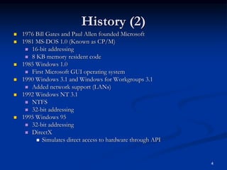
1) It discusses the history of Windows operating systems and how Vista came to be, building on predecessors like Windows NT, 2000, and XP.
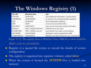
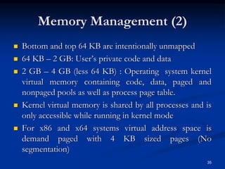
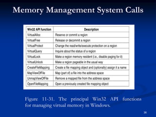
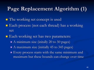
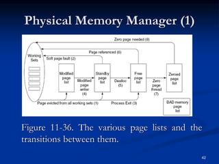
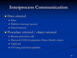
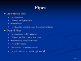
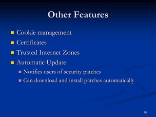
2) It describes the core components and architecture of Vista, including the kernel, processes, threads, memory management, and security features.
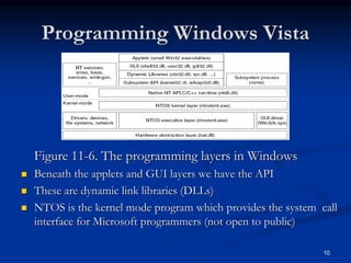
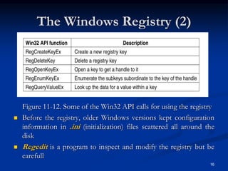
3) It explains the programming interfaces for Vista like Win32 and how they relate to the native NT API, allowing applications to be developed across versions of Windows.