The document presents information about the Carnot cycle, including:
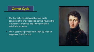
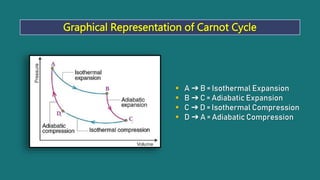
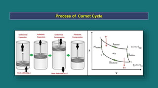
1) The Carnot cycle consists of four processes - two reversible isothermal processes and two reversible adiabatic processes.
2) It was proposed in 1824 by French engineer Sadi Carnot to study the maximum efficiency of heat engines.
3) Devices like vehicles, refrigerators, and air conditioners use the principles of the Carnot cycle to operate.