The document is a user guide for the GPSM Pro fuel level sensor, detailing its applications, specifications, installation, operation, and maintenance procedures. It provides essential information on connecting the sensor to power, installation guidelines, calibration processes, and operating rules. The guide emphasizes safety precautions and includes diagrams and technical specifications for effective usage and installation.
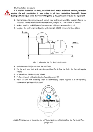


![[Blt] 기술경영을 위한 ip포트폴리오 전략 20160305 유철현 변리사](https://cdn.slidesharecdn.com/ss_thumbnails/bltip20160305-160303081252-thumbnail.jpg?width=640&height=640&fit=bounds)


