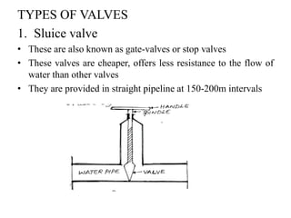
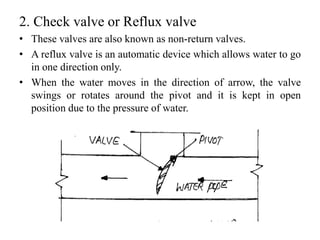
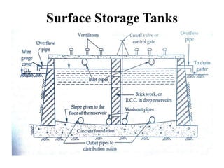
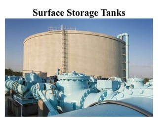
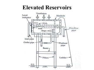
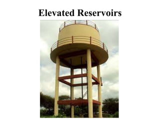
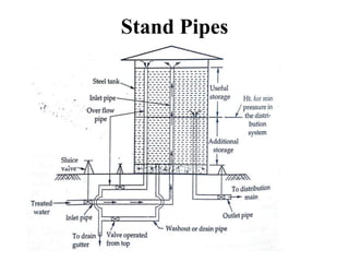
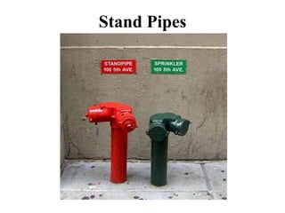
This document discusses various pipe appurtenances used in water distribution systems. It describes common appurtenances like fire hydrants, valves (sluice valves, check valves, air valves, drain valves, scour valves), and layouts of distribution networks (dead-end system, grid-iron system, ring system, radial system). It also covers distribution reservoirs (surface storage tanks, elevated storage tanks, stand pipes), their functions, and factors to consider when selecting pump horsepower for water distribution systems.
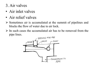


![Pipe materials and types of joints [autosaved]](https://cdn.slidesharecdn.com/ss_thumbnails/pipematerialsandtypesofjointsautosaved-180719140405-thumbnail.jpg?width=640&height=640&fit=bounds)