Downloaded 689 times
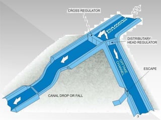


The document discusses various structures and devices used in irrigation canals, including cross regulators, head regulators, canal escapes, and flow meters. It explains their functions such as controlling water flow, managing silt entry, and ensuring proper discharge measurement. Additionally, it categorizes outlets based on their design and operational characteristics.