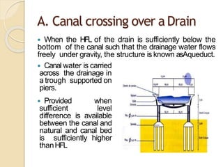
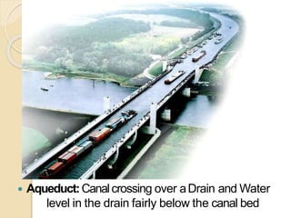
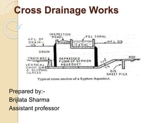
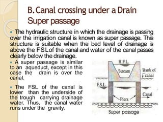
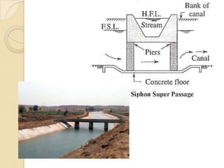
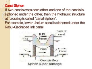
Cross drainage works carry the flow of a natural stream crossing a canal. The main types are aqueducts, siphon aqueducts, super passages, and siphons. Aqueducts are used when the canal bed is above the drain flood level, allowing gravity flow. Siphon aqueducts are used when the drain flood level is above the canal bed, requiring siphonic action. Super passages are used when the drain bed is above the canal supply level, with the canal flowing under the drain. Siphons are used when the canal supply level is above the drain bed. The selection depends on the relative water levels and sizes of the canal and drain.
Introduction, Term related to reservoir planning (Yield, Reservoir planning and operation curves, Reservoir storage, Reservoir clearance), Investigation for reservoir planning, Significance of mass curve and demand curves, Applications of mass-curve and demand curves, Fixation of reservoir capacity from annual inflow and outflow, Fixation of reservoir capacity.
Reservoir Planning: Introduction; Investigations for reservoir planning; Selection of site for a reservoir; Zones of storage in a reservoir; Storage capacity and yield; Mass inflow curve and demand curve; Calculation of reservoir capacity for a specified yield from the mass inflow curve; Determination of safe yield from a reservoir of a given capacity; Sediment flow in streams; Life of reservoir; Reservoir sediment control; flood routing. Various types of Spillways and design.
Present slideshow provides brief introductory part of various Intake Structures. This is useful for Environmental Engineering Students, faculties and learners.
Topics:
1. Types of Gravity Dam
2. Forces Acting on a Gravity Dam
3. Causes of failure of Gravity Dam
4. Elementary Profile of Gravity Dam
5. Practical Profile of Gravity Dam
6. Limiting height of Gravity Dam
7. Drainage and Inspection Galleries
Canal irrigation- (topics covered)
Types of Impounding structures: Gravity dam – Diversion Head works - Canal drop –
Cross drainage works – Canarl egulations – Canal outlets – Cana ll ining - Kennady s
and Lacey s Regim et heory
Canal fall- necessity and location- types of falls- Cross regulator and
distributory head regulator- their functions, Silt control devices, Canal
escapes- types of escapes.
This presentation is covered topic of cross drainage work. In which topics necessity of Cross drainage structures, their types and selection,
comparative merits and demerits, design of
various types of cross-drainage structure:aqueducts, siphon aqueduct, super passage
siphon, level crossing and other types covered.
A spillways is a structure constructed a or near the dam site to dispose of surplus water from the reservoir to the channel downstream.
https://engineeringuniverse1.blogspot.com/
spillway,types of spillways,
Design principles of Ogee spillways ,Spillway gates. Energy
Dissipaters and Stilling Basins Significance of Jump Height Curve and Tail Water Rating
Curve,
USBR and Indian types of Stilling Basins.
Welcome to WIPAC Monthly the magazine brought to you by the LinkedIn Group Water Industry Process Automation & Control.
In this month's edition, along with this month's industry news to celebrate the 13 years since the group was created we have articles including
A case study of the used of Advanced Process Control at the Wastewater Treatment works at Lleida in Spain
A look back on an article on smart wastewater networks in order to see how the industry has measured up in the interim around the adoption of Digital Transformation in the Water Industry.
Forklift Classes Overview by Intella PartsIntella Parts
Discover the different forklift classes and their specific applications. Learn how to choose the right forklift for your needs to ensure safety, efficiency, and compliance in your operations.
For more technical information, visit our website https://intellaparts.com
Using recycled concrete aggregates (RCA) for pavements is crucial to achieving sustainability. Implementing RCA for new pavement can minimize carbon footprint, conserve natural resources, reduce harmful emissions, and lower life cycle costs. Compared to natural aggregate (NA), RCA pavement has fewer comprehensive studies and sustainability assessments.
NUMERICAL SIMULATIONS OF HEAT AND MASS TRANSFER IN CONDENSING HEAT EXCHANGERS...ssuser7dcef0
Power plants release a large amount of water vapor into the
atmosphere through the stack. The flue gas can be a potential
source for obtaining much needed cooling water for a power
plant. If a power plant could recover and reuse a portion of this
moisture, it could reduce its total cooling water intake
requirement. One of the most practical way to recover water
from flue gas is to use a condensing heat exchanger. The power
plant could also recover latent heat due to condensation as well
as sensible heat due to lowering the flue gas exit temperature.
Additionally, harmful acids released from the stack can be
reduced in a condensing heat exchanger by acid condensation. reduced in a condensing heat exchanger by acid condensation.
Condensation of vapors in flue gas is a complicated
phenomenon since heat and mass transfer of water vapor and
various acids simultaneously occur in the presence of noncondensable
gases such as nitrogen and oxygen. Design of a
condenser depends on the knowledge and understanding of the
heat and mass transfer processes. A computer program for
numerical simulations of water (H2O) and sulfuric acid (H2SO4)
condensation in a flue gas condensing heat exchanger was
developed using MATLAB. Governing equations based on
mass and energy balances for the system were derived to
predict variables such as flue gas exit temperature, cooling
water outlet temperature, mole fraction and condensation rates
of water and sulfuric acid vapors. The equations were solved
using an iterative solution technique with calculations of heat
and mass transfer coefficients and physical properties.
Student information management system project report ii.pdfKamal Acharya
Our project explains about the student management. This project mainly explains the various actions related to student details. This project shows some ease in adding, editing and deleting the student details. It also provides a less time consuming process for viewing, adding, editing and deleting the marks of the students.
Overview of the fundamental roles in Hydropower generation and the components involved in wider Electrical Engineering.
This paper presents the design and construction of hydroelectric dams from the hydrologist’s survey of the valley before construction, all aspects and involved disciplines, fluid dynamics, structural engineering, generation and mains frequency regulation to the very transmission of power through the network in the United Kingdom.
Author: Robbie Edward Sayers
Collaborators and co editors: Charlie Sims and Connor Healey.
(C) 2024 Robbie E. Sayers
2. Define cross drainage work?
Definition: A cross drainage work is a
structure carrying the discharge from
a natural stream across a canal
intercepting the stream.
It is generally a very costly item and
should be avoided by:-
•Diverting one stream into another.
•Changing the alignment of the canal so
that it crosses below the junction of
two streams.
3. Selection of Site for a Cross
Drainage Structure
1 The canal and the drain should cross each other
at a right angle. Acute or obtuse angle crossing
should be avoided.
2 There should be sufficient straight reaches of
canal and
drain on both the upstream and the downstream
sides.
3 A sufficient reach of drain on the upstream should
be
stable and uniform.
4. TYPES OF CROSS DRAINAGE
WORKS
Depending upon levels and discharge, cross drainage
works may be grouped into following types:-
A. Canal crossing over a Drain
An Aqueduct
Siphon Aqueduct
B. Canal crossing under a Drain
Super passage
Siphon
C. Canal crossing a Drain at the same level
Level crossing
Drainage Inlet and Outlet
5. Selection of the Type of Cross
Drainage Structure
A. When the bed level of canal is sufficiently above
the highest flood level of the drain, an aqueduct is
constructed.
B. When the highest flood level of the drain is
higher than the bed level of the canal, the aqueduct
should be designed as siphon aqueduct.
C. When the bed level of the drain is sufficiently
higher than the full supply level of canal, cross
drainage work will be a super passage.
D. When the full supply level of the canal is above
the bed level of the drain, cross drainage work will
be a siphon.
E. If the bed levels of canal and drain are at the
same level, cross drainage structure is known as a
level crossing.
6. A. Canal crossing over a Drain
When the HFL of the drain is sufficiently below the
bottom of the canal such that the drainage water flows
freely under gravity, the structure is known asAqueduct.
Canal water is carried
across the drainage in
a trough supported on
piers.
Provided when
sufficient level
difference is available
between the canal and
natural and canal bed
is sufficiently higher
thanHFL
8. SiphonAqueduct:
In case of the siphon Aqueduct, the HFL of the drain is
much higher above the canal bed, and water runs under
siphonic action through the Aqueductbarrels.
The drain bed is generally depressed and provided with
pucca floors, on the upstream side either by a vertical drop
or by glacis of 3:1.
Thedownstream rising slope should not be steeper than
5:1.
When the canal is passed over the drain, the canal
remains open for inspection throughout and the damage
caused by flood is rare. However during heavy floods, the
foundations are susceptible to scour or the waterway of
drain may get choked due to debris, tressetc
9.
10. B.Canal crossing under a Drain
Super passage
The hydraulic structure in which the drainage is passing
over the irrigation canal is known as super passage. This
structure is suitable when the bed level of drainage is
above the FSLof the canal and water of the canal passes
clearly below the drainage.
A super passage is similar
to an aqueduct, except in this
case the drain is over the
canal.
The FSL of the canal is
lower than the underside of
the trough carrying drainage
water. Thus, the canal water
runs under the gravity.
11.
12. CanalSiphon
If two canals crosseach other and one of the canalsis
siphoned under the other, then the hydraulic structure
at crossing is called “canal siphon”.
For example, lower Jhelum canal is siphoned under the
Rasul-Qadirabad link canal.
13.
14. In case of siphon the FSL of the canal is much
above the bed level of the drainage trough, so that
the canal runs under the siphonicaction.
The canal bed is lowered and a ramp is provided
at the exit so that the trouble of silting is
minimized.
It is reverse of an siphon aqueduct.
In the above two types, the inspection road
cannot be provided along the canal and a separate
bridge is required for roadway. For economy, the
canal may be flumed but the drainage trough is
neverflumed.
15. Thefactors which affect the selection of
suitable type of cross drainage works are:
Relativebed levels and water drainage.
Size of the canal anddrainage.