Download to read offline


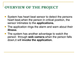
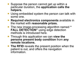
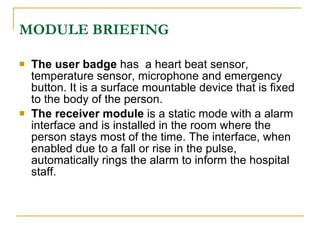
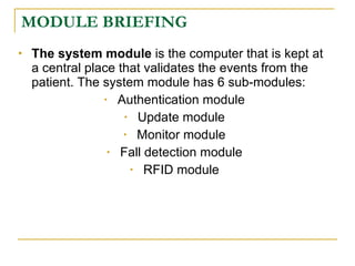


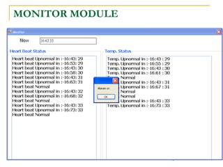


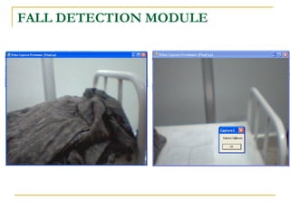
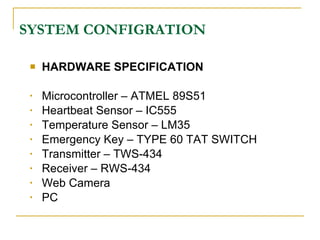

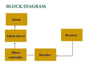
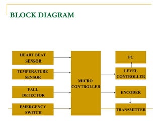
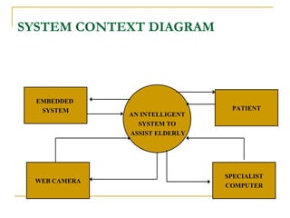


The document proposes an intelligent system to assist patients using wireless applications and low-cost equipment. The system has three main modules: a user badge module worn by the patient with sensors to detect vital signs, a receiver module at the patient's location, and a system module on a central computer. The system monitors the patient's heartbeat and temperature from the user badge and can detect falls using a web camera. If vital signs go outside normal ranges or a fall is detected, an alert is triggered to help patients in critical conditions.