Downloaded 109 times

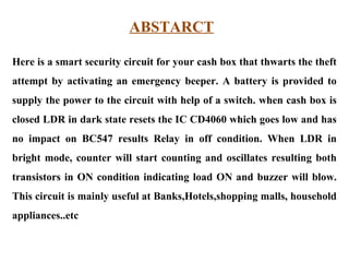
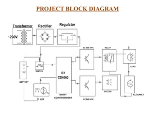
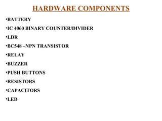


The document presents a project for an electronic eye-controlled security system designed to protect cash boxes. It discusses the components and functionalities of the circuit, including the use of an LDR (Light Dependent Resistor) to detect light when the box is opened, which triggers a buzzer and activates a relay. The system is particularly useful for security applications in locations such as banks and shopping malls.


