Downloaded 12 times

![RNATIONAL JOURNAL FOR TRENDS IN ENGINEERING & TECHNOLOGY
VOLUME 5 ISSUE 1 – MAY 2015 - ISSN: 2349 - 9303
81
REFERENCE
[1] Mohd Yamani Idna Idris, Mashkuri Yaacob,
Zaidi Razak, “A VHDL Implementation Of UART
Design with BIST capability”
[2] Dr. T.V.S.P. Gupta, Y. Kumari,M.Asok
Kumar”UART realization with BIST architecture
using VHDL” International Journal of Engineering
Research and Applications (IJERA) ISSN: 2248-
9622 www.ijera.com Vol. 3, Issue 1, January -
February 2013, pp.636-640.
[3] M.S. Harvey,Generic UART Manual,Silicon
Valley,December 1999
[4] P. J. Anderson, “The designer’s guide to
VHDL” , Morgan Kaufman , 2nd edition, 2002.
[5] Neil H.E. Weste, Kim Haase, David Harris, A.
Banerjee , “CMOS VLSI Design: A circuits and
Systems Perspective”, Pearson Education.
[6] K. Zarrineh, and S. J. Upadhyaya, “On
programmable memory built-in self test
architectures”, Design, Automation and Test in
Europe Conference and Exhibition 1999.
Proceedings, 1999, pp. 708 -713.
[7] Sandra Irobi Zaid Al-Ars Said
Hamdioui.Memory Test Optimizationfor Parasitic
Bit.
[8] N. Z. Haron, S.A.M. Junos, A.S.A. Aziz,
“Modelling and Simulation of Microcode Built-In
Self test Architecture for Embedded Memories”, In
Proc. of IEEE International Symposium on
Communications and Information Technologies pp.
136-139, 2007.
[9] S. Hamdioui, Z. Al-Ars, A.J. van de Goor,
“Testing Static andDynamic Faults in
Random Access Memories”, In Proc. of IEEE
VLSI Test Symposium, pp. 395-400, 2002.
[10]S. Hamdioui, et. al, “Importance of Dynamic
Faults for New SRAM Technologies”, In
IEEE Proc. Of European Test Workshop, pp.
29-34, 2003.
[11] International SEMATECH, “International
Technology Roadmap for Semiconductors
(ITRS): Edition 2001”.
12]A.J. van de Goor, “Testing Semiconductor
Memories, TheoryPractice” ComTex Publishing,
Gouda, Netherlands, 1998.
[13]A.J. van de Goor and Z. Al-Ars, “Functional
Fault Models: A Formal Notation and
Taxonomy”, In Proc. of IEEE VLSI Test
Symposium, pp. 281-289, 2000.
[14]“Xilinx ISE 6 Software Manuals and help –
PDF Collection”,
http://toolbox.xilinx.com/docsan/xilinx7/
books/manuals.pdf
[15]Zarrineh, K. and Upadhyaya, S.J., “On
Programmable memory built-in self test
architectures,” Design, Automation and Test
in Europ Conference and Exhibition 1999.
Proceedings , 1999, pp. 708 -713
[16]Sungju Park et al, “Microcode-Based Memory
BIST Implementing Modified March
Algorithms”, Journal of the Korean Physical
Society, Vol. 40, No. 4, April 2002, pp. 749-
753 SCEECS 2012
[17] A.J. van de Goor, “Using March tests to test
SRAMs”, Design & Test of Computers, IEEE,
Volume: 10, Issue: 1, March 1993 Pages: 8-
14.
[18] R. Dekker, F. Beenker and L. Thijssen, “Fault
Modeling and Test Algorithm Development
for Static Random Access Memories”
[19]R. Dekker, F. Beenker, L. Thijssen. “A realistic
fault model and test algorithm for static
random access memories”.IEEE Transactions
on CAD, Vol. 9(6), pp 567-572, June 1990.](https://image.slidesharecdn.com/ictte071-150928053950-lva1-app6892/85/Enhanced-Built-In-Self-Test-for-MSP-430-5-320.jpg)
![RNATIONAL JOURNAL FOR TRENDS IN ENGINEERING & TECHNOLOGY
VOLUME 5 ISSUE 1 – MAY 2015 - ISSN: 2349 - 9303
82
[20]B. F. Cockburn: “Tutorial on Semiconductor
Memory Testing” Journal of Electronic
Testing: Theory and Applications, 5, pp 321-
336 1994 Kluwer Academic Publishers.](https://image.slidesharecdn.com/ictte071-150928053950-lva1-app6892/85/Enhanced-Built-In-Self-Test-for-MSP-430-6-320.jpg)

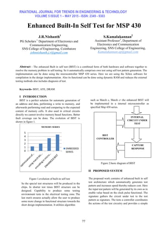
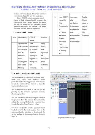
The document discusses an enhanced built-in self-test (BIST) architecture for the MSP430 microcontroller aimed at memory testing. This approach combines hardware and software for automatic test pattern generation, improving test speed and reducing costs while ensuring better fault coverage. The methodology utilizes algorithms like March C and dynamic RAM for more efficient testing procedures without relying on external equipment.