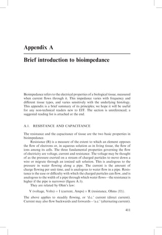
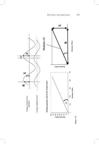
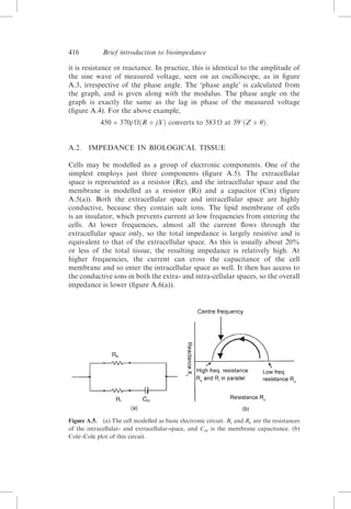
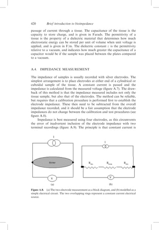
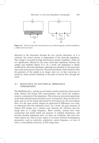
SlideShare a Scribd company logo
Appendix A
Brief introduction to bioimpedance

Bioimpedance refers to the electrical properties of a biological tissue, measured
when current flows through it. This impedance varies with frequency and
different tissue types, and varies sensitively with the underlying histology.
This appendix is a brief summary of its principles; we hope it will be useful
for any non-technical readers new to EIT. The section is unreferenced; a
suggested reading list is attached at the end.

A.1.

RESISTANCE AND CAPACITANCE

The resistance and the capacitance of tissue are the two basic properties in
bioimpedance.
Resistance (R) is a measure of the extent to which an element opposes
the flow of electrons or, in aqueous solution as in living tissue, the flow of
ions among its cells. The three fundamental properties governing the flow
of electricity are voltage, current and resistance. The voltage may be thought
of as the pressure exerted on a stream of charged particles to move down a
wire or migrate through an ionized salt solution. This is analogous to the
pressure in water flowing along a pipe. The current is the amount of
charge flowing per unit time, and is analogous to water flow in a pipe. Resistance is the ease or difficulty with which the charged particles can flow, and is
analogous to the width of a pipe through which water flows—the resistance is
higher if the pipe is narrower (figure A.1).
They are related by Ohm’s law:
V (voltage, Volts) ¼ I (current, Amps) Â R (resistance, Ohms ðÞÞ:
The above applies to steadily flowing, or ‘d.c.’ current (direct current).
Current may also flow backwards and forwards—‘a.c.’ (alternating current).
411
412

Brief introduction to bioimpedance

Figure A.1.

Basic concepts—current, voltage and resistance. Analogy to water flow.

Resistance has the same effect on a.c. current as d.c. current. Capacitance (C)
is an expression of the extent to which an electronic component, circuit or
system, stores and releases energy as the current and voltage fluctuate with
each a.c. cycle. The capacitance physically corresponds to the ability of
plates in a capacitor to store charge. With each cycle, charges accumulate
and then discharge. Direct current cannot pass through a capacitor. A.c.
can pass because of the rapidly reversing flux of charge. The capacitance is
an unvarying property of a capacitive or more complex circuit. However,
the effect in terms of the ease of current passage depends on the frequency
of the applied current—charges pass backwards and forwards more rapidly
if the applied frequency is higher.
For the purposes of bioimpedance, a useful concept for current travelling through a capacitance is ‘reactance’ (X). The reactance is analogous to
resistance—a higher reactance has a higher effective resistance to alternating
current. Like resistance, its value is in Ohms, but it depends on the applied
frequency, which should be specified (figure A.2).
The relationship is
Reactance (Ohms) ¼ 1=ð2 Â Å Â Frequency ðHzÞ Â Capacitance ðFaradsÞÞ:
When a current is passing through a purely resistive circuit, the voltage
recorded across the resistor will coincide exactly with the timing, or phase,
of the applied alternating current, as one would expect. In the water flow
analogy, an increase in pressure across a narrowing will be instantly followed
by an increase in flow. When current flows across a capacitor, the voltage
recorded across it lags behind the applied current. This is because the back
and forth flow of current depends on repeated charging and discharging of
the plates of the capacitor. This takes a little time to develop. To pursue the
water analogy, a capacitor would be equivalent to a taut membrane stretched
Resistance and capacitance

Figure A.2.

413

Capacitance, reactance and effect of frequency.

across the pipe. No continuous flow could pass. However, if the flow is
constantly reversed, then for each new direction, a little water will flow as
the membrane bulges, and then flow back the other way when the flow
reverses. The development of pressure on the membrane will only build up
after some water has flowed into the membrane to stretch it. In terms of a
sine wave which has 3608 in a full cycle, the lag is one quarter of a cycle, or 908.
In practice, this is seen if an oscilloscope is set up as in figure A.3. An
ideal (confused with d.c.) current a.c. source passes current across a resistor
or capacitor. The current delivered by the source is displayed on the upper
trace. The voltage measured over the components is displayed on the lower
trace. When this is across a resistor, it is in phase—when across a capacitor,
it lags by 908 and is said to be ‘out-of-phase’. When the circuit contains a
mixture of resistance and capacitance, the phase is intermediate between 0
and 908, and depends on the relative contributions from resistance and
capacitance. As a constant current is applied, the total combination of
resistance or reactance, the impedance can be calculated by Ohm’s law
from the amplitude of the voltage at the peak of the sine wave.
414

Brief introduction to bioimpedance

Figure A.3. The voltage that results from an applied current is in phase for a resistor (A)
and 908 out of phase for a capacitor.

Impedance is made of these two components, resistance or the real part
of the data, and reactance, the out-of-phase data. These are usually displayed
on a graph in which resistance is the x axis and reactance is the y axis. This is
termed the ‘complex’ impedance, and the graph is the ‘complex’ plane. For
mathematical reasons to do with solutions of the equations for the sine
waves of the a.c. voltages, the in-phase resistive component is considered
to be a ‘real’ or normal number. The out-of-phase, capacitative, component
is considered to be ‘imaginary’. This means that the amplitude of the
capacitative voltage, a real number such as 3.2 V, is multiplied by ‘j’, which
is the square root of minus 1. Thus, a typical complex impedance might be
written as
450 þ 370j:
This would mean that the resistance is 450  and the reactance is 370 , and
would be displayed on the complex plane as in figure A.4, with the resistance
on the x axis and reactance on the y axis. Another equivalent way is to
calculate the length of the impedance line, which passes from the origin of
the graph to the complex impedance point. This is termed the ‘modulus’ of
the impedance (Z), and means its total amplitude, irrespective of whether
415

Figure A.4.

Resistance and capacitance
416

Brief introduction to bioimpedance

it is resistance or reactance. In practice, this is identical to the amplitude of
the sine wave of measured voltage, seen on an oscilloscope, as in figure
A.3, irrespective of the phase angle. The ‘phase angle’ is calculated from
the graph, and is given along with the modulus. The phase angle on the
graph is exactly the same as the lag in phase of the measured voltage
(figure A.4). For the above example,
450 þ 370j ðR þ jXÞ converts to 583  at 398ðZ þ Þ:

A.2. IMPEDANCE IN BIOLOGICAL TISSUE
Cells may be modelled as a group of electronic components. One of the
simplest employs just three components (figure A.5). The extracellular
space is represented as a resistor (Re), and the intracellular space and the
membrane is modelled as a resistor (Ri) and a capacitor (Cm) (figure
A.5(a)). Both the extracellular space and intracellular space are highly
conductive, because they contain salt ions. The lipid membrane of cells
is an insulator, which prevents current at low frequencies from entering the
cells. At lower frequencies, almost all the current flows through the
extracellular space only, so the total impedance is largely resistive and is
equivalent to that of the extracellular space. As this is usually about 20%
or less of the total tissue, the resulting impedance is relatively high. At
higher frequencies, the current can cross the capacitance of the cell
membrane and so enter the intracellular space as well. It then has access to
the conductive ions in both the extra- and intra-cellular spaces, so the overall
impedance is lower (figure A.6(a)).

Figure A.5. (a) The cell modelled as basic electronic circuit. Ri and Re are the resistances
of the intracellular- and extracellular-space, and Cm is the membrane capacitance. (b)
Cole–Cole plot of this circuit.
Impedance in biological tissue

417

Figure A.6. (a) The movement of current through cells at both low and high frequencies.
(b) Idealized Cole–Cole plot for tissue.

The movement of the current in the different compartments of the cellular
spaces at different frequencies, and the related resistance and reactance values
measured, is usefully displayed as a Cole–Cole plot. This is an extension of the
resistance/reactance plot in the complex plane. Instead of the single point for a
measurement at one frequency, as in figure A.4, the values for a range of
frequencies are all superimposed. For simple electronic components, the arc
will be a semicircle (figure A.5(b)). At low frequencies, the measurement is
only resistive, and corresponds to the extracellular resistance—no current
passes through the intracellular path because it cannot cross the cell membrane
capacitance. As the applied frequency increases, the phase angle gradually
increases as more current is diverted away from the extracellular resistance,
and passes through the capacitance of the intracellular route. At high frequencies, the intracellular capacitance becomes negligible, so current enters the
parallel resistances of the intracellular and extracellular compartments. The
cell membrane reactance is now nil, so the entire impedance again is just
resistive and so returns to the X axis. Between these, the current passing
through the capacitative path reaches a peak. The frequency at which this
418

Brief introduction to bioimpedance

occurs is known as the centre frequency (Fc), and is a useful measure of the
properties of an impedance. In real tissue, the Cole–Cole plot is not exactly
semicircular, because the detailed situation is clearly much more complex;
the plot is usually approximately semicircular, but the centre of the circle
lies below the x-axis. Inspection of the Cole–Cole plot yields the high- and
low-frequency resistances, as the intercept with the x-axis, and the centre
frequency is the point at which the phase angle is greatest. The angle of depression of the centre of the semicircle is another means of characterizing the tissue
(figure A.6(b)).
Over the frequency ranges used for EIT and MIT, about 100 Hz to
100 MHz, the resistance and reactance of tissue gradually decreases. This is
due to the simple effect of increased frequency passing more easily across capacitance, but also because cellular and biochemical mechanisms begin to operate, which increases the ease of passage of the electrical current. A
remarkable feature of live tissue is an extraordinarily high capacitance, which
is up to 1000 times greater than inorganic materials, such as plastics used in
capacitors. This is because capacitance is provided by the numerous and closely
opposed cell membranes of cells, each of which behaves as a tiny capacitor.
Over this frequency range, there are certain frequency bands where the phase
angle increases, because mechanisms come into play which provide more capacitance. They may be seen as regions of an increased decrease of resistance in a
plot of resistance against frequency, and are termed ‘dispersions’. At the low
end of the frequency spectrum, the outer cell membrane of most cells is able
to charge and discharge fully. This region is known as the alpha dispersion
and is usually centred at about 100 Hz.
As the frequency increases, from 10 kHz–10 MHz, the membrane only
partially charges and the current charges the small intracellular space structures, which behave largely as capacitances. At these higher frequencies the
current can flow through the lipid cell membranes, introducing a capacitive
component. This makes the higher frequencies sensitive to intracellular
changes due to structural relaxation. This effect is largest around 100 kHz,
and is termed the ‘beta dispersion’. At the highest frequencies, dipolar
reorientation of proteins and organelles can occur, and affect the impedance
measurements of extra- and intracellular environments. This is the gamma
dispersion, and is due to the relaxation of water molecules and is centred
at 10 GHz. Most changes between normal and pathological tissues occur
in the alpha and beta dispersion spectrum.
A.3. OTHER RELATED MEASURES OF IMPEDANCE
A.3.1.

Unit values of impedance

Resistance and reactance, as described above, are fixed measures of individual components or samples. It is useful to be able to describe the general
Other related measures of impedance

Figure A.7.
measured.

419

The effect of changing the length or cross-sectional area of the tissue sample

properties of a material. The impedance of a sample increases, as one would
expect, with increasing length of the sample between the measuring electrodes. Somewhat counter-intuitively, it decreases if the area contacting the
measuring electrodes increases—this is because there is more conductive
material to carry the current. The individual values for resistance or
reactance can be converted to the general property—termed ‘resistivity’ or
‘reactivity’ by adjusting for these. Resistivity  is given in :m and is the
ability of a material to resist the passage of electrical current for a defined
unit of tissue (figure A.7). It is calculated as
ð:mÞ ¼ ResistanceðÞ Â Area=Length:
The capacitative element of a material can be considered in the same way—
the ‘reactivity’ is also measured in :m and is the general resistance property
of a material, at a specified frequency.
A.3.2.

Other indices of impedance

The resistance and reactance fully describe the impedance of tissue, but there
are several other related measures which are, sometimes confusingly, used in
the EIT and Bioimpedance, literature. These arise because different, reciprocal, terms may be used to describe the ease, as opposed to the difficulty, of
passage of current. Secondly, with respect to capacitance, one can choose
to use the effective resistance at a given frequency—the reactance, or the
intrinsic property of the material, the capacitance, which is independent of
frequency. Each of the different measures may be suffixed with ‘-ivity’ to
yield its general property. Finally, the measure given may refer to the
complex impedance rather than the in- or out-of-phase component.
Not all permutations, fortunately, are widely used. These are the most
common: the conductivity  is the inverse of resistivity and is given in
Siemens/m or, more usually, S/m. The admittance is the inverse of
impedance, and so is a combined measure of in- and out-of-phase ease of
420

Brief introduction to bioimpedance

passage of current through a tissue. The capacitance of the tissue is the
capacity to store charge, and is given in Farads. The permittivity of a
tissue is the property of a dielectric material that determines how much
electrostatic energy can be stored per unit of volume when unit voltage is
applied, and is given in F/m. The dielectric constant  is the permittivity
relative to a vacuum, and indicates how much greater the capacitance of a
capacitor would be if the sample was placed between the plates compared
to a vacuum.

A.4. IMPEDANCE MEASUREMENT
The impedance of samples is usually recorded with silver electrodes. The
simplest arrangement is to place electrodes at either end of a cylindrical or
cuboidal sample of the tissue. A constant current is passed and the
impedance is calculated from the measured voltage (figure A.7). The drawback of this method is that the impedance measured includes not only the
tissue sample, but also that of the electrodes. The method can be reliable,
but requires that a calibration procedure is performed first to establish the
electrode impedance. These then need to be subtracted from the overall
impedance recorded, and it should be a fair assumption that the electrode
impedances do not change between the calibration and test procedures (see
figure A.8).
Impedance is best measured using four electrodes, as this circumvents
the error of inadvertent inclusion of the electrode impedance with two
terminal recordings (figure A.9). The principle is that constant current is

Figure A.8. (a) The two-electrode measurement as a block diagram, and (b) modelled as a
simple electrical circuit. The two overlapping rings represent a constant current electrical
source.
Relevance to electrical impedance tomography

421

Figure A.9. The four-electrode measurement as (a) a block diagram, and (b) modelled as
a simple electrical circuit.

delivered to the electrodes through the two current electrodes; as it is
constant, the correct current is independent of the electrode impedance.
The voltage is recorded by high performance modern amplifiers, which are
not significantly affected by the series electrodes impedance between the
sample and amplifier (figure A.7). As a result, the impedance is ideally
unaffected by electrode impedance, although non-idealities in the electronics
may cause inaccuracies in practice. The main drawback of this method is that
the geometry of the sample is no longer clear cut, so that conversion to
resistivity needs careful modelling of the path of current flow through the
tissue.

A.5.

RELEVANCE TO ELECTRICAL IMPEDANCE
TOMOGRAPHY

The Sheffield mark 1, and the several similar systems which have been used to
make clinical and human EIT measurements, only record the in-phase,
resistive, component of the impedance. This is because unwanted capacitance
in the leads and electronics introduce errors. Fortunately, these are all out-ofphase and so can be largely discounted by throwing away the out-of-phase
data. For the same reason, images are generated of differences over time,
as subtraction like this minimizes errors. As a result, the great majority of
clinical EIT images are a unitless ratio between the reference and test
image data at a single frequency. More recently, systems have been
constructed and tested which can measure at multiple frequencies, and
provide absolute impedance data. As these are validated, and come into
wider clinical use, then we may expect to see more absolute bioimpedance
parameters, such as resistivity, admittivity, centre frequency, or ratio of
extra- to intracellular resistivity, in EIT image data.
422

Brief introduction to bioimpedance

FURTHER READING
Duck F A 1990 Physical properties of tissue: a comprehensive reference book. London:
Academic Press
Gabriel C, Gabriel S and Corthout E 1996a The dielectric properties of biological tissues: I.
Literature survey Physics in Medicine and Biology 41 2231–2249
Gabriel S, Lau R and Gabriel C 1996b The dielectric properties of biological tissues: II.
Measurements in the frequency range 10 Hz to 20 GHz Physics in Medicine and Biology 41 2251–2269
Geddes L B L E 1967 The specific resistance of biological material—a compendium of data
for the biomedical engineer and physiologist Med. Biol. Eng. 5 271–293
Grimnes S and Martinsen Ø G 2000 Bioimpedance and bioelectricity basics. London:
Academic Press

More Related Content

What's hot

La bifurcation coronaire
La bifurcation coronaireLa bifurcation coronaire
La bifurcation coronaire
Hervé Faltot
 
Diuretics, dialysis
Diuretics, dialysisDiuretics, dialysis
Diuretics, dialysis
DrChintansinh Parmar
 
Energetics of Skeletal Muscle Contraction
Energetics of Skeletal Muscle ContractionEnergetics of Skeletal Muscle Contraction
Energetics of Skeletal Muscle Contraction
UMAMAHISHAQ
 
carotid angioplasty
carotid angioplastycarotid angioplasty
carotid angioplasty
Gopi Krishna Rayidi
 
MR DIFFUSION PERFUSION & ARTIFACTS.pptx
MR DIFFUSION PERFUSION & ARTIFACTS.pptxMR DIFFUSION PERFUSION & ARTIFACTS.pptx
MR DIFFUSION PERFUSION & ARTIFACTS.pptx
yasna kibria
 
Coronary stent
Coronary stentCoronary stent
Coronary stent
Other Mother
 
CT SCAN
CT SCANCT SCAN
Bone marrow density (BMD)
Bone marrow density (BMD)Bone marrow density (BMD)
Bone marrow density (BMD)
MD Rahman
 
BMD Learning
BMD LearningBMD Learning
BMD Learning
Behzad Ommani
 
Osmolarity vs. Osmolality
Osmolarity vs. OsmolalityOsmolarity vs. Osmolality
Osmolarity vs. Osmolality
Kavya Liyanage
 
Action potential
Action potentialAction potential
Action potential
Ilyas Raza
 
Principles of Doppler ultrasound
Principles of Doppler ultrasoundPrinciples of Doppler ultrasound
Principles of Doppler ultrasound
Samir Haffar
 
interventional cardiology, Guiding catheters, wires, and balloons equipment...
 interventional cardiology, Guiding catheters, wires, and balloons  equipment... interventional cardiology, Guiding catheters, wires, and balloons  equipment...
interventional cardiology, Guiding catheters, wires, and balloons equipment...
salman habeeb
 
Physiology PG Questions
Physiology PG QuestionsPhysiology PG Questions
Physiology PG Questions
Raghu Veer
 
Ultrasound Transducer Types
Ultrasound Transducer TypesUltrasound Transducer Types
Ultrasound Transducer Types
Mette Lyng
 
Cardiovascular Imaging
Cardiovascular ImagingCardiovascular Imaging
Cardiovascular Imaging
Muhammad Ayub
 
Glucose reabsorption
Glucose reabsorptionGlucose reabsorption
Glucose reabsorption
SanjogBam
 
Ultrasound in undifferentiated shock
Ultrasound in undifferentiated shockUltrasound in undifferentiated shock
Ultrasound in undifferentiated shock
SCGH ED CME
 
Membrane potentials
Membrane potentials Membrane potentials
Membrane potentials
Dr.Nusrat Tariq
 
Coronary guide wires
Coronary guide wires  Coronary guide wires
Coronary guide wires
Malleswara rao Dangeti
 

What's hot (20)

La bifurcation coronaire
La bifurcation coronaireLa bifurcation coronaire
La bifurcation coronaire
 
Diuretics, dialysis
Diuretics, dialysisDiuretics, dialysis
Diuretics, dialysis
 
Energetics of Skeletal Muscle Contraction
Energetics of Skeletal Muscle ContractionEnergetics of Skeletal Muscle Contraction
Energetics of Skeletal Muscle Contraction
 
carotid angioplasty
carotid angioplastycarotid angioplasty
carotid angioplasty
 
MR DIFFUSION PERFUSION & ARTIFACTS.pptx
MR DIFFUSION PERFUSION & ARTIFACTS.pptxMR DIFFUSION PERFUSION & ARTIFACTS.pptx
MR DIFFUSION PERFUSION & ARTIFACTS.pptx
 
Coronary stent
Coronary stentCoronary stent
Coronary stent
 
CT SCAN
CT SCANCT SCAN
CT SCAN
 
Bone marrow density (BMD)
Bone marrow density (BMD)Bone marrow density (BMD)
Bone marrow density (BMD)
 
BMD Learning
BMD LearningBMD Learning
BMD Learning
 
Osmolarity vs. Osmolality
Osmolarity vs. OsmolalityOsmolarity vs. Osmolality
Osmolarity vs. Osmolality
 
Action potential
Action potentialAction potential
Action potential
 
Principles of Doppler ultrasound
Principles of Doppler ultrasoundPrinciples of Doppler ultrasound
Principles of Doppler ultrasound
 
interventional cardiology, Guiding catheters, wires, and balloons equipment...
 interventional cardiology, Guiding catheters, wires, and balloons  equipment... interventional cardiology, Guiding catheters, wires, and balloons  equipment...
interventional cardiology, Guiding catheters, wires, and balloons equipment...
 
Physiology PG Questions
Physiology PG QuestionsPhysiology PG Questions
Physiology PG Questions
 
Ultrasound Transducer Types
Ultrasound Transducer TypesUltrasound Transducer Types
Ultrasound Transducer Types
 
Cardiovascular Imaging
Cardiovascular ImagingCardiovascular Imaging
Cardiovascular Imaging
 
Glucose reabsorption
Glucose reabsorptionGlucose reabsorption
Glucose reabsorption
 
Ultrasound in undifferentiated shock
Ultrasound in undifferentiated shockUltrasound in undifferentiated shock
Ultrasound in undifferentiated shock
 
Membrane potentials
Membrane potentials Membrane potentials
Membrane potentials
 
Coronary guide wires
Coronary guide wires  Coronary guide wires
Coronary guide wires
 

Viewers also liked

CV SiF en
CV SiF enCV SiF en
CV SiF en
Simon Fessard
 
How Social Software Helps 350,000 Men's Wearhouse Customers Dress Better Ever...
How Social Software Helps 350,000 Men's Wearhouse Customers Dress Better Ever...How Social Software Helps 350,000 Men's Wearhouse Customers Dress Better Ever...
How Social Software Helps 350,000 Men's Wearhouse Customers Dress Better Ever...
tibbr
 
Pm的知识架构
Pm的知识架构Pm的知识架构
Pm的知识架构
efrog
 
201302 gast mol-longa sil (1)
201302 gast mol-longa sil (1)201302 gast mol-longa sil (1)
201302 gast mol-longa sil (1)
Johnny Curo Manchego
 
Fidelizacion de clientes en el entorno digital
Fidelizacion de clientes en el entorno digital Fidelizacion de clientes en el entorno digital
Fidelizacion de clientes en el entorno digital
Victoria Blanco Alegria
 
Leg Avenue Marketing
Leg Avenue MarketingLeg Avenue Marketing
Leg Avenue Marketing
barbara gleason
 
8971826 Poesias De Francois Villon
8971826 Poesias De Francois Villon8971826 Poesias De Francois Villon
8971826 Poesias De Francois Villon
Izaskun Uzkudun
 
LR Beauty Collection (ENG) 2|2015
LR Beauty Collection (ENG) 2|2015LR Beauty Collection (ENG) 2|2015
LR Beauty Collection (ENG) 2|2015
Zissis Ahladas
 
Pensamientos y frases cèlebres iii
Pensamientos y frases cèlebres iiiPensamientos y frases cèlebres iii
Pensamientos y frases cèlebres iii
juanchojuancho
 
Heavy Duty Linear Actuators, Belt Driven Actuators: MXB
Heavy Duty Linear Actuators, Belt Driven Actuators: MXBHeavy Duty Linear Actuators, Belt Driven Actuators: MXB
Heavy Duty Linear Actuators, Belt Driven Actuators: MXB
Tolomatic
 
Tipos de Personalidades
Tipos de PersonalidadesTipos de Personalidades
Tipos de Personalidades
2678655
 
Les boissons pétillantes et colorées
Les boissons pétillantes et coloréesLes boissons pétillantes et colorées
Les boissons pétillantes et colorées
Lycée Français René-Verneau
 
Cómo conseguir mayor productividad y competitividad a través de la dirección ...
Cómo conseguir mayor productividad y competitividad a través de la dirección ...Cómo conseguir mayor productividad y competitividad a través de la dirección ...
Cómo conseguir mayor productividad y competitividad a través de la dirección ...
Elizabeth Ontaneda
 
Ericsson-LG Enterprise Introduction
Ericsson-LG Enterprise IntroductionEricsson-LG Enterprise Introduction
Ericsson-LG Enterprise Introduction
Ericsson-LG Enterprise
 
Prog convivencia civismo de 7mo a 9no Mined Nicaragua
Prog convivencia civismo de 7mo a 9no  Mined Nicaragua Prog convivencia civismo de 7mo a 9no  Mined Nicaragua
Prog convivencia civismo de 7mo a 9no Mined Nicaragua
Cliffor Jerry Herrera Castrillo
 
Learning Single page Application chapter 1
Learning Single page Application chapter 1Learning Single page Application chapter 1
Learning Single page Application chapter 1
Puguh Rismadi
 
Técnica quirurgica lavado de manos
Técnica quirurgica lavado de manosTécnica quirurgica lavado de manos
Técnica quirurgica lavado de manos
yumizita
 
Revlon Brand Experiences - BIC Class Project
Revlon Brand Experiences - BIC Class ProjectRevlon Brand Experiences - BIC Class Project
Revlon Brand Experiences - BIC Class Project
Alexandra Suazo
 
Tema 4. Core Energía
Tema 4. Core EnergíaTema 4. Core Energía
Tema 4. Core Energía
Laura O. Eguia Magaña
 
Direccion y control ppt (1)
Direccion y control ppt (1)Direccion y control ppt (1)
Direccion y control ppt (1)
Mary Stephani Perales Ruiz
 

Viewers also liked (20)

CV SiF en
CV SiF enCV SiF en
CV SiF en
 
How Social Software Helps 350,000 Men's Wearhouse Customers Dress Better Ever...
How Social Software Helps 350,000 Men's Wearhouse Customers Dress Better Ever...How Social Software Helps 350,000 Men's Wearhouse Customers Dress Better Ever...
How Social Software Helps 350,000 Men's Wearhouse Customers Dress Better Ever...
 
Pm的知识架构
Pm的知识架构Pm的知识架构
Pm的知识架构
 
201302 gast mol-longa sil (1)
201302 gast mol-longa sil (1)201302 gast mol-longa sil (1)
201302 gast mol-longa sil (1)
 
Fidelizacion de clientes en el entorno digital
Fidelizacion de clientes en el entorno digital Fidelizacion de clientes en el entorno digital
Fidelizacion de clientes en el entorno digital
 
Leg Avenue Marketing
Leg Avenue MarketingLeg Avenue Marketing
Leg Avenue Marketing
 
8971826 Poesias De Francois Villon
8971826 Poesias De Francois Villon8971826 Poesias De Francois Villon
8971826 Poesias De Francois Villon
 
LR Beauty Collection (ENG) 2|2015
LR Beauty Collection (ENG) 2|2015LR Beauty Collection (ENG) 2|2015
LR Beauty Collection (ENG) 2|2015
 
Pensamientos y frases cèlebres iii
Pensamientos y frases cèlebres iiiPensamientos y frases cèlebres iii
Pensamientos y frases cèlebres iii
 
Heavy Duty Linear Actuators, Belt Driven Actuators: MXB
Heavy Duty Linear Actuators, Belt Driven Actuators: MXBHeavy Duty Linear Actuators, Belt Driven Actuators: MXB
Heavy Duty Linear Actuators, Belt Driven Actuators: MXB
 
Tipos de Personalidades
Tipos de PersonalidadesTipos de Personalidades
Tipos de Personalidades
 
Les boissons pétillantes et colorées
Les boissons pétillantes et coloréesLes boissons pétillantes et colorées
Les boissons pétillantes et colorées
 
Cómo conseguir mayor productividad y competitividad a través de la dirección ...
Cómo conseguir mayor productividad y competitividad a través de la dirección ...Cómo conseguir mayor productividad y competitividad a través de la dirección ...
Cómo conseguir mayor productividad y competitividad a través de la dirección ...
 
Ericsson-LG Enterprise Introduction
Ericsson-LG Enterprise IntroductionEricsson-LG Enterprise Introduction
Ericsson-LG Enterprise Introduction
 
Prog convivencia civismo de 7mo a 9no Mined Nicaragua
Prog convivencia civismo de 7mo a 9no  Mined Nicaragua Prog convivencia civismo de 7mo a 9no  Mined Nicaragua
Prog convivencia civismo de 7mo a 9no Mined Nicaragua
 
Learning Single page Application chapter 1
Learning Single page Application chapter 1Learning Single page Application chapter 1
Learning Single page Application chapter 1
 
Técnica quirurgica lavado de manos
Técnica quirurgica lavado de manosTécnica quirurgica lavado de manos
Técnica quirurgica lavado de manos
 
Revlon Brand Experiences - BIC Class Project
Revlon Brand Experiences - BIC Class ProjectRevlon Brand Experiences - BIC Class Project
Revlon Brand Experiences - BIC Class Project
 
Tema 4. Core Energía
Tema 4. Core EnergíaTema 4. Core Energía
Tema 4. Core Energía
 
Direccion y control ppt (1)
Direccion y control ppt (1)Direccion y control ppt (1)
Direccion y control ppt (1)
 

Similar to Bioimpedance overview

Power Circuits and Transforers-Unit 3 Labvolt Student Manual
Power Circuits and Transforers-Unit 3 Labvolt Student ManualPower Circuits and Transforers-Unit 3 Labvolt Student Manual
Power Circuits and Transforers-Unit 3 Labvolt Student Manual
phase3-120A
 
Electrical properies of the tissues
Electrical properies of the tissuesElectrical properies of the tissues
Electrical properies of the tissues
Juliana Knocikova
 
AC circuit
AC circuitAC circuit
AC circuit
Roppon Picha
 
NETWORK ANALYSIS PART 3 For GATE IES PSU -2020 RRB/SSC AE JE TECHNICAL INT...
NETWORK ANALYSIS PART 3 For  GATE IES PSU  -2020 RRB/SSC  AE JE TECHNICAL INT...NETWORK ANALYSIS PART 3 For  GATE IES PSU  -2020 RRB/SSC  AE JE TECHNICAL INT...
NETWORK ANALYSIS PART 3 For GATE IES PSU -2020 RRB/SSC AE JE TECHNICAL INT...
Prasant Kumar
 
Electronics & Electrical Essential Description
Electronics & Electrical Essential DescriptionElectronics & Electrical Essential Description
Electronics & Electrical Essential Description
Kavin Henry
 
Basic Terms of Circuit Breaker
Basic Terms of Circuit BreakerBasic Terms of Circuit Breaker
Basic Terms of Circuit Breaker
AnshulShekhar3
 
Digital electronics
Digital electronicsDigital electronics
Digital electronics
Prof. Dr. K. Adisesha
 
Ch 20 Electric Circuits
Ch 20 Electric CircuitsCh 20 Electric Circuits
Ch 20 Electric Circuits
Scott Thomas
 
Mesh and nodal
Mesh and nodalMesh and nodal
Mesh and nodal
Aneesh Pavan Prodduturu
 
13 pius augustine electric current
13 pius augustine electric current13 pius augustine electric current
13 pius augustine electric current
PiusAugustine
 
AC.pptx
AC.pptxAC.pptx
AC.pptx
xdarlord
 
Electricity
ElectricityElectricity
Electricity
riomar catinguel
 
Exp SPA - Chp 17 Current of Electricity
Exp SPA - Chp 17 Current of ElectricityExp SPA - Chp 17 Current of Electricity
Exp SPA - Chp 17 Current of Electricity
harrywwh
 
Basic laws
Basic lawsBasic laws
current ,current density , Equation of continuity
current ,current density , Equation of continuitycurrent ,current density , Equation of continuity
current ,current density , Equation of continuity
Muhammad Salman
 
7 - Rangkuman Rangkaian DC KELAS 12.pptx
7 - Rangkuman Rangkaian DC KELAS 12.pptx7 - Rangkuman Rangkaian DC KELAS 12.pptx
7 - Rangkuman Rangkaian DC KELAS 12.pptx
anishasalsabila
 
Corrosion Report
Corrosion ReportCorrosion Report
Corrosion Report
Ahmad Shumayal
 
Chameli Devi Group of Institution(BEE) (2).pptx
Chameli Devi Group of Institution(BEE) (2).pptxChameli Devi Group of Institution(BEE) (2).pptx
Chameli Devi Group of Institution(BEE) (2).pptx
10croreviews
 
lecture note AC fundamental LESSON 2.pptx
lecture note AC fundamental LESSON 2.pptxlecture note AC fundamental LESSON 2.pptx
lecture note AC fundamental LESSON 2.pptx
kifle203
 
Conductors, Capacitors, Dielectrics
Conductors, Capacitors, Dielectrics Conductors, Capacitors, Dielectrics
Conductors, Capacitors, Dielectrics
josealberto21
 

Similar to Bioimpedance overview (20)

Power Circuits and Transforers-Unit 3 Labvolt Student Manual
Power Circuits and Transforers-Unit 3 Labvolt Student ManualPower Circuits and Transforers-Unit 3 Labvolt Student Manual
Power Circuits and Transforers-Unit 3 Labvolt Student Manual
 
Electrical properies of the tissues
Electrical properies of the tissuesElectrical properies of the tissues
Electrical properies of the tissues
 
AC circuit
AC circuitAC circuit
AC circuit
 
NETWORK ANALYSIS PART 3 For GATE IES PSU -2020 RRB/SSC AE JE TECHNICAL INT...
NETWORK ANALYSIS PART 3 For  GATE IES PSU  -2020 RRB/SSC  AE JE TECHNICAL INT...NETWORK ANALYSIS PART 3 For  GATE IES PSU  -2020 RRB/SSC  AE JE TECHNICAL INT...
NETWORK ANALYSIS PART 3 For GATE IES PSU -2020 RRB/SSC AE JE TECHNICAL INT...
 
Electronics & Electrical Essential Description
Electronics & Electrical Essential DescriptionElectronics & Electrical Essential Description
Electronics & Electrical Essential Description
 
Basic Terms of Circuit Breaker
Basic Terms of Circuit BreakerBasic Terms of Circuit Breaker
Basic Terms of Circuit Breaker
 
Digital electronics
Digital electronicsDigital electronics
Digital electronics
 
Ch 20 Electric Circuits
Ch 20 Electric CircuitsCh 20 Electric Circuits
Ch 20 Electric Circuits
 
Mesh and nodal
Mesh and nodalMesh and nodal
Mesh and nodal
 
13 pius augustine electric current
13 pius augustine electric current13 pius augustine electric current
13 pius augustine electric current
 
AC.pptx
AC.pptxAC.pptx
AC.pptx
 
Electricity
ElectricityElectricity
Electricity
 
Exp SPA - Chp 17 Current of Electricity
Exp SPA - Chp 17 Current of ElectricityExp SPA - Chp 17 Current of Electricity
Exp SPA - Chp 17 Current of Electricity
 
Basic laws
Basic lawsBasic laws
Basic laws
 
current ,current density , Equation of continuity
current ,current density , Equation of continuitycurrent ,current density , Equation of continuity
current ,current density , Equation of continuity
 
7 - Rangkuman Rangkaian DC KELAS 12.pptx
7 - Rangkuman Rangkaian DC KELAS 12.pptx7 - Rangkuman Rangkaian DC KELAS 12.pptx
7 - Rangkuman Rangkaian DC KELAS 12.pptx
 
Corrosion Report
Corrosion ReportCorrosion Report
Corrosion Report
 
Chameli Devi Group of Institution(BEE) (2).pptx
Chameli Devi Group of Institution(BEE) (2).pptxChameli Devi Group of Institution(BEE) (2).pptx
Chameli Devi Group of Institution(BEE) (2).pptx
 
lecture note AC fundamental LESSON 2.pptx
lecture note AC fundamental LESSON 2.pptxlecture note AC fundamental LESSON 2.pptx
lecture note AC fundamental LESSON 2.pptx
 
Conductors, Capacitors, Dielectrics
Conductors, Capacitors, Dielectrics Conductors, Capacitors, Dielectrics
Conductors, Capacitors, Dielectrics
 

Recently uploaded

Pushing the limits of ePRTC: 100ns holdover for 100 days
Pushing the limits of ePRTC: 100ns holdover for 100 daysPushing the limits of ePRTC: 100ns holdover for 100 days
Pushing the limits of ePRTC: 100ns holdover for 100 days
Adtran
 
Building RAG with self-deployed Milvus vector database and Snowpark Container...
Building RAG with self-deployed Milvus vector database and Snowpark Container...Building RAG with self-deployed Milvus vector database and Snowpark Container...
Building RAG with self-deployed Milvus vector database and Snowpark Container...
Zilliz
 
GraphSummit Singapore | The Art of the Possible with Graph - Q2 2024
GraphSummit Singapore | The Art of the  Possible with Graph - Q2 2024GraphSummit Singapore | The Art of the  Possible with Graph - Q2 2024
GraphSummit Singapore | The Art of the Possible with Graph - Q2 2024
Neo4j
 
“I’m still / I’m still / Chaining from the Block”
“I’m still / I’m still / Chaining from the Block”“I’m still / I’m still / Chaining from the Block”
“I’m still / I’m still / Chaining from the Block”
Claudio Di Ciccio
 
Let's Integrate MuleSoft RPA, COMPOSER, APM with AWS IDP along with Slack
Let's Integrate MuleSoft RPA, COMPOSER, APM with AWS IDP along with SlackLet's Integrate MuleSoft RPA, COMPOSER, APM with AWS IDP along with Slack
Let's Integrate MuleSoft RPA, COMPOSER, APM with AWS IDP along with Slack
shyamraj55
 
Presentation of the OECD Artificial Intelligence Review of Germany
Presentation of the OECD Artificial Intelligence Review of GermanyPresentation of the OECD Artificial Intelligence Review of Germany
Presentation of the OECD Artificial Intelligence Review of Germany
innovationoecd
 
Enchancing adoption of Open Source Libraries. A case study on Albumentations.AI
Enchancing adoption of Open Source Libraries. A case study on Albumentations.AIEnchancing adoption of Open Source Libraries. A case study on Albumentations.AI
Enchancing adoption of Open Source Libraries. A case study on Albumentations.AI
Vladimir Iglovikov, Ph.D.
 
PCI PIN Basics Webinar from the Controlcase Team
PCI PIN Basics Webinar from the Controlcase TeamPCI PIN Basics Webinar from the Controlcase Team
PCI PIN Basics Webinar from the Controlcase Team
ControlCase
 
20 Comprehensive Checklist of Designing and Developing a Website
20 Comprehensive Checklist of Designing and Developing a Website20 Comprehensive Checklist of Designing and Developing a Website
20 Comprehensive Checklist of Designing and Developing a Website
Pixlogix Infotech
 
Removing Uninteresting Bytes in Software Fuzzing
Removing Uninteresting Bytes in Software FuzzingRemoving Uninteresting Bytes in Software Fuzzing
Removing Uninteresting Bytes in Software Fuzzing
Aftab Hussain
 
Introducing Milvus Lite: Easy-to-Install, Easy-to-Use vector database for you...
Introducing Milvus Lite: Easy-to-Install, Easy-to-Use vector database for you...Introducing Milvus Lite: Easy-to-Install, Easy-to-Use vector database for you...
Introducing Milvus Lite: Easy-to-Install, Easy-to-Use vector database for you...
Zilliz
 
UiPath Test Automation using UiPath Test Suite series, part 5
UiPath Test Automation using UiPath Test Suite series, part 5UiPath Test Automation using UiPath Test Suite series, part 5
UiPath Test Automation using UiPath Test Suite series, part 5
DianaGray10
 
GraphSummit Singapore | Graphing Success: Revolutionising Organisational Stru...
GraphSummit Singapore | Graphing Success: Revolutionising Organisational Stru...GraphSummit Singapore | Graphing Success: Revolutionising Organisational Stru...
GraphSummit Singapore | Graphing Success: Revolutionising Organisational Stru...
Neo4j
 
みなさんこんにちはこれ何文字まで入るの?40文字以下不可とか本当に意味わからないけどこれ限界文字数書いてないからマジでやばい文字数いけるんじゃないの?えこ...
みなさんこんにちはこれ何文字まで入るの?40文字以下不可とか本当に意味わからないけどこれ限界文字数書いてないからマジでやばい文字数いけるんじゃないの?えこ...みなさんこんにちはこれ何文字まで入るの?40文字以下不可とか本当に意味わからないけどこれ限界文字数書いてないからマジでやばい文字数いけるんじゃないの?えこ...
みなさんこんにちはこれ何文字まで入るの?40文字以下不可とか本当に意味わからないけどこれ限界文字数書いてないからマジでやばい文字数いけるんじゃないの?えこ...
名前 です男
 
Observability Concepts EVERY Developer Should Know -- DeveloperWeek Europe.pdf
Observability Concepts EVERY Developer Should Know -- DeveloperWeek Europe.pdfObservability Concepts EVERY Developer Should Know -- DeveloperWeek Europe.pdf
Observability Concepts EVERY Developer Should Know -- DeveloperWeek Europe.pdf
Paige Cruz
 
How to Get CNIC Information System with Paksim Ga.pptx
How to Get CNIC Information System with Paksim Ga.pptxHow to Get CNIC Information System with Paksim Ga.pptx
How to Get CNIC Information System with Paksim Ga.pptx
danishmna97
 
Large Language Model (LLM) and it’s Geospatial Applications
Large Language Model (LLM) and it’s Geospatial ApplicationsLarge Language Model (LLM) and it’s Geospatial Applications
Large Language Model (LLM) and it’s Geospatial Applications
Rohit Gautam
 
TrustArc Webinar - 2024 Global Privacy Survey
TrustArc Webinar - 2024 Global Privacy SurveyTrustArc Webinar - 2024 Global Privacy Survey
TrustArc Webinar - 2024 Global Privacy Survey
TrustArc
 
Encryption in Microsoft 365 - ExpertsLive Netherlands 2024
Encryption in Microsoft 365 - ExpertsLive Netherlands 2024Encryption in Microsoft 365 - ExpertsLive Netherlands 2024
Encryption in Microsoft 365 - ExpertsLive Netherlands 2024
Albert Hoitingh
 
Introduction to CHERI technology - Cybersecurity
Introduction to CHERI technology - CybersecurityIntroduction to CHERI technology - Cybersecurity
Introduction to CHERI technology - Cybersecurity
mikeeftimakis1
 

Recently uploaded (20)

Pushing the limits of ePRTC: 100ns holdover for 100 days
Pushing the limits of ePRTC: 100ns holdover for 100 daysPushing the limits of ePRTC: 100ns holdover for 100 days
Pushing the limits of ePRTC: 100ns holdover for 100 days
 
Building RAG with self-deployed Milvus vector database and Snowpark Container...
Building RAG with self-deployed Milvus vector database and Snowpark Container...Building RAG with self-deployed Milvus vector database and Snowpark Container...
Building RAG with self-deployed Milvus vector database and Snowpark Container...
 
GraphSummit Singapore | The Art of the Possible with Graph - Q2 2024
GraphSummit Singapore | The Art of the  Possible with Graph - Q2 2024GraphSummit Singapore | The Art of the  Possible with Graph - Q2 2024
GraphSummit Singapore | The Art of the Possible with Graph - Q2 2024
 
“I’m still / I’m still / Chaining from the Block”
“I’m still / I’m still / Chaining from the Block”“I’m still / I’m still / Chaining from the Block”
“I’m still / I’m still / Chaining from the Block”
 
Let's Integrate MuleSoft RPA, COMPOSER, APM with AWS IDP along with Slack
Let's Integrate MuleSoft RPA, COMPOSER, APM with AWS IDP along with SlackLet's Integrate MuleSoft RPA, COMPOSER, APM with AWS IDP along with Slack
Let's Integrate MuleSoft RPA, COMPOSER, APM with AWS IDP along with Slack
 
Presentation of the OECD Artificial Intelligence Review of Germany
Presentation of the OECD Artificial Intelligence Review of GermanyPresentation of the OECD Artificial Intelligence Review of Germany
Presentation of the OECD Artificial Intelligence Review of Germany
 
Enchancing adoption of Open Source Libraries. A case study on Albumentations.AI
Enchancing adoption of Open Source Libraries. A case study on Albumentations.AIEnchancing adoption of Open Source Libraries. A case study on Albumentations.AI
Enchancing adoption of Open Source Libraries. A case study on Albumentations.AI
 
PCI PIN Basics Webinar from the Controlcase Team
PCI PIN Basics Webinar from the Controlcase TeamPCI PIN Basics Webinar from the Controlcase Team
PCI PIN Basics Webinar from the Controlcase Team
 
20 Comprehensive Checklist of Designing and Developing a Website
20 Comprehensive Checklist of Designing and Developing a Website20 Comprehensive Checklist of Designing and Developing a Website
20 Comprehensive Checklist of Designing and Developing a Website
 
Removing Uninteresting Bytes in Software Fuzzing
Removing Uninteresting Bytes in Software FuzzingRemoving Uninteresting Bytes in Software Fuzzing
Removing Uninteresting Bytes in Software Fuzzing
 
Introducing Milvus Lite: Easy-to-Install, Easy-to-Use vector database for you...
Introducing Milvus Lite: Easy-to-Install, Easy-to-Use vector database for you...Introducing Milvus Lite: Easy-to-Install, Easy-to-Use vector database for you...
Introducing Milvus Lite: Easy-to-Install, Easy-to-Use vector database for you...
 
UiPath Test Automation using UiPath Test Suite series, part 5
UiPath Test Automation using UiPath Test Suite series, part 5UiPath Test Automation using UiPath Test Suite series, part 5
UiPath Test Automation using UiPath Test Suite series, part 5
 
GraphSummit Singapore | Graphing Success: Revolutionising Organisational Stru...
GraphSummit Singapore | Graphing Success: Revolutionising Organisational Stru...GraphSummit Singapore | Graphing Success: Revolutionising Organisational Stru...
GraphSummit Singapore | Graphing Success: Revolutionising Organisational Stru...
 
みなさんこんにちはこれ何文字まで入るの?40文字以下不可とか本当に意味わからないけどこれ限界文字数書いてないからマジでやばい文字数いけるんじゃないの?えこ...
みなさんこんにちはこれ何文字まで入るの?40文字以下不可とか本当に意味わからないけどこれ限界文字数書いてないからマジでやばい文字数いけるんじゃないの?えこ...みなさんこんにちはこれ何文字まで入るの?40文字以下不可とか本当に意味わからないけどこれ限界文字数書いてないからマジでやばい文字数いけるんじゃないの?えこ...
みなさんこんにちはこれ何文字まで入るの?40文字以下不可とか本当に意味わからないけどこれ限界文字数書いてないからマジでやばい文字数いけるんじゃないの?えこ...
 
Observability Concepts EVERY Developer Should Know -- DeveloperWeek Europe.pdf
Observability Concepts EVERY Developer Should Know -- DeveloperWeek Europe.pdfObservability Concepts EVERY Developer Should Know -- DeveloperWeek Europe.pdf
Observability Concepts EVERY Developer Should Know -- DeveloperWeek Europe.pdf
 
How to Get CNIC Information System with Paksim Ga.pptx
How to Get CNIC Information System with Paksim Ga.pptxHow to Get CNIC Information System with Paksim Ga.pptx
How to Get CNIC Information System with Paksim Ga.pptx
 
Large Language Model (LLM) and it’s Geospatial Applications
Large Language Model (LLM) and it’s Geospatial ApplicationsLarge Language Model (LLM) and it’s Geospatial Applications
Large Language Model (LLM) and it’s Geospatial Applications
 
TrustArc Webinar - 2024 Global Privacy Survey
TrustArc Webinar - 2024 Global Privacy SurveyTrustArc Webinar - 2024 Global Privacy Survey
TrustArc Webinar - 2024 Global Privacy Survey
 
Encryption in Microsoft 365 - ExpertsLive Netherlands 2024
Encryption in Microsoft 365 - ExpertsLive Netherlands 2024Encryption in Microsoft 365 - ExpertsLive Netherlands 2024
Encryption in Microsoft 365 - ExpertsLive Netherlands 2024
 
Introduction to CHERI technology - Cybersecurity
Introduction to CHERI technology - CybersecurityIntroduction to CHERI technology - Cybersecurity
Introduction to CHERI technology - Cybersecurity
 

Bioimpedance overview

  • 1. Appendix A Brief introduction to bioimpedance Bioimpedance refers to the electrical properties of a biological tissue, measured when current flows through it. This impedance varies with frequency and different tissue types, and varies sensitively with the underlying histology. This appendix is a brief summary of its principles; we hope it will be useful for any non-technical readers new to EIT. The section is unreferenced; a suggested reading list is attached at the end. A.1. RESISTANCE AND CAPACITANCE The resistance and the capacitance of tissue are the two basic properties in bioimpedance. Resistance (R) is a measure of the extent to which an element opposes the flow of electrons or, in aqueous solution as in living tissue, the flow of ions among its cells. The three fundamental properties governing the flow of electricity are voltage, current and resistance. The voltage may be thought of as the pressure exerted on a stream of charged particles to move down a wire or migrate through an ionized salt solution. This is analogous to the pressure in water flowing along a pipe. The current is the amount of charge flowing per unit time, and is analogous to water flow in a pipe. Resistance is the ease or difficulty with which the charged particles can flow, and is analogous to the width of a pipe through which water flows—the resistance is higher if the pipe is narrower (figure A.1). They are related by Ohm’s law: V (voltage, Volts) ¼ I (current, Amps) Â R (resistance, Ohms ðÞÞ: The above applies to steadily flowing, or ‘d.c.’ current (direct current). Current may also flow backwards and forwards—‘a.c.’ (alternating current). 411
  • 2. 412 Brief introduction to bioimpedance Figure A.1. Basic concepts—current, voltage and resistance. Analogy to water flow. Resistance has the same effect on a.c. current as d.c. current. Capacitance (C) is an expression of the extent to which an electronic component, circuit or system, stores and releases energy as the current and voltage fluctuate with each a.c. cycle. The capacitance physically corresponds to the ability of plates in a capacitor to store charge. With each cycle, charges accumulate and then discharge. Direct current cannot pass through a capacitor. A.c. can pass because of the rapidly reversing flux of charge. The capacitance is an unvarying property of a capacitive or more complex circuit. However, the effect in terms of the ease of current passage depends on the frequency of the applied current—charges pass backwards and forwards more rapidly if the applied frequency is higher. For the purposes of bioimpedance, a useful concept for current travelling through a capacitance is ‘reactance’ (X). The reactance is analogous to resistance—a higher reactance has a higher effective resistance to alternating current. Like resistance, its value is in Ohms, but it depends on the applied frequency, which should be specified (figure A.2). The relationship is Reactance (Ohms) ¼ 1=ð2 Â Å Â Frequency ðHzÞ Â Capacitance ðFaradsÞÞ: When a current is passing through a purely resistive circuit, the voltage recorded across the resistor will coincide exactly with the timing, or phase, of the applied alternating current, as one would expect. In the water flow analogy, an increase in pressure across a narrowing will be instantly followed by an increase in flow. When current flows across a capacitor, the voltage recorded across it lags behind the applied current. This is because the back and forth flow of current depends on repeated charging and discharging of the plates of the capacitor. This takes a little time to develop. To pursue the water analogy, a capacitor would be equivalent to a taut membrane stretched
  • 3. Resistance and capacitance Figure A.2. 413 Capacitance, reactance and effect of frequency. across the pipe. No continuous flow could pass. However, if the flow is constantly reversed, then for each new direction, a little water will flow as the membrane bulges, and then flow back the other way when the flow reverses. The development of pressure on the membrane will only build up after some water has flowed into the membrane to stretch it. In terms of a sine wave which has 3608 in a full cycle, the lag is one quarter of a cycle, or 908. In practice, this is seen if an oscilloscope is set up as in figure A.3. An ideal (confused with d.c.) current a.c. source passes current across a resistor or capacitor. The current delivered by the source is displayed on the upper trace. The voltage measured over the components is displayed on the lower trace. When this is across a resistor, it is in phase—when across a capacitor, it lags by 908 and is said to be ‘out-of-phase’. When the circuit contains a mixture of resistance and capacitance, the phase is intermediate between 0 and 908, and depends on the relative contributions from resistance and capacitance. As a constant current is applied, the total combination of resistance or reactance, the impedance can be calculated by Ohm’s law from the amplitude of the voltage at the peak of the sine wave.
  • 4. 414 Brief introduction to bioimpedance Figure A.3. The voltage that results from an applied current is in phase for a resistor (A) and 908 out of phase for a capacitor. Impedance is made of these two components, resistance or the real part of the data, and reactance, the out-of-phase data. These are usually displayed on a graph in which resistance is the x axis and reactance is the y axis. This is termed the ‘complex’ impedance, and the graph is the ‘complex’ plane. For mathematical reasons to do with solutions of the equations for the sine waves of the a.c. voltages, the in-phase resistive component is considered to be a ‘real’ or normal number. The out-of-phase, capacitative, component is considered to be ‘imaginary’. This means that the amplitude of the capacitative voltage, a real number such as 3.2 V, is multiplied by ‘j’, which is the square root of minus 1. Thus, a typical complex impedance might be written as 450 þ 370j: This would mean that the resistance is 450 and the reactance is 370 , and would be displayed on the complex plane as in figure A.4, with the resistance on the x axis and reactance on the y axis. Another equivalent way is to calculate the length of the impedance line, which passes from the origin of the graph to the complex impedance point. This is termed the ‘modulus’ of the impedance (Z), and means its total amplitude, irrespective of whether
  • 6. 416 Brief introduction to bioimpedance it is resistance or reactance. In practice, this is identical to the amplitude of the sine wave of measured voltage, seen on an oscilloscope, as in figure A.3, irrespective of the phase angle. The ‘phase angle’ is calculated from the graph, and is given along with the modulus. The phase angle on the graph is exactly the same as the lag in phase of the measured voltage (figure A.4). For the above example, 450 þ 370j ðR þ jXÞ converts to 583 at 398ðZ þ Þ: A.2. IMPEDANCE IN BIOLOGICAL TISSUE Cells may be modelled as a group of electronic components. One of the simplest employs just three components (figure A.5). The extracellular space is represented as a resistor (Re), and the intracellular space and the membrane is modelled as a resistor (Ri) and a capacitor (Cm) (figure A.5(a)). Both the extracellular space and intracellular space are highly conductive, because they contain salt ions. The lipid membrane of cells is an insulator, which prevents current at low frequencies from entering the cells. At lower frequencies, almost all the current flows through the extracellular space only, so the total impedance is largely resistive and is equivalent to that of the extracellular space. As this is usually about 20% or less of the total tissue, the resulting impedance is relatively high. At higher frequencies, the current can cross the capacitance of the cell membrane and so enter the intracellular space as well. It then has access to the conductive ions in both the extra- and intra-cellular spaces, so the overall impedance is lower (figure A.6(a)). Figure A.5. (a) The cell modelled as basic electronic circuit. Ri and Re are the resistances of the intracellular- and extracellular-space, and Cm is the membrane capacitance. (b) Cole–Cole plot of this circuit.
  • 7. Impedance in biological tissue 417 Figure A.6. (a) The movement of current through cells at both low and high frequencies. (b) Idealized Cole–Cole plot for tissue. The movement of the current in the different compartments of the cellular spaces at different frequencies, and the related resistance and reactance values measured, is usefully displayed as a Cole–Cole plot. This is an extension of the resistance/reactance plot in the complex plane. Instead of the single point for a measurement at one frequency, as in figure A.4, the values for a range of frequencies are all superimposed. For simple electronic components, the arc will be a semicircle (figure A.5(b)). At low frequencies, the measurement is only resistive, and corresponds to the extracellular resistance—no current passes through the intracellular path because it cannot cross the cell membrane capacitance. As the applied frequency increases, the phase angle gradually increases as more current is diverted away from the extracellular resistance, and passes through the capacitance of the intracellular route. At high frequencies, the intracellular capacitance becomes negligible, so current enters the parallel resistances of the intracellular and extracellular compartments. The cell membrane reactance is now nil, so the entire impedance again is just resistive and so returns to the X axis. Between these, the current passing through the capacitative path reaches a peak. The frequency at which this
  • 8. 418 Brief introduction to bioimpedance occurs is known as the centre frequency (Fc), and is a useful measure of the properties of an impedance. In real tissue, the Cole–Cole plot is not exactly semicircular, because the detailed situation is clearly much more complex; the plot is usually approximately semicircular, but the centre of the circle lies below the x-axis. Inspection of the Cole–Cole plot yields the high- and low-frequency resistances, as the intercept with the x-axis, and the centre frequency is the point at which the phase angle is greatest. The angle of depression of the centre of the semicircle is another means of characterizing the tissue (figure A.6(b)). Over the frequency ranges used for EIT and MIT, about 100 Hz to 100 MHz, the resistance and reactance of tissue gradually decreases. This is due to the simple effect of increased frequency passing more easily across capacitance, but also because cellular and biochemical mechanisms begin to operate, which increases the ease of passage of the electrical current. A remarkable feature of live tissue is an extraordinarily high capacitance, which is up to 1000 times greater than inorganic materials, such as plastics used in capacitors. This is because capacitance is provided by the numerous and closely opposed cell membranes of cells, each of which behaves as a tiny capacitor. Over this frequency range, there are certain frequency bands where the phase angle increases, because mechanisms come into play which provide more capacitance. They may be seen as regions of an increased decrease of resistance in a plot of resistance against frequency, and are termed ‘dispersions’. At the low end of the frequency spectrum, the outer cell membrane of most cells is able to charge and discharge fully. This region is known as the alpha dispersion and is usually centred at about 100 Hz. As the frequency increases, from 10 kHz–10 MHz, the membrane only partially charges and the current charges the small intracellular space structures, which behave largely as capacitances. At these higher frequencies the current can flow through the lipid cell membranes, introducing a capacitive component. This makes the higher frequencies sensitive to intracellular changes due to structural relaxation. This effect is largest around 100 kHz, and is termed the ‘beta dispersion’. At the highest frequencies, dipolar reorientation of proteins and organelles can occur, and affect the impedance measurements of extra- and intracellular environments. This is the gamma dispersion, and is due to the relaxation of water molecules and is centred at 10 GHz. Most changes between normal and pathological tissues occur in the alpha and beta dispersion spectrum. A.3. OTHER RELATED MEASURES OF IMPEDANCE A.3.1. Unit values of impedance Resistance and reactance, as described above, are fixed measures of individual components or samples. It is useful to be able to describe the general
  • 9. Other related measures of impedance Figure A.7. measured. 419 The effect of changing the length or cross-sectional area of the tissue sample properties of a material. The impedance of a sample increases, as one would expect, with increasing length of the sample between the measuring electrodes. Somewhat counter-intuitively, it decreases if the area contacting the measuring electrodes increases—this is because there is more conductive material to carry the current. The individual values for resistance or reactance can be converted to the general property—termed ‘resistivity’ or ‘reactivity’ by adjusting for these. Resistivity is given in :m and is the ability of a material to resist the passage of electrical current for a defined unit of tissue (figure A.7). It is calculated as ð:mÞ ¼ ResistanceðÞ Â Area=Length: The capacitative element of a material can be considered in the same way— the ‘reactivity’ is also measured in :m and is the general resistance property of a material, at a specified frequency. A.3.2. Other indices of impedance The resistance and reactance fully describe the impedance of tissue, but there are several other related measures which are, sometimes confusingly, used in the EIT and Bioimpedance, literature. These arise because different, reciprocal, terms may be used to describe the ease, as opposed to the difficulty, of passage of current. Secondly, with respect to capacitance, one can choose to use the effective resistance at a given frequency—the reactance, or the intrinsic property of the material, the capacitance, which is independent of frequency. Each of the different measures may be suffixed with ‘-ivity’ to yield its general property. Finally, the measure given may refer to the complex impedance rather than the in- or out-of-phase component. Not all permutations, fortunately, are widely used. These are the most common: the conductivity is the inverse of resistivity and is given in Siemens/m or, more usually, S/m. The admittance is the inverse of impedance, and so is a combined measure of in- and out-of-phase ease of
  • 10. 420 Brief introduction to bioimpedance passage of current through a tissue. The capacitance of the tissue is the capacity to store charge, and is given in Farads. The permittivity of a tissue is the property of a dielectric material that determines how much electrostatic energy can be stored per unit of volume when unit voltage is applied, and is given in F/m. The dielectric constant is the permittivity relative to a vacuum, and indicates how much greater the capacitance of a capacitor would be if the sample was placed between the plates compared to a vacuum. A.4. IMPEDANCE MEASUREMENT The impedance of samples is usually recorded with silver electrodes. The simplest arrangement is to place electrodes at either end of a cylindrical or cuboidal sample of the tissue. A constant current is passed and the impedance is calculated from the measured voltage (figure A.7). The drawback of this method is that the impedance measured includes not only the tissue sample, but also that of the electrodes. The method can be reliable, but requires that a calibration procedure is performed first to establish the electrode impedance. These then need to be subtracted from the overall impedance recorded, and it should be a fair assumption that the electrode impedances do not change between the calibration and test procedures (see figure A.8). Impedance is best measured using four electrodes, as this circumvents the error of inadvertent inclusion of the electrode impedance with two terminal recordings (figure A.9). The principle is that constant current is Figure A.8. (a) The two-electrode measurement as a block diagram, and (b) modelled as a simple electrical circuit. The two overlapping rings represent a constant current electrical source.
  • 11. Relevance to electrical impedance tomography 421 Figure A.9. The four-electrode measurement as (a) a block diagram, and (b) modelled as a simple electrical circuit. delivered to the electrodes through the two current electrodes; as it is constant, the correct current is independent of the electrode impedance. The voltage is recorded by high performance modern amplifiers, which are not significantly affected by the series electrodes impedance between the sample and amplifier (figure A.7). As a result, the impedance is ideally unaffected by electrode impedance, although non-idealities in the electronics may cause inaccuracies in practice. The main drawback of this method is that the geometry of the sample is no longer clear cut, so that conversion to resistivity needs careful modelling of the path of current flow through the tissue. A.5. RELEVANCE TO ELECTRICAL IMPEDANCE TOMOGRAPHY The Sheffield mark 1, and the several similar systems which have been used to make clinical and human EIT measurements, only record the in-phase, resistive, component of the impedance. This is because unwanted capacitance in the leads and electronics introduce errors. Fortunately, these are all out-ofphase and so can be largely discounted by throwing away the out-of-phase data. For the same reason, images are generated of differences over time, as subtraction like this minimizes errors. As a result, the great majority of clinical EIT images are a unitless ratio between the reference and test image data at a single frequency. More recently, systems have been constructed and tested which can measure at multiple frequencies, and provide absolute impedance data. As these are validated, and come into wider clinical use, then we may expect to see more absolute bioimpedance parameters, such as resistivity, admittivity, centre frequency, or ratio of extra- to intracellular resistivity, in EIT image data.
  • 12. 422 Brief introduction to bioimpedance FURTHER READING Duck F A 1990 Physical properties of tissue: a comprehensive reference book. London: Academic Press Gabriel C, Gabriel S and Corthout E 1996a The dielectric properties of biological tissues: I. Literature survey Physics in Medicine and Biology 41 2231–2249 Gabriel S, Lau R and Gabriel C 1996b The dielectric properties of biological tissues: II. Measurements in the frequency range 10 Hz to 20 GHz Physics in Medicine and Biology 41 2251–2269 Geddes L B L E 1967 The specific resistance of biological material—a compendium of data for the biomedical engineer and physiologist Med. Biol. Eng. 5 271–293 Grimnes S and Martinsen Ø G 2000 Bioimpedance and bioelectricity basics. London: Academic Press