1. The document discusses how the location of the water table affects the bearing capacity of soils. It provides equations to calculate reductions in bearing capacity terms due to the water table level.
2. Plate load tests are described as a method to determine the bearing capacity of soils by measuring the settlement of loaded test plates. Load-settlement curves are analyzed to find the ultimate bearing capacity.
3. Charts and equations are presented to estimate the allowable bearing capacity of soils from standard penetration test N-values, taking into account water table level, footing width and depth.
Part-I: Seismic Analysis/Design of Multi-storied RC Buildings using STAAD.Pro...Rahul Leslie
For novice, please continue from "Modelling Building Frame with STAAD.Pro & ETABS" (http://www.slideshare.net/rahulleslie/modelling-building-frame-with-staadpro-etabs-rahul-leslie).
This is a presentation covering almost all aspects of Seismic analysis & design of Multi-storied RC Structures using the Indian code IS:1893-2016 (New edition), with references to IS:13920-2015 (Code for ductile detailing) & IS:16700-2017 (code for design of tall buildings) where relevant; following for each aspect of the code, (1) The clause/formula (2) It's explanation/theory (3) How it is/can be implemented in the software packages of (i) STAAD.Pro and (ii) ETABS
This is the latest edition of the earlier slides based on IS:1893-2002 which this one supersedes. This is Part-I of a two part series.
This document provides an overview of the history and purpose of the STAAD Pro software. It was one of the first structural analysis programs, originally developed for DOS systems. It has since evolved to have a graphical user interface for Windows systems. The document outlines the basic four step process for using STAAD Pro to analyze and design structural models: creating geometry, assigning properties/loads, performing analysis, and reviewing results. It serves as an introduction for new users to understand the capabilities and workflow of the STAAD Pro program.
This document provides a student guide on pile foundation design. It begins with an introduction to pile foundations, including their purpose and various classifications. It then outlines the structure and contents of the guide, which covers topics such as load distribution, single pile design, pile group design, pile installation methods, load testing, and limit state design. The guide aims to simplify the process of pile foundation design for students in a clear and accessible manner.
Class notes of Geotechnical Engineering course I used to teach at UET Lahore. Feel free to download the slide show.
Anyone looking to modify these files and use them for their own teaching purposes can contact me directly to get hold of editable version.
Question and Answers on Terzaghi’s Bearing Capacity Theory (usefulsearch.org)...Make Mannan
This document contains solved examples of questions on bearing capacity from previous year question papers. It includes 6 questions calculating the ultimate bearing capacity, safe bearing capacity, and size of footing for given soil properties and loading conditions using Terzaghi and general shear failure theories. The properties provided are unit weight, cohesion, friction angle, and bearing capacity factors. Depths, widths, loads, and factors of safety are also given. The step-by-step workings and solutions are shown for each question.
The document provides information on constructing interaction diagrams for reinforced concrete columns. It defines an interaction diagram as a graph showing the relationship between axial load (Pu) and bending moment (Mu) for different failure modes of a column section. The document outlines the design procedure for constructing interaction diagrams, including considering pure axial load, axial load with uniaxial bending, and axial load with biaxial bending. An example is provided to demonstrate constructing the interaction diagram for a given reinforced concrete column cross-section.
The document discusses stress and strain in engineering structures. It defines load, stress, strain and different types of each. Stress is the internal resisting force per unit area within a loaded component. Strain is the ratio of dimensional change to original dimension of a loaded body. Loads can be tensile, compressive or shear. Hooke's law states stress is proportional to strain within the elastic limit. The elastic modulus defines this proportionality. A tensile test measures the stress-strain curve, identifying elastic limit and other failure points. Multi-axial stress-strain relationships follow Poisson's ratio definitions.
This document provides information on concrete mix design using different methods like the American Concrete Institute (ACI) method, Indian Standard (IS) method, and an example calculation using the IS method. It discusses variables in proportioning concrete mixes like water-cement ratio, cement-aggregate ratio, aggregate gradation, and consistency. For the ACI method, it outlines the steps to determine the quantities of ingredients including collecting material data, selecting water-cement ratio and workability, determining water content, and calculating cement, aggregate, and sand quantities. For the IS method, it describes the 7 steps including selecting water-cement ratio, estimating air content, selecting water and sand contents, and calculating cement and aggregate quantities. An
The document discusses buckling and its theories. It defines buckling as the failure of a slender structural member subjected to compressive loads. It provides examples of structures that can experience buckling. It explains Euler's theory of buckling which derived an equation for the critical buckling load of a long column based on its bending stress. The assumptions of Euler's theory are listed. Four cases of long column buckling based on end conditions are examined: both ends pinned, both ends fixed, one end fixed and one end pinned, one end fixed and one end free. Effective lengths are defined for each case and the corresponding critical buckling loads given. Limitations of Euler's theory are noted. Rankine's empirical formula for calculating ultimate
This slide will help you to determine the immediate settlement for flexible foundation i.e. isolate footing and rigid foundation i.e. matt or raft foundation. To be more clear about the topic a numerical problem with the solution is given.
This document discusses stress distribution in soils due to surface loads. It introduces Boussinesq's formula and Westergaard's formula for calculating vertical stress at a point in soil from a surface point load, based on elastic theory. Boussinesq's formula assumes the soil is elastic, isotropic, and homogeneous, while Westergaard's formula accounts for soil anisotropy. Formulas are also provided for calculating stress from line loads, strip loads, and loads beneath the corner of a rectangular foundation. Examples are given to demonstrate calculating stress at different points using the formulas.
This document contains information about stresses and Mohr's circle analysis:
1. It defines principal stresses and planes, and describes the uses of Mohr's circle in finding normal, resultant, and principal stresses and their planes.
2. Several example problems are presented involving calculating stresses on planes at various angles, determining principal stresses and maximum shear stresses, and drawing and using Mohr's circles to analyze two-dimensional stress systems.
3. Information is also provided about thin cylindrical shells, including the stresses induced in thin-walled cylinders under internal pressure and the assumptions made in their analysis.
This document outlines procedures for performing an unconfined compression test to determine the shear strength of cohesive soils. It describes the objectives of the test as measuring the shearing resistance and shear strength parameters (c and φ) of undisturbed or remolded cohesive soil specimens. The theory section explains that the unconfined compressive strength is the load per unit area at which a soil cylinder fails in compression and is used to calculate the soil's undrained shear strength as one half the unconfined compressive strength. The document provides details on required equipment, procedures for specimen preparation and testing, methods for data analysis and calculation of stress and strain, and conclusions regarding determination of unconfined compressive strength and undrained
Bearing capacity estimation rocks for foundationFajruSied
This document discusses methods for estimating the bearing capacity of rocks for foundations. It begins with definitions of ultimate and allowable bearing capacity. It then presents several equations that can be used to estimate ultimate bearing capacity based on factors like rock strength, joint spacing, and rock type. Correction factors for different foundation shapes are also provided. The document concludes by discussing approaches for determining an allowable bearing capacity value from the ultimate capacity using a factor of safety. It presents empirical correlations and guidelines from building codes for estimating allowable bearing values based on factors like rock quality designation (RQD) and rock mass rating (RMR).
This document provides definitions and concepts related to bearing capacity of soil. It discusses Terzaghi's bearing capacity theory, which presents an equation for ultimate bearing capacity based on soil properties and footing geometry. The theory makes assumptions about soil behavior and failure mechanisms. Modifying factors are discussed for shape of footing, local shear failure, water table level, and eccentric loading conditions. A factor of safety of 3 is typically assumed unless otherwise.
The unconfined compression test is a type of unconsolidated-undrained test used for clay specimens. It involves compressing a cylindrical clay sample axially without lateral confinement. The major principal stress is the axial stress, while the minor principal stresses are zero. This allows measuring the unconfined compressive strength, sensitivity, shear strength parameters, and cohesion of cohesive soils. The test procedure involves extruding and trimming a soil specimen, measuring it, and compressing it at a controlled strain rate between loading plates while recording the load and stress. Parameters are calculated based on the failure load and specimen dimensions.
This document discusses beams supported on an elastic foundation. It begins by introducing the Winkler foundation model and defining short, medium, and long beams based on the parameter βL. It then provides solutions for the deflection, slope, bending moment and shear force of an infinite beam under a point load. The document also discusses beams supported by discrete elastic supports and beams subjected to a distributed load segment. It provides examples calculating deflection, bending stress, and pressure for specific beam problems.
Reinforced concrete (RC) has become one of the most important building materials and is widely used in
many types of engineering structures. For the efficient use of RCC it is necessary to know the properties and the
behavior of RCC elements under various constrains. Within the framework of developing advanced design and
analysis methods for modern structures the need for experimental research continues
BOUSSINESQ THEORY
VERTICAL STRESS DUE TO POINT LOAD
TABLE FOR VALUES OF BOUSSINESQ’S COEFFICIENT (퐼_퐵)
SOME POINTS FOR USING THE BOUSSINESQ’S EQUATION.
LIMITATIONS OF BOUSSINESQ’S SOLUTION.
This document summarizes methods of sub-soil exploration for foundation engineering. It discusses various direct and indirect exploration techniques including pits, trenches, borings, percussion drilling, and electrical resistivity methods. Planning of exploration programs involves determining depth based on structure type and significant depth, as well as lateral spacing of bore holes. The objectives of exploration are to select foundations, determine bearing capacity, and investigate existing structures.
This document discusses beam design criteria and deflection behavior of beams. It covers two key criteria for beam design:
1) Strength criterion - the beam cross section must be strong enough to resist bending moments and shear forces.
2) Stiffness criterion - the maximum deflection of the beam cannot exceed a limit and the beam must be stiff enough to resist deflections from loading.
It then defines deflection, slope, elastic curve, and flexural rigidity. It presents the differential equation that relates bending moment, slope, and deflection. Methods for calculating slope and deflection including double integration, Macaulay's method, and others are also summarized.
Geotechnical Engineering-II [Lec #19: General Bearing Capacity Equation]Muhammad Irfan
Class notes of Geotechnical Engineering course I used to teach at UET Lahore. Feel free to download the slide show.
Anyone looking to modify these files and use them for their own teaching purposes can contact me directly to get hold of editable version.
Geotechnical Engineering-II [Lec #17: Bearing Capacity of Soil]Muhammad Irfan
Class notes of Geotechnical Engineering course I used to teach at UET Lahore. Feel free to download the slide show.
Anyone looking to modify these files and use them for their own teaching purposes can contact me directly to get hold of editable version.
This document summarizes a student's experiment to determine the fineness of cement through sieve analysis. The student took three cement samples and weighed them before and after shaking them through a #200 sieve. The percentage of fineness was calculated for each sample and averaged. The average fineness of 75.67% was below the ASTM standard of 90%, indicating the cement cannot be used for concrete construction. Possible sources of error included insufficient shaking of the sieve and clogged sieve holes.
This document discusses methods for determining soil bearing capacity from standard penetration test (SPT) numbers. It provides Meyerhof and Bowles equations that relate allowable soil bearing capacity (Qa) to SPT numbers (N) and footing parameters. It also gives examples of using the equations to calculate Qa for different soil and footing conditions.
1) The bearing capacity of a shallow foundation is the maximum pressure it can support before failing. It depends on factors like the soil's strength properties, drainage conditions, foundation shape, and water table level.
2) Two common methods to analyze bearing capacity are the lower bound approach, which finds stresses that cause failure everywhere, and upper bound approach, which assumes a failure mechanism and calculates loads that cause it.
3) The general bearing capacity equation accounts for surcharge loads, soil weight, cohesion, and bearing capacity factors that depend on the soil's friction angle.
4) Short-term undrained and long-term drained analyses consider total and effective stresses, using saturated unit weight and water levels appropriately
This document discusses methods for determining the bearing capacity of shallow foundations. It defines key terms like ultimate, net ultimate, net safe bearing capacity. It describes Rankine's analysis and Terzaghi's bearing capacity theory for calculating ultimate capacity. It also discusses standard penetration tests, cone penetration tests, and plate load tests which can be used to determine soil properties and estimate foundation settlement and bearing capacity. Examples of calculations using these methods are provided.
1. Foundation settlement includes immediate, primary consolidation, and secondary consolidation settlements. Immediate settlement occurs after construction, primary consolidation is due to pore pressure dissipation and water expulsion, and secondary consolidation is long-term rearrangement of soil particles under constant effective stress.
2. Vertical stress distribution in soil must be determined to calculate settlement. Several methods are described to calculate stress, including Boussinesq analysis and Westergaard's method. Simplified methods and charts like Newmark's can also be used.
3. Settlement is calculated using soil properties like compression index, preconsolidation pressure, and void ratio. Methods are described for cohesive and cohesionless soils using parameters from tests like
This document discusses the bearing capacity of soils and foundations. It defines bearing capacity as the load per unit area that can be supported by a foundation without failing. Several methods for calculating ultimate bearing capacity are presented, including Terzaghi's method, which uses bearing capacity factors that depend on soil properties. The document also discusses factors that affect bearing capacity like the water table, foundation shape and depth, layered soils, sloped ground, and estimates from standard penetration or cone penetration tests. Failure modes like general, local, and punching shear are described along with calculations for eccentric and two-way loading.
This document describes the procedure for conducting a plate load test to determine the bearing capacity of soil. Key details include:
- Plate load tests involve gradually applying load increments to a steel plate placed on the ground and measuring settlement over time.
- Tests are used to determine ultimate bearing capacity and modulus of subgrade reaction for foundation design.
- Proper test setup, equipment, load increments, settlement observations and timing are specified.
- Results are interpreted by plotting load-settlement curves to identify yield point or failure for different soil types.
- Calculations are provided to determine ultimate bearing capacity and expected foundation settlement from plate load test data.
- Limitations include only reflecting shallow soil properties and not fully capturing ultimate
This document discusses methods for estimating bearing capacity based on in-situ and laboratory tests. The most common in-situ tests are the Standard Penetration Test (SPT) and Cone Penetration Test (CPT). The SPT involves dropping a weight to penetrate a split spoon sampler and counting the number of blows, which is used to estimate bearing capacity based on empirical correlations. The CPT provides a continuous profile by measuring cone resistance, which can also be empirically correlated to bearing capacity. The document also discusses estimating bearing capacity from vane shear tests and plate load tests.
This document discusses different types of shallow foundations including cantilever footings, combined footings, and mat foundations. It provides details on:
1. The design process for cantilever footings which involves iterative calculations to determine reactions and footing sizes to achieve uniform soil pressure.
2. Factors that influence the choice of foundation type including soil bearing capacity and building layout.
3. Design considerations for mat foundations on sand and clay soils including allowable bearing pressures.
Plate load tests are used to determine the ultimate bearing capacity and settlement of soil. The test involves gradually loading a circular or square test plate placed in an excavated pit using a hydraulic jack. Dial gauges measure the settlement under each load increment. A load-settlement curve is generated, allowing engineers to determine the safe bearing capacity based on shear failure or permissible settlement. Results provide insight into foundation design and behavior for the site.
This document provides an introduction to foundation engineering and different types of foundations. It discusses shallow foundations, which have a depth to width ratio of less than 4, including spread, strip, continuous, combined and raft foundations. It also discusses deep foundations, which have a depth to width ratio greater than 4, such as piles and drilled shafts. The document further explains bearing capacity and settlement criteria for foundations. It provides details on Terzaghi's and Skempton's bearing capacity theories and includes examples of calculating ultimate and allowable bearing capacities.
1.Forces that Stabilize Foundation?
2.Burj Khalifia Construction
3. Bandra -Worli Sea Link Construction Process
4. Multi Storey Structure Construction Process
5. Pre-cast Reinforcement Structures
Almost We Spend about 30-40% of Total Construction Cost
So Designing a Foundation play a Crucial role
Every Huge Masonry Foundation Construction Require Deep Foundation
Bearing Capacity of the Soil is The Main factor That influence Every Foundation
Every Soil Strength can be identified by Two Factors
Angle of Friction
Cohesion Factor
Here are the steps to solve this problem:
1. Determine the total load on the mat = 9 x 100 t = 900 t
2. The area of the mat = 6 x 6 = 36 m^2
3. Since the resultant load passes through the center of gravity of the mat, the pressure distribution will be uniform.
q = Total Load/Area of mat = 900/36 = 25 t/m^2
4. Divide the mat into strips ABFE in the directions shown.
5. The S.F. diagram for strip ABFE will be as shown below with max SF at mid span = 25 x 6/2 = 150 t
6. The B.M. diagram for strip ABFE
The document discusses the selection of asbestos-cement pipes for use in buried pressure conduits. It covers several key points:
1) Asbestos-cement pipes can withstand internal pressures up to 1.4 MPa and are unaffected by corrosion, but proper design is needed to prevent damage.
2) The Marston-Schlick combined loading theory is used to determine internal and external pressures on pipes and properly select pipe strength. This theory accounts for both internal hydrostatic pressure and external loads.
3) External loads on buried pipes include weight of backfill material and potential superimposed loads. Marston's equations are provided to calculate external load values.
CVEN 440_540 Classnotes (6) --- Static analysis of pile foundation.pptxmoloholo90
This document discusses static analysis methods for pile foundations. It describes the process of static pile design which involves determining pile type, number, and length using soil properties. Two static analyses may be required - one to size piles and another to determine driving resistance. Methods are presented for calculating pile capacity in cohesionless soils using the SPT method and in cohesive soils using alpha and beta methods. An example applies Meyerhof's method to calculate capacity of a pile in sand, and the alpha method for a pile in stiff clay. Construction control is important to confirm static analysis results.
1. This document discusses bearing capacity of shallow foundations, including definitions of ultimate, net ultimate, net safe, and gross safe bearing capacities.
2. It covers Terzaghi's bearing capacity analysis and equations, incorporating factors like soil type, shape of foundation, and water table level.
3. Settlement of foundations is also addressed, distinguishing between immediate elastic settlement and consolidation settlement over time. Methods for estimating settlement in cohesive and cohesionless soils are presented.
Liquid limit is the water content where the soil starts to behave as a liquid. Liquid limit is measured by placing a clay sample in a standard cup and making a separation (groove) using a spatula. The cup is dropped till the separation vanishes. The water content of the soil is obtained from this sample.
This document provides an overview and summary of key concepts from a PE refresher course on geotechnical engineering. It covers soil classification methods including the USCS and AASHTO systems. It also discusses important soil properties like grain size, plasticity, compaction, permeability, consolidation, and shear strength. Applications covered include settlement analysis, slope stability, shallow and deep foundations, and retaining structures. Calculation of stresses, settlements, and determining appropriate soil parameters for analysis are also summarized.
This document discusses stress distribution in soil due to various types of loading. It begins by introducing key concepts like how applied loads are transferred through the soil mass, creating stresses that decrease in magnitude but increase in area with depth. The factors that affect stress distribution, like loading size/shape, soil type, and footing rigidity are also covered. The document then examines specific load types - point loads, line loads, rectangular/triangular strip loads, and circular loads - providing the equations to calculate vertical stress increases below each. Several examples demonstrate calculating stress increases below compound load arrangements. The summary provides an overview of the key topics and calculations presented in the document.
Class note for btech students lce 463 pavement structure-soil interactionabhay mishra
The document discusses the significance and procedure of conducting California Bearing Ratio (CBR) and plate load tests to evaluate the strength of subgrade soils for road construction. The CBR test determines the soil's ability to support loads, while the plate load test is used to determine the modulus of subgrade reaction. Test results like k-value, elastic modulus, and load-deflection behavior are used in flexible and rigid pavement design methods according to codes. The test procedure involves preparing the site, setting up loading equipment, applying incremental loads, and measuring settlements to calculate k-value and other parameters. Corrections are applied to k-values obtained from non-standard plate sizes.
We have compiled the most important slides from each speaker's presentation. This year’s compilation, available for free, captures the key insights and contributions shared during the DfMAy 2024 conference.
Low power architecture of logic gates using adiabatic techniquesnooriasukmaningtyas
The growing significance of portable systems to limit power consumption in ultra-large-scale-integration chips of very high density, has recently led to rapid and inventive progresses in low-power design. The most effective technique is adiabatic logic circuit design in energy-efficient hardware. This paper presents two adiabatic approaches for the design of low power circuits, modified positive feedback adiabatic logic (modified PFAL) and the other is direct current diode based positive feedback adiabatic logic (DC-DB PFAL). Logic gates are the preliminary components in any digital circuit design. By improving the performance of basic gates, one can improvise the whole system performance. In this paper proposed circuit design of the low power architecture of OR/NOR, AND/NAND, and XOR/XNOR gates are presented using the said approaches and their results are analyzed for powerdissipation, delay, power-delay-product and rise time and compared with the other adiabatic techniques along with the conventional complementary metal oxide semiconductor (CMOS) designs reported in the literature. It has been found that the designs with DC-DB PFAL technique outperform with the percentage improvement of 65% for NOR gate and 7% for NAND gate and 34% for XNOR gate over the modified PFAL techniques at 10 MHz respectively.
Literature Review Basics and Understanding Reference Management.pptxDr Ramhari Poudyal
Three-day training on academic research focuses on analytical tools at United Technical College, supported by the University Grant Commission, Nepal. 24-26 May 2024
Using recycled concrete aggregates (RCA) for pavements is crucial to achieving sustainability. Implementing RCA for new pavement can minimize carbon footprint, conserve natural resources, reduce harmful emissions, and lower life cycle costs. Compared to natural aggregate (NA), RCA pavement has fewer comprehensive studies and sustainability assessments.
Presentation of IEEE Slovenia CIS (Computational Intelligence Society) Chapte...University of Maribor
Slides from talk presenting:
Aleš Zamuda: Presentation of IEEE Slovenia CIS (Computational Intelligence Society) Chapter and Networking.
Presentation at IcETRAN 2024 session:
"Inter-Society Networking Panel GRSS/MTT-S/CIS
Panel Session: Promoting Connection and Cooperation"
IEEE Slovenia GRSS
IEEE Serbia and Montenegro MTT-S
IEEE Slovenia CIS
11TH INTERNATIONAL CONFERENCE ON ELECTRICAL, ELECTRONIC AND COMPUTING ENGINEERING
3-6 June 2024, Niš, Serbia
ACEP Magazine edition 4th launched on 05.06.2024Rahul
This document provides information about the third edition of the magazine "Sthapatya" published by the Association of Civil Engineers (Practicing) Aurangabad. It includes messages from current and past presidents of ACEP, memories and photos from past ACEP events, information on life time achievement awards given by ACEP, and a technical article on concrete maintenance, repairs and strengthening. The document highlights activities of ACEP and provides a technical educational article for members.
A SYSTEMATIC RISK ASSESSMENT APPROACH FOR SECURING THE SMART IRRIGATION SYSTEMSIJNSA Journal
The smart irrigation system represents an innovative approach to optimize water usage in agricultural and landscaping practices. The integration of cutting-edge technologies, including sensors, actuators, and data analysis, empowers this system to provide accurate monitoring and control of irrigation processes by leveraging real-time environmental conditions. The main objective of a smart irrigation system is to optimize water efficiency, minimize expenses, and foster the adoption of sustainable water management methods. This paper conducts a systematic risk assessment by exploring the key components/assets and their functionalities in the smart irrigation system. The crucial role of sensors in gathering data on soil moisture, weather patterns, and plant well-being is emphasized in this system. These sensors enable intelligent decision-making in irrigation scheduling and water distribution, leading to enhanced water efficiency and sustainable water management practices. Actuators enable automated control of irrigation devices, ensuring precise and targeted water delivery to plants. Additionally, the paper addresses the potential threat and vulnerabilities associated with smart irrigation systems. It discusses limitations of the system, such as power constraints and computational capabilities, and calculates the potential security risks. The paper suggests possible risk treatment methods for effective secure system operation. In conclusion, the paper emphasizes the significant benefits of implementing smart irrigation systems, including improved water conservation, increased crop yield, and reduced environmental impact. Additionally, based on the security analysis conducted, the paper recommends the implementation of countermeasures and security approaches to address vulnerabilities and ensure the integrity and reliability of the system. By incorporating these measures, smart irrigation technology can revolutionize water management practices in agriculture, promoting sustainability, resource efficiency, and safeguarding against potential security threats.
5214-1693458878915-Unit 6 2023 to 2024 academic year assignment (AutoRecovere...
BEARING CAPACITY C.pptx
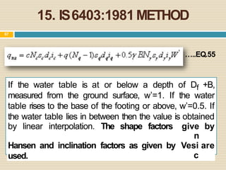
1. 15. IS6403:1981METHOD
67
…..EQ.55
If the water table is at or below a depth of Df +B,
measured from the ground surface, w’=1. If the water
table rises to the base of the footing or above, w’=0.5. If
the water table lies in between then the value is obtained
by linear interpolation. The shape factors give
n
by
Hansen and inclination
used.
factors as given by Vesi
c
are
3. 16. EFFECTOFWATERTABLEON
BEARING CAPACITY
Water in soil is known to affect its unit weight and
also the shearparameters cand φ.
When the soil is submerged under water, the
effective unit weight γ′ is to be used in the computation of
bearing capacity.
NOTE:
Effective unit weight γ′ is roughly half the saturated
unit weight; consequently there will be about 50%
reduction in the value of the corresponding term in the
bearing capacity formula.
69
4. •If the water table isat the level of the base of the footing,
γ′ isto be usedfor γ in the third term, a reduction factor
of 0.5 isto be applied to the third term.
•For any location of the water table intermediate
between the base of the footing and a depth equal to
the width of the footing below its base, a suitable linear
interpolation of the necessaryreduction is suggested.
third term
• If the water table is above the base of the
is
footing, the reduction factor for the
obviously limited to the maximum of 0.5.
5. •The maximum reduction of 0.5 is indicated for the
second term when the water table is at the ground level
itself (or above it), since γ′ is to be used for γ in the
second term.
•While no reduction in the secondterm is required when
the water table isat or below thebase of thefooting,
•Inthe caseof purely cohesivesoils,sinceφ ≈ 0°,
Nq= 1 andNγ = 0,
•Net ultimate bearing capacity isgiven by c.Nc, which
isvirtually unaffected by the water table, if it is below
the base of the footing.
6. For locations of ground water table within a depth of the
width of the foundation below the base and the ground
level, the equation for the ultimate bearing capacity may
be modified as follows:
...(Eq. 56)
*appropriate multiplying factor shouldbe usedfor isolated footings.
**Appropriate shape factor.
• If the water table isat the groundlevel, only the
gross bearing capacity is reduced by 50% of the
surcharge term γ.Df (Nq = 1), while the net value is again
only c. Nc.
• Inthe caseof purely cohesionlesssoils, since
c= 0, andφ > 0, andNqandNγ are significantly high,
8. ...(Eq. 57)
...(Eq. 58)
Note.
•Forzq> Df(the water table isbelowthebaseof the
footing), Rqislimitedto1.0.
•For0 ≤ zq≤ Df(the water table isabovethebase of the
footing), Rγislimitedto0.5.
•for zq> (Df+ b)or zγ > b,Rqaswell asRγare
limitedto1.0.
•Forzq= 0, Rqaswell asRγare limitedto0.5.
9. 18. CONTACTPRESSURE
‘Contact pressure’isthe actual pressuretransmitted from the foundation
to the soil.
Auniformly loaded foundation will not necessarily transmita uniform
contact pressure to the soil. This is possibleonly if the foundation is
perfectly ‘flexible’;
89
10. 19. PLATELOAD TEST
test essentially consists in loading
level, increasing the load in arbitrary increments,
The
foundation
determining the settlements corresponding to each load after
a rigid plate at the
and
the
settlement hasnearly ceased eachtime a load increment isapplied.
The nature of the load applied may be gravity loading or dead
weights on an improvised platform or reaction loading by using a
hydraulic jack. Thereaction of the jack load is taken by a cross beam or a
steel trussanchored suitably at both ends.
T
estplates are usually square or circular, the sizeranging from 300
to 750 mm(side or diameter); the minimumthicknessrecommended is 25
mmfor providing sufficient rigidity.
Jack-loading issuperior in termsof accuracy and uniformity of
loading. Settlementof the test plate ismeasured by meansof at least two
or three dial gaugeswith a least countof 0.02 mm.
90
12. Thetest pit should be at least five times as wide asthe test plate and the
bottom of the test plate should correspond to the proposed foundation
level. At the centre of the pit, a small square hole is made the size being
that of the testplate and the depth being suchthat,
...(Eq. 64)
13. Bigger sizeplates are preferred in cohesivesoils.Thetest procedure is
given in IS:1888–1982 (Revised).Theprocedure, in brief, isasfollows:
(i)After excavating the pit of required size and levelling the base, the test
plate is seated over the ground. Alittle sand may be spread below the
plate for even support. If ground water is encountered, it should be
lowered slightly below the base by meansof pumping.
(ii)A seating pressure of 7.0 kN/m2 (70 g/cm2) is applied and released
before actual loading is commenced.
(iii)The first increment of load, say about one-tenth of the anticipated
ultimate bearing capacity, is applied. Settlements are recorded with the
aid of the dial gauges after 1 min., 4 min., 10 min., 20 min., 40 min.,
and 60 min., and later on at hourly intervals until the rate of settlement
islessthan 0.02 mm/hour,or at least for 24 hours.
14. (iv) Thetest is continued until a load of about 1.5 times the anticipated
ultimate load is applied. According to another school of thought, a
settlement at which failure occurs or at least 2.5 cms should be
reached.
(v) Fromthe results of the test, a plot should be made between pressure
and settlement, which is usually referred to as the ‘‘load- settlement
curve’’, rather loosely. The bearing capacity is determined from this
plot, whichisdealt with in thenext
subsection.
Load-Settlement Curves
Load-Settlement curves or pressure-settlement curves to be
more precise, are obtained as a result of loading tests either in the
laboratory or in the field, oedometer tests being an example in the
laboratory and plate bearingtest,in the field.
15. Curve I is typical of dense
sandor gravelor stiffclay,
wherein general shear
failureoccurs.
Curve II is typical of loose
sand or soft clay, wherein
localshearfailure occurs.
Curve III is typical of
many c – φ soils which
exhibit characteristics
intermediate between the
above two.
16. Determination of bearing capacity from plate load test
(Terzaghi and Peck, 1948):
...(Eq. 65)
S= settlementof theproposed foundation (mm),
Sp= settlementof thetestplate(mm),
b = sizeof theproposedfoundation (m), and
bp = sizeof thetestplate (m).
Thisisapplicable for sands.
17. Therelationship issimpler for clays,sincethe modulus value
Es,for claysisreasonably constant:
...(Eq. 66)
Sp= Settlementof a testplate of 300 mmsquaresize, and
S= Settlementof a footing of width b.
The method for the determination of the bearing capacity of a footing
of width b should be apparent now. The permissible settlement value,
such as 25 mm, should be substituted in the equation that is applicable
(Eq.50 to 51) ; and the Sp,thesettlementof theplate mustbe calculated.
From the load-settlement curve, the pressure corresponding to the
computed settlement Sp, is the required value of the ultimate 9
b7earing
capacity,qult, for thefooting.
18. Limitations of Plate Load Tests
(i)Size(plate) effectsare veryimportant.
(ii)Consolidation settlementsincohesivesoils,whichmaytake
years,cannotbe predicted,
(iii)Resultsfrom plate load testare not recommendedto be
usedfor thedesignof stripfootings,
(iv)The load test results reflect the characteristics of the soil
located only within a depth of about twice the width of the
plate.
Thus,it may be seenthat interpretation and useof the plate
load test results requires great care and judgment, on the
part of the foundation engineer.
19. 20. BEARINGCAPACITYFROM
PENETRATION TESTS
Terzaghi and Peck have prepared charts for allowable
bearing pressure, based on a standard allowable
settlement, for footings of knownwidths onsand, whose N-
valuesareknown.
99
20. obtainedfromthe charts.
Above figures do not apply to gravels or those soils containing a large
percentage of gravels. These charts have been prepared on the
assumption that the water table is at a depth greater than the width of
the footing below the base of the footing. If the water table is located at
t
1
h
0
e
0 baseof thefooting, the allowable pressureistaken ashalf that
21. Charts given by Peck, Hanson and Thornburn (1953) may be used
for the determination of allowable bearing pressure for a specific
allowable settlement of 25 mmor 40 mm,
Fig.1 allowable bearing pressure
for 40mm settlement.
Fig.2 allowable soil pressure
22. Teng(1969) hasproposed the following equation for the graphical
relationship of Terzaghi and Peckfor a settlement of 25 mm:
...(Eq. 67)
where qna= netallowable soil pressurein kN/m2 for a settlement
of 25 mm,
N = Standard penetration valuecorrectedfor overburdenpressure
andother applicable factors,
b = width of footing in metres,
Rγ= correction factor for location of water table, (Eq.56)
and Rd= Depthfactor (= 1 + Df /b) ≤ 2.
whereDf = depthof footing inmetres.
Themodified equation of T
engisasfollows:
...(Eq.68)
23. Meyerhof (1956) has proposed slightly different equations for a
settlement of 25 mm, but these yield almost the same results as T
eng’s
equation:
...(Eq.69)
...(Eq.70)
Modified equation of Meyerhof isas follows:
...(Eq.71)
...(Eq.72)
24. TheI.S.codeof practice gives Eq.73 for a settlementof 40 mm;but,
it doesnot consider the depth effect.
...(Eq. 73)
...(Eq.73a)
qna= netallowable soil pressureinkN/m2 for a settlement of
25 mm,
N = Standard penetration value corrected for
overburden pressureandother applicablefactors,
b = width of footing inmetres,
Rγ= correction factor for location of water table, (Eq.52)
Rd= Depthfactor (= 1 + Df /b) ≤ 2.
Df = depthof footing in metres.
25. Teng(1969) also givesthe following equations for bearing
capacityof sandsbased onthe criterion of shearfailure:
...(Eq. 74)
...(Eq. 75)
N = Standard penetration value, after applying the necessary
corrections,
b = width of continuous footing (side, if square, and diameter, if
circular in metres),
Df = depthof footing in metres,and
RγandRq= correction factors for theposition of theground water
table, defined in Eqs.52 & 53.
27. QUICK NOTE
Skempton’s equations are preferred for rectangular footings in pure
clay.
Correlation of cohesion and consistency of clays with N-values is not
reliable. Unconfined compression test is recommended for evaluating
cohesion.
Overconsolidated or precompressedclays might showhair cracksand
slickensides.Load testsare recommended in suchcases.
Settlementsof footings in clays maybe calculated or predicted by the
useof Terzaghi’sone-dimensionalconsolidation.
Thebearing capacity of footings in clays ispractically unaffected by
the sizeof thefoundation.
28. Example1: Compute the safe bearing capacity of a square footing 1.5 m
× 1.5 m, located at a depth of 1 mbelow the ground level in a soil of
average density 20 kN/m3. φ = 20°, Nc = 17.7, Nq = 7.4, and Nγ
= 5.0. Assumea suitable factor of safety and that the water table is very
deep. Also compute the reduction in safe bearing capacity of the
footing if the water table risesto the ground level.
b = 1.5 mSquarefooting Df = 1 m
γ= 20 kN/m3 φ = 20° Nc= 17.7, Nq = 7.4, andNγ =5.0
Assumec= 0 andη = 3
qult = 1.3 cNc+ 0.4 γ b Nγ +γDf Nq = 0.4 γ b Nγ +γ Df Nq, in this
case.
= 0.4 × 20 × 1.5 × 5.0 + 20 × 1 × 7.4 = 60 + 148 = 208 kN/m2
qnetult = qult – γ Df = 208 – 20 × 1 = 188 kN/m2
30. Example2:Aplate load testwasconductedona uniform depositof sand
andthefollowing data wereobtained:
(i)Plot thepressure-settlementcurveanddeterminethefailure stress.
(ii)A square footing, 2m × 2 m, is to be founded at 1.5 mdepth in this
soil. Assuming the factor of safety against shear failure as 3 and the
maximum permissible settlement as 40 mm, determine the allowable
bearing pressure.
(iii) Designof footing for a load of 2,000 kN, if thewater table isat
a great depth.
31. (i) The pressure-settlement curve is shown in Fig. Thefailure point is
obtained asthe point corresponding to the intersection of the initial
and final tangents. Inthiscase,the failure stressis500kN/m2.
∴qult = 500 kN/m2
32. (ii) Thevalueof qult hereisgiven by
0.5.γbp Nγ .
bp, thesizeof testplate = 0.75 m
Assumingγ= 20kN/m3,
500 = 0.5 × 20 × 0.75Nγ
∴Nγ =500/7.5 ≈ 6.7
φ = 38°
∴Nq ≈ 50 from Terzaghi’s charts.
Forsquare footing of size2 mand Df = 1.5 m,
qnetult = 0.4 γ b Nγ +γDf (Nq –1)
= 0.4 × 20 × 2 × 67 + 20 × 1.5 × 49 = 2,542 kN/m2
qsafe= 2542/3 ≈ 847 kN/m2 (for failure againstshear)
33. Pressure for a settlement of 27 mm for the plate (from Fig. ) = 550
kN/m2. Allowable bearing pressure is the smaller of the values from
the two criteria = 550 kN/m2.
(iii) Designload = 2,000kN
FromPart (ii), it isknownthat a 2 msquarefooting cancarry a load of
2 × 2 × 550 = 2,200 kN.
Therefore, a 2 m square footing placed at a depth of 1.5 m is
adequate for thedesignload.
34. 114
Example3 (ESECE2017)
In a plate load test on a soil, at a particular magnitude of the
settlement, it was observed that the bearing pressure beneath the footing
is 100 kN/m2 and the perimeter shear is 25 kN/m2. Correspondingly, the
load capacity of a 2msquare footing at the samesettlement will be
(a) 200 kN
(c)400kN
(b) 300 kN
(d) 600 kN
Sol.
Q = Aσb + Pσs
σb = Bearingpressure
σs= Perimetershear
A= Plate base area
P= Perimeter
Q = Loadcapacity
Q = 2 × 2 × 100 + 2 × 4 × 25
Q = 600 kN
35. GATE2018 :Thecontactpressureand settlementdistribution
for a footing are shownin the figure. Thefigure correspondsto
a
(a) rigid footing ongranular soil
(b) flexible footing ongranular soil
(c)flexible footing onsaturated clay
(d) rigid footing oncohesivesoil.
36. REFRENCES:
C. VENKATARAMAIAH
GEOTECHNICAL ENGINEERING
THIRD EDITION
( NEW AGE INTERNATIONAL (P) LTD. PUBLISHERS)
MUNI BUDHU-
SOIL MECHANICS AND FOUNDATIONS
THIRD EDITION -WILEY (2010)
A.S.R RAO & GOPAL RANJAN-
BASIC AND APPLIED SOIL MECHANICS
(NEW AGE INTERNATIONAL (P) LTD., PUBLISHERS)
IS 6401:1981 & IS: 1888–1982