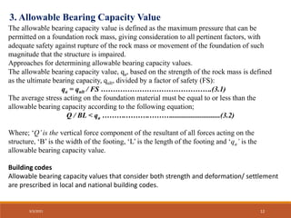
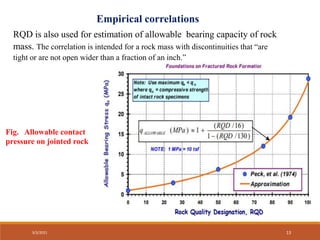
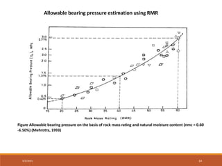
This document discusses methods for estimating the bearing capacity of rocks for foundations. It begins with definitions of ultimate and allowable bearing capacity. It then presents several equations that can be used to estimate ultimate bearing capacity based on factors like rock strength, joint spacing, and rock type. Correction factors for different foundation shapes are also provided. The document concludes by discussing approaches for determining an allowable bearing capacity value from the ultimate capacity using a factor of safety. It presents empirical correlations and guidelines from building codes for estimating allowable bearing values based on factors like rock quality designation (RQD) and rock mass rating (RMR).


(1-1/ Nφ)- Nφ(cot φ) +2 Nφ
1/2 ……………….2.12
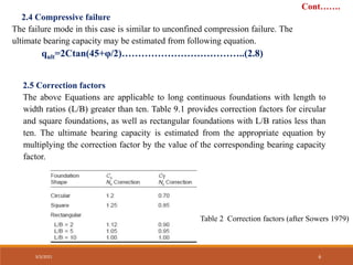
Cont…….
3/3/2021 7](https://image.slidesharecdn.com/bearingcapacityestimationpresentationtarun-210304172401/85/Bearing-capacity-estimation-rocks-for-foundation-7-320.jpg)

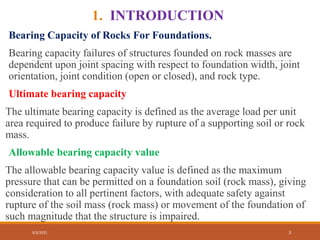
![3+S /B
Nj =
10 [1+300(δ/S)]
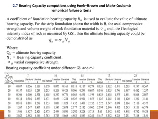
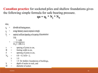
In case of rock mass with favorable discontinuities, the
net allowable bearing pressure may be estimated from:
qa = qc * Nj
Where
qc = average uniaxial compressive strength of rock cores
Nj = empirical coefficient depending on the spacing of the discontinuities
δ = thickness of discontinuity
S = spacing of discontinuities
B = width of footing
The above relationship is valid for a rock mass with spacing of continuities >
0.3 m, δ < 10 mm (15 mm if filled with soil) and B >0.3 m.
3/3/2021 15](https://image.slidesharecdn.com/bearingcapacityestimationpresentationtarun-210304172401/85/Bearing-capacity-estimation-rocks-for-foundation-15-320.jpg)


![Geotechnical Engineering-II [Lec #18: Terzaghi Bearing Capacity Equation]](https://cdn.slidesharecdn.com/ss_thumbnails/18-181123045854-thumbnail.jpg?width=640&height=640&fit=bounds)


![[LN], [Chapter3.1], Foundation Eng'g-1, Bearing Capacity of Shallow Foundatio...](https://cdn.slidesharecdn.com/ss_thumbnails/lnchapter3-251229124520-79d90b38-thumbnail.jpg?width=640&height=640&fit=bounds)


