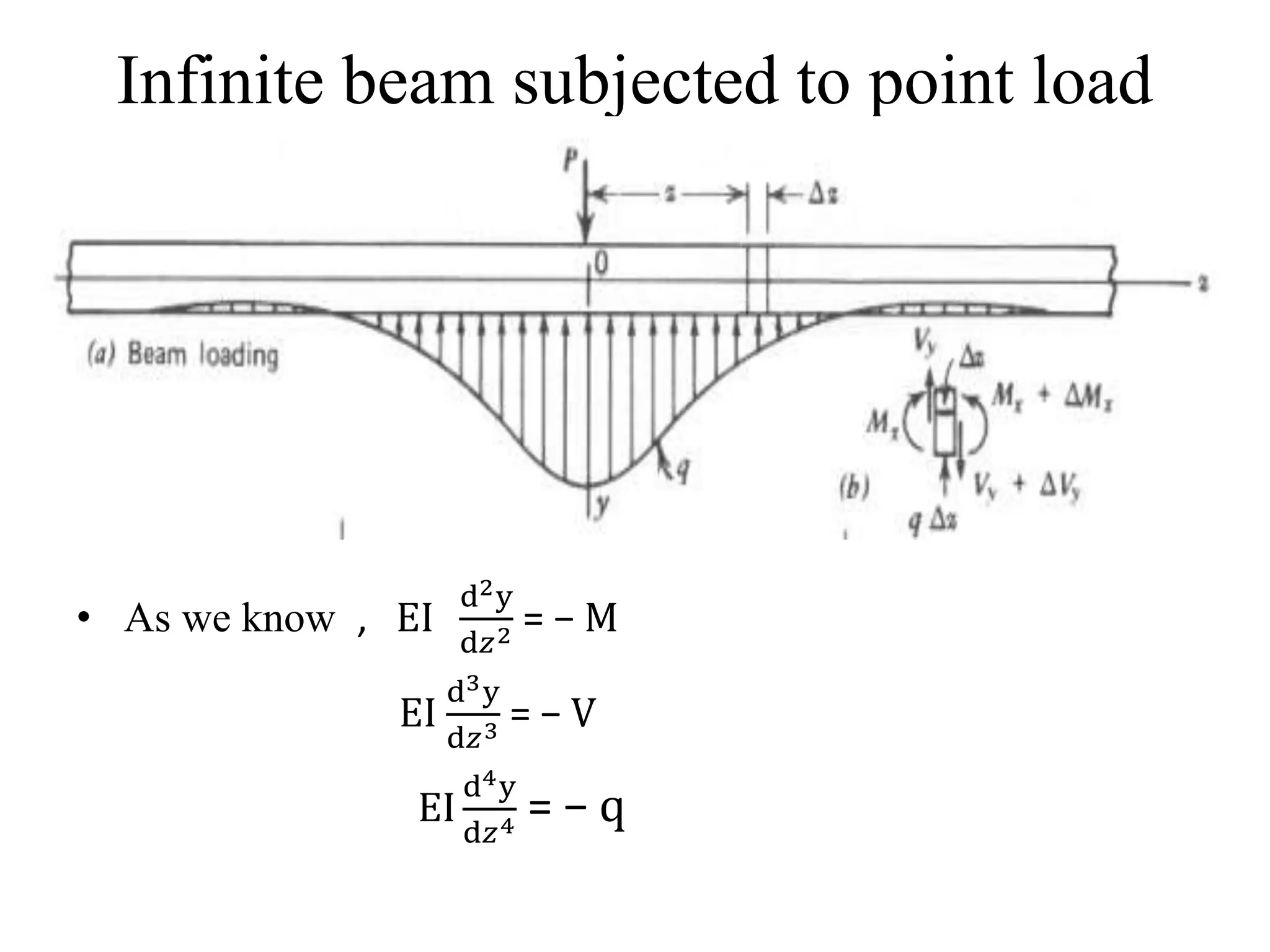
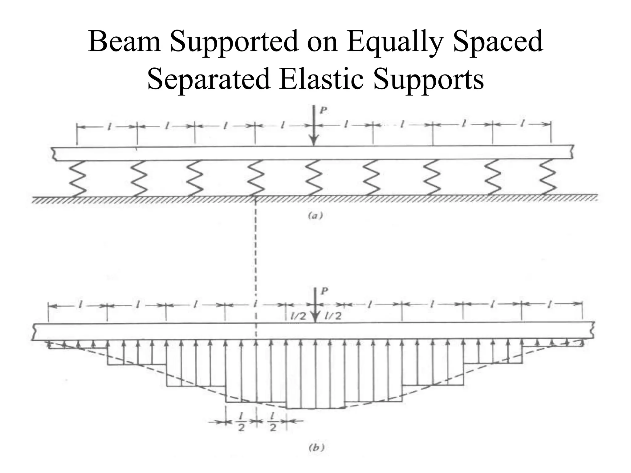
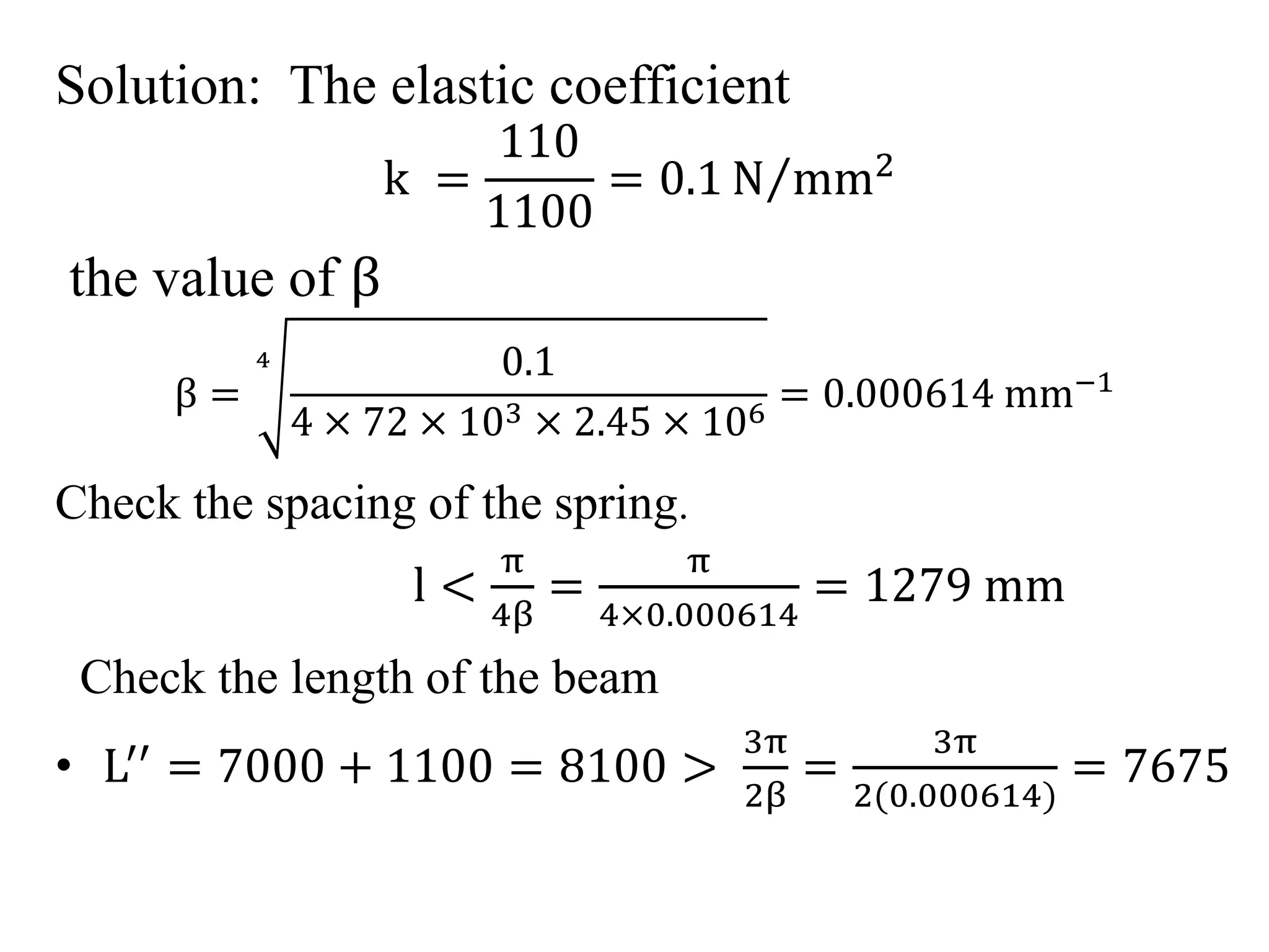
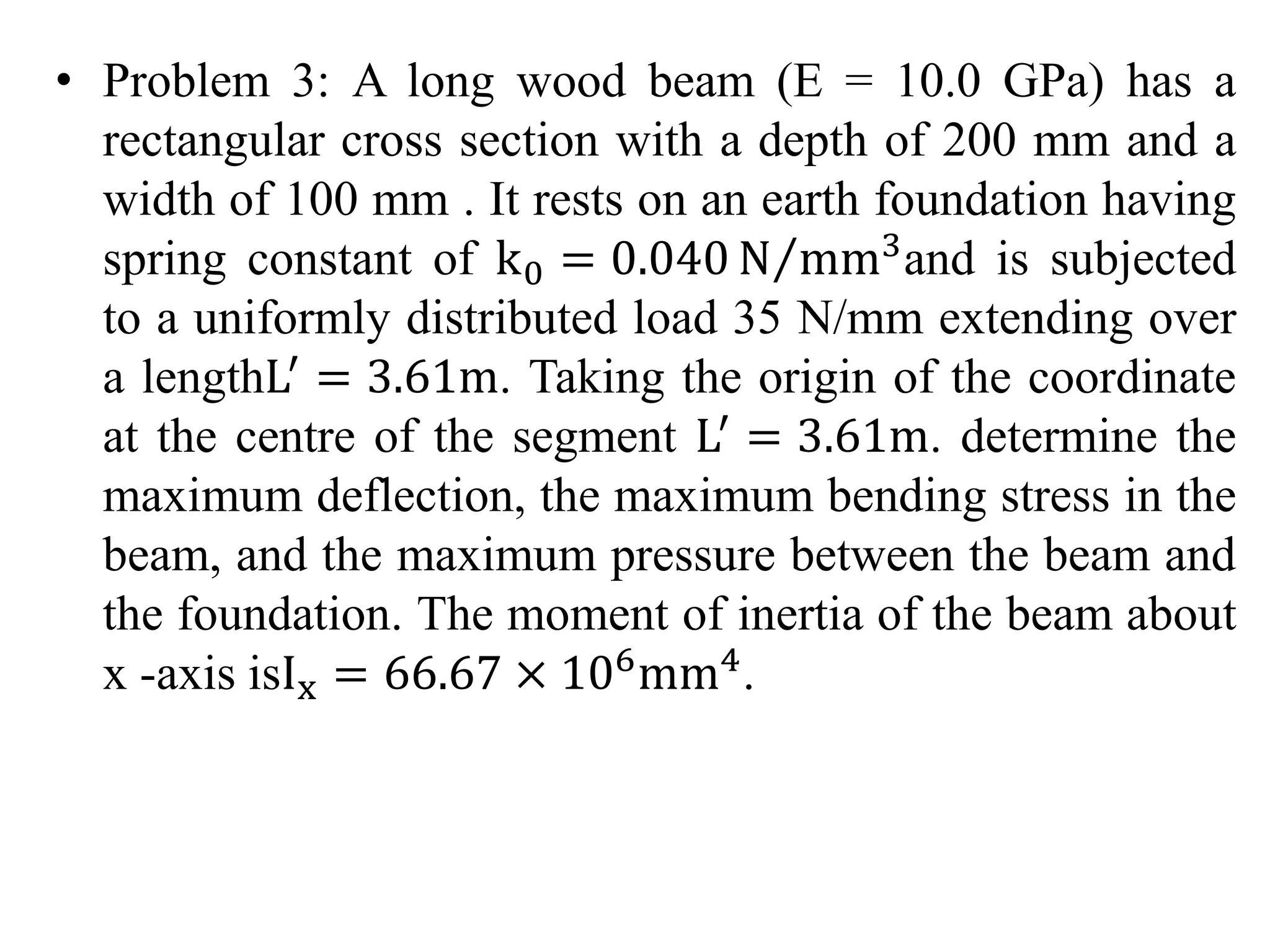
This document discusses beams supported on an elastic foundation. It begins by introducing the Winkler foundation model and defining short, medium, and long beams based on the parameter βL. It then provides solutions for the deflection, slope, bending moment and shear force of an infinite beam under a point load. The document also discusses beams supported by discrete elastic supports and beams subjected to a distributed load segment. It provides examples calculating deflection, bending stress, and pressure for specific beam problems.
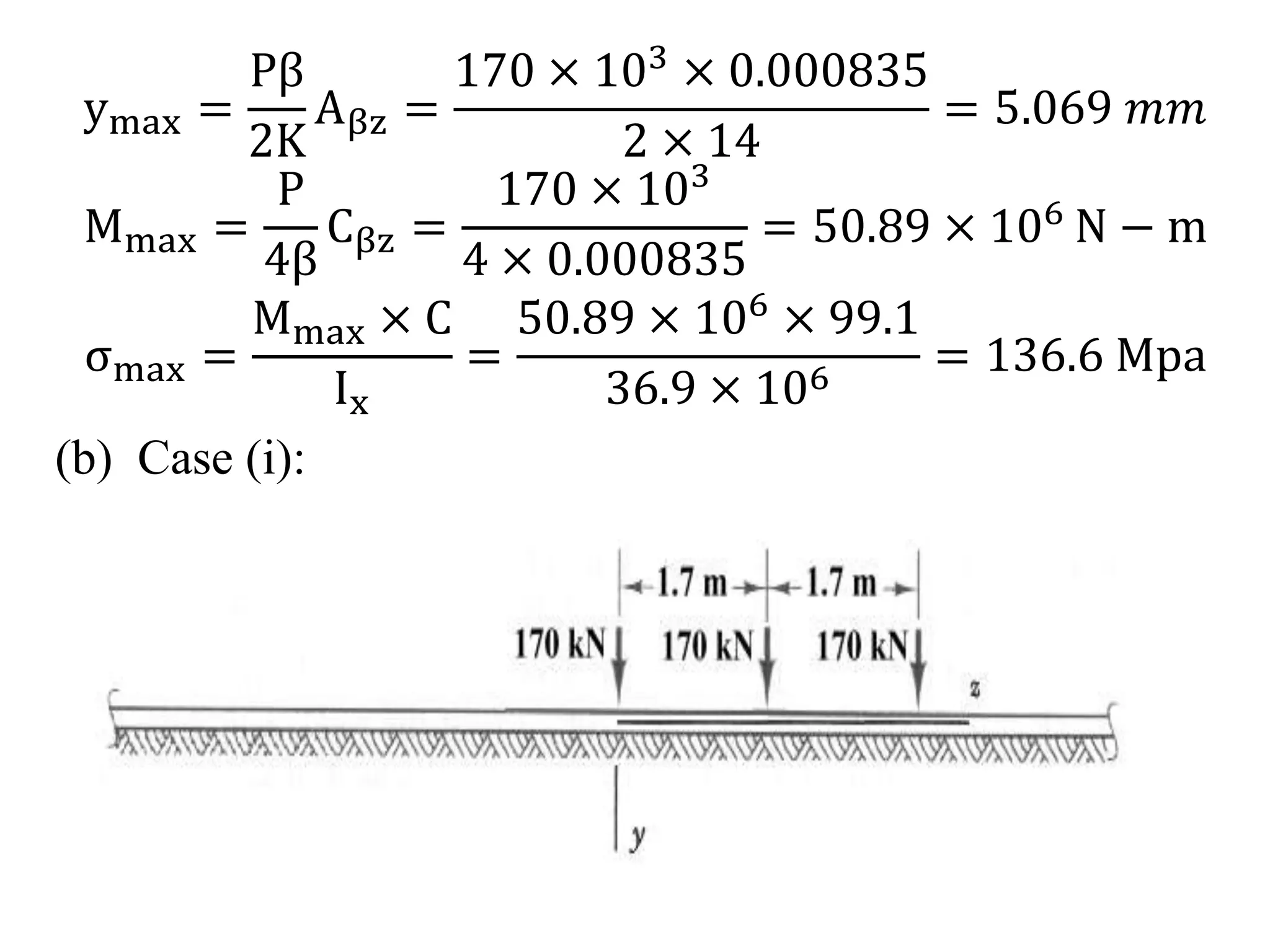
![θ =
dy
dz
=
Pβ
2K
[−2βe−βz sinβz ]
= −
Pβ2
K
[e−βz sinβz ]
Mx = −EIx
d2y
dz2 = EIx
Pβ2
K
d
dz
[e−βz sinβz ]
=
P
4β
e−βz cosβz − sinβz)
Vy = −
dM
dz
= −
d
dz
[
P
4β
e−βz cosβz − sinβz ]
=
P
2
e−βz cosβz](https://image.slidesharecdn.com/bef2-141021063641-conversion-gate01/75/Bef-2-9-2048.jpg)
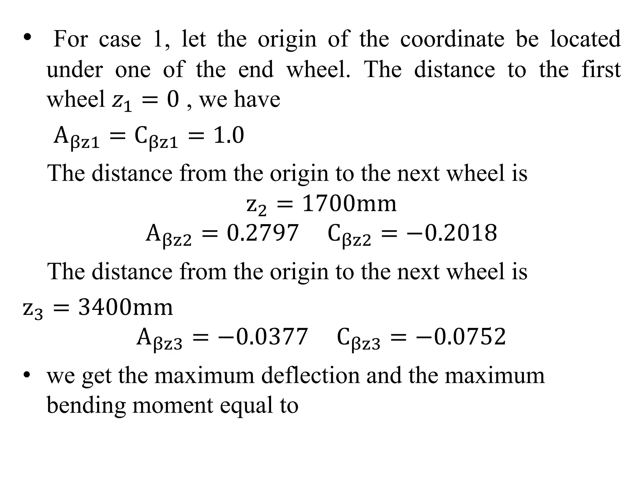
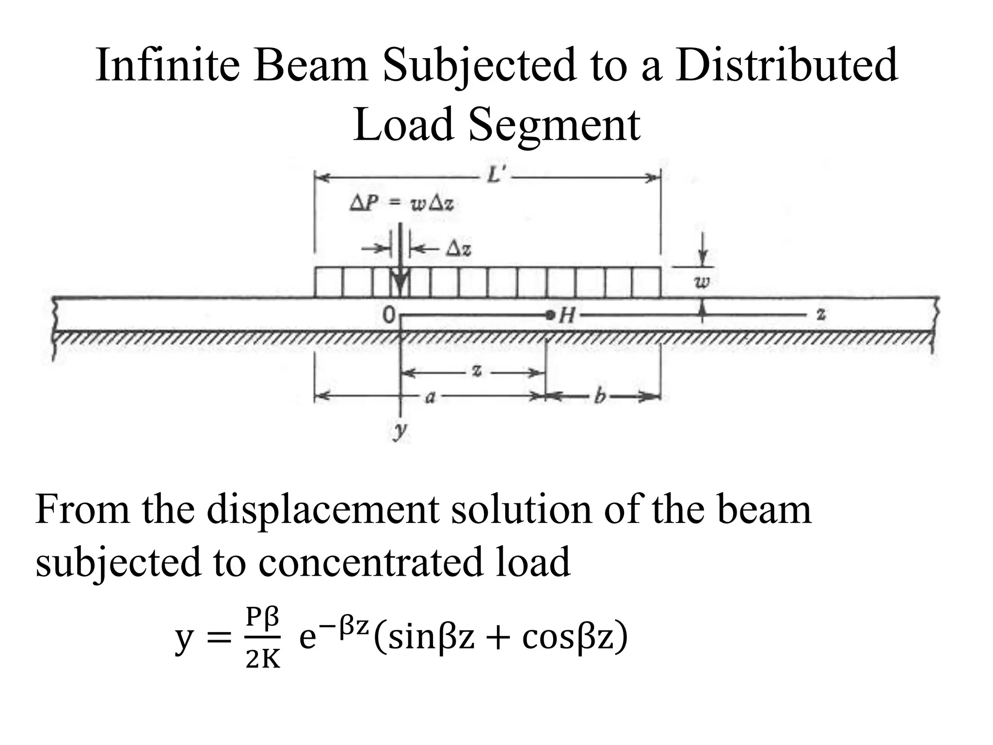
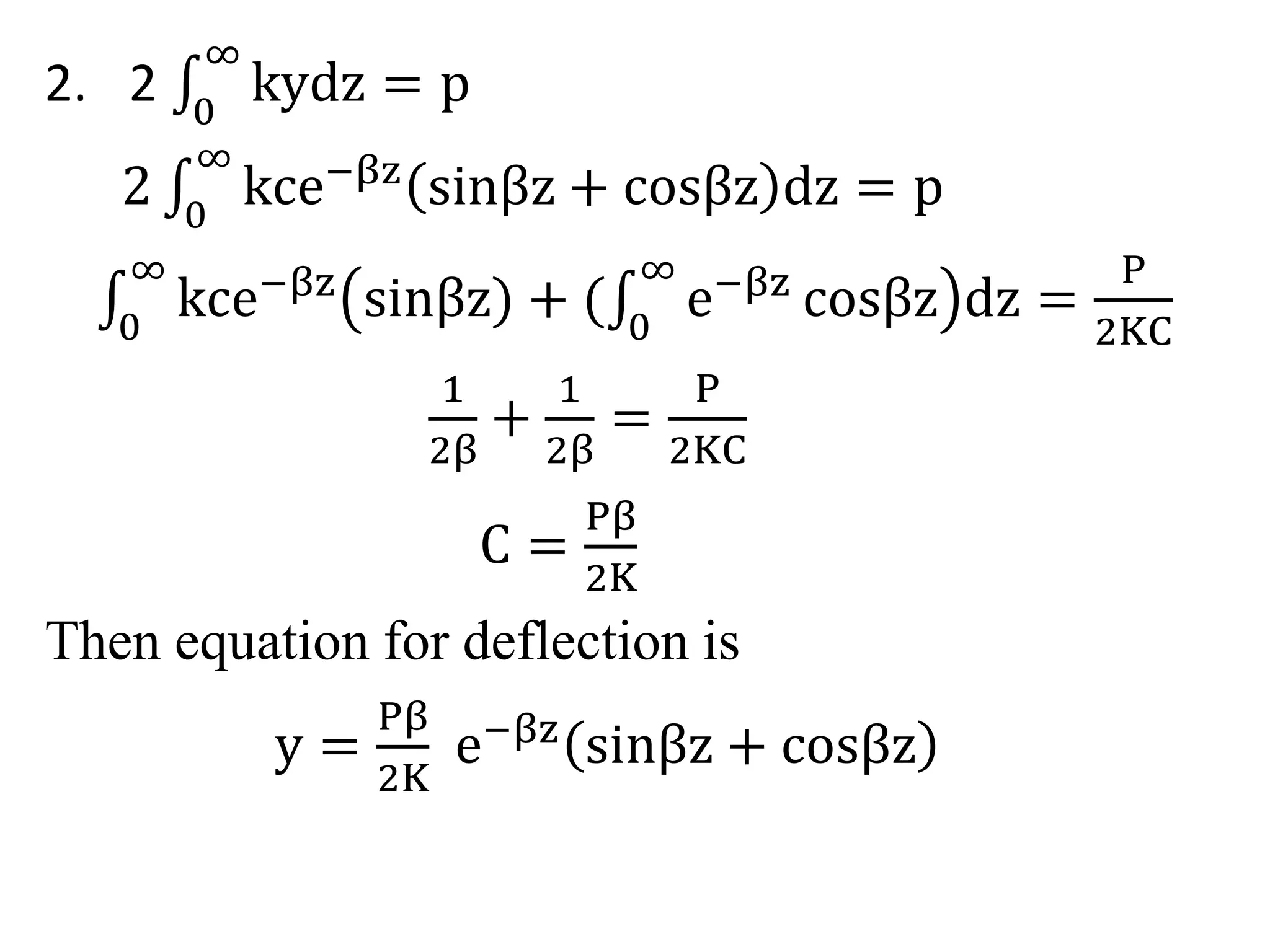
![dyh =
wβ
2K
e−βz sinβz + cosβz dz
By using the principle of superposition, the total
deflection due to the distributed load is
a wβ
yh = 0
2K
e−βz sinβz + cosβz dz +
b wβ
0
2K
e−βz sinβz + cosβz dz
yh =
wβ
2K
[
1
β
1 − e−aβcosβa +
1
β
1 − e−bβcosβb ]
=
w
2K
[2 − e−aβcosβa − e−bβcosβb]
θH =
a dyh
0
dz
dz +
b dyh
0
dz
dz =
wβ
2K
[Aβa − Aβb]
MH =
w
4β2 [Bβa + Bβb] VH =
w
4β
[Cβa − Cβb]](https://image.slidesharecdn.com/bef2-141021063641-conversion-gate01/75/Bef-2-24-2048.jpg)
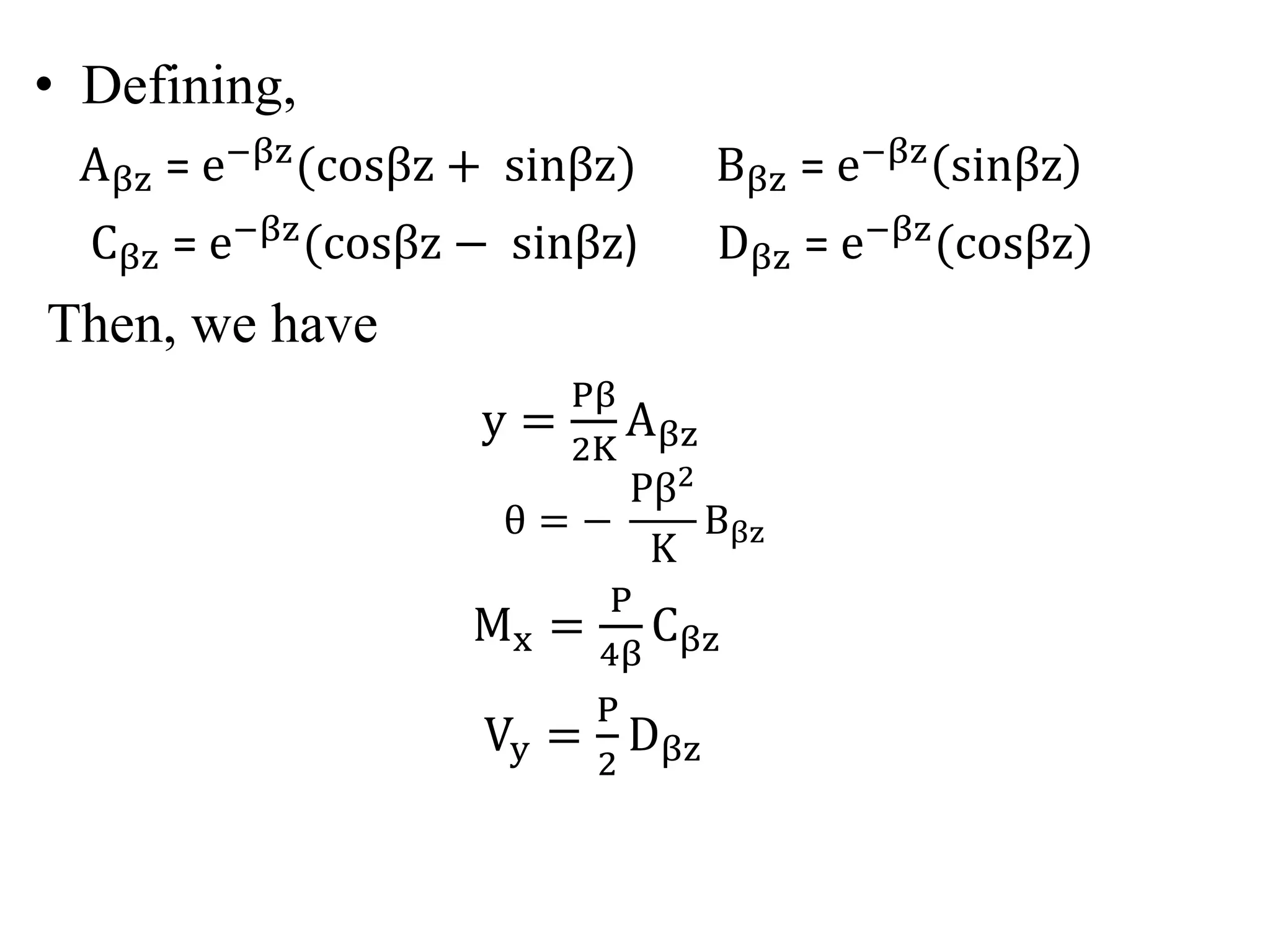
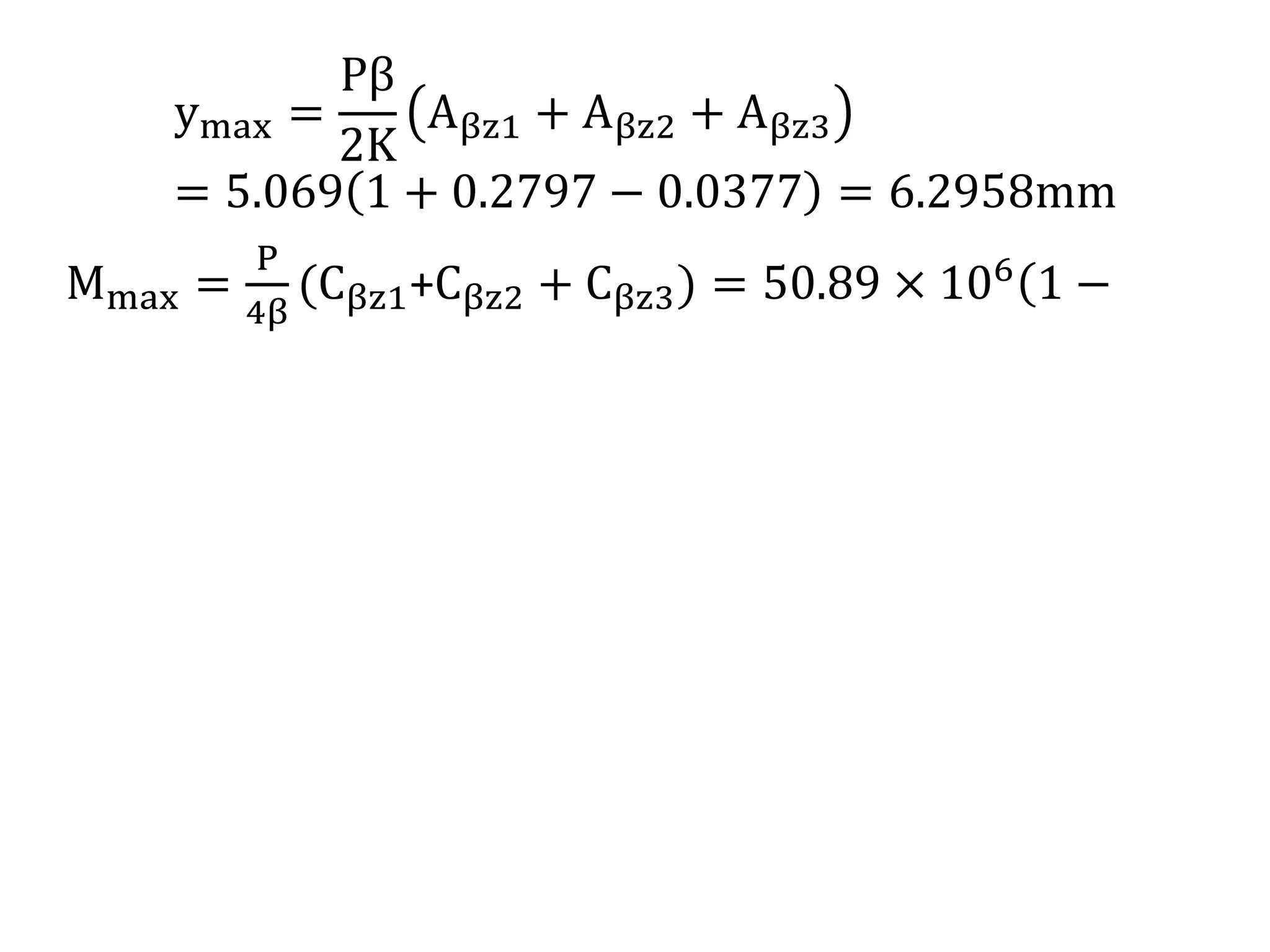
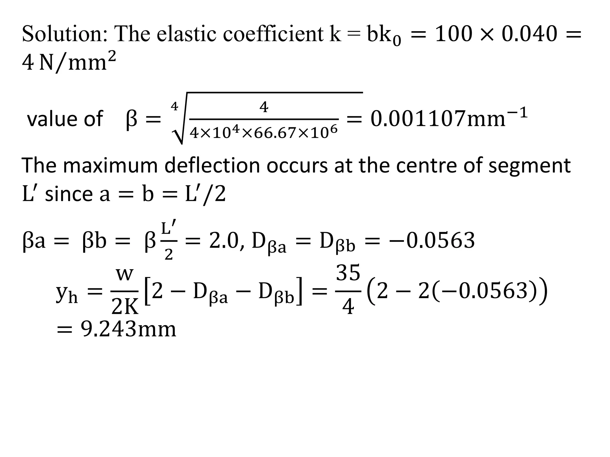
![where,
Aβa = e−aβ sinβa + cosβa) Bβa = e−aβsinβa
Cβa = e−aβ cosβa − sinβa) Dβa = e−aβcosβa
Aβb = e−bβ sinβb + cosβb) Bβb = e−bβsinβb
Cβb = e−bβ cosβb − sinβb) Dβb = e−bβcosβb
yh =
w
2K
[2 − Dβa − Dβb]
θH =
wβ
2K
[Aβa − Aβb]
MH =
w
4β2 [Bβa + Bβb]
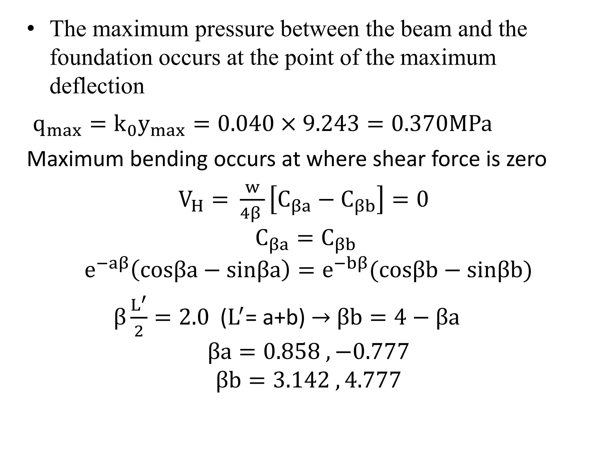
VH =
w
4β
[Cβa − Cβb]](https://image.slidesharecdn.com/bef2-141021063641-conversion-gate01/75/Bef-2-25-2048.jpg)
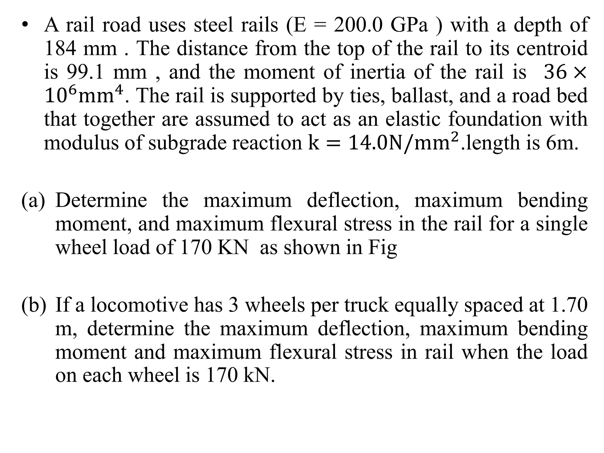
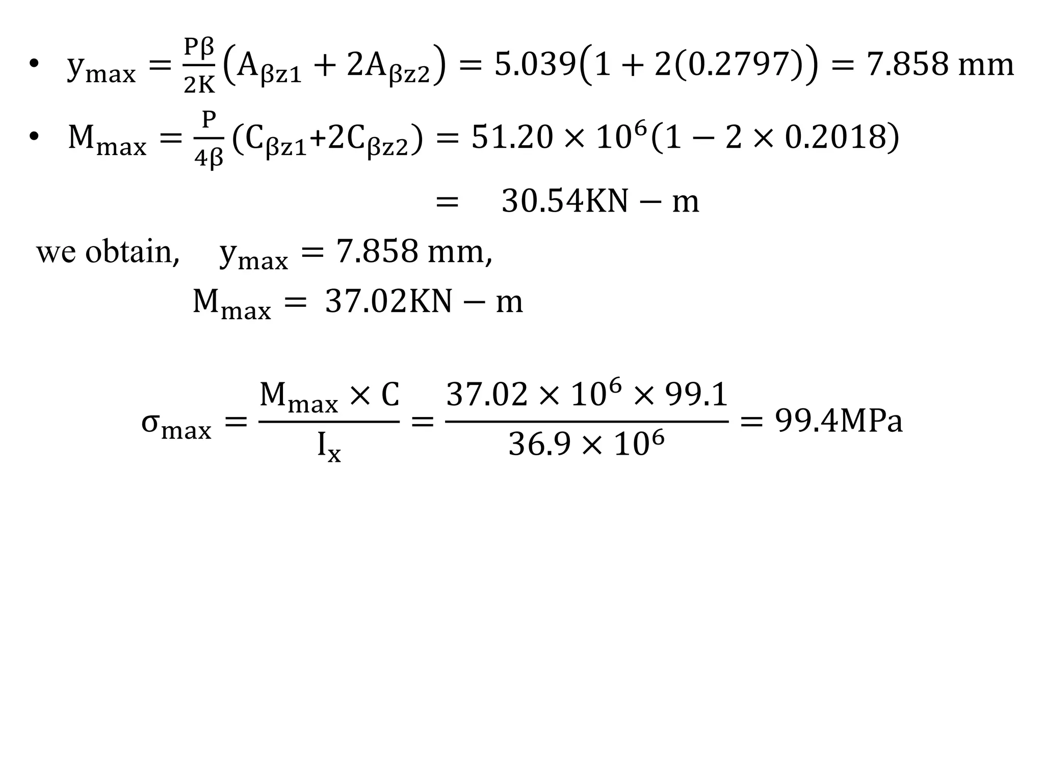
![Mmax =
w
4β2 [Bβa + Bβb]
=
35
4 0.001072)
[0.3233 + 0.0086]
= 2.363 KN-m
Bending stress is σ =
M
I
× Y = 3.544 MPa](https://image.slidesharecdn.com/bef2-141021063641-conversion-gate01/75/Bef-2-29-2048.jpg)
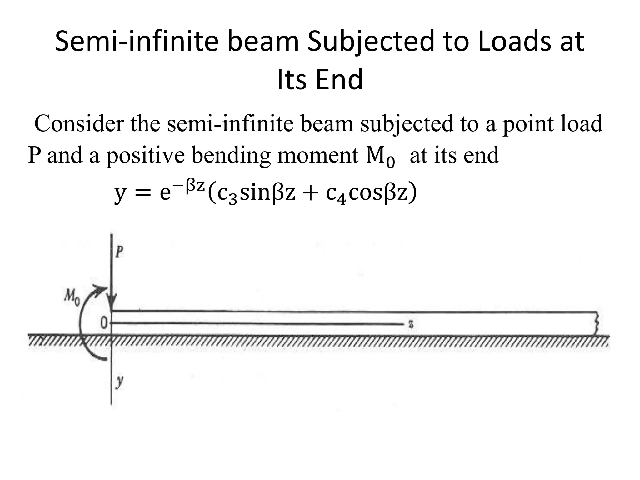
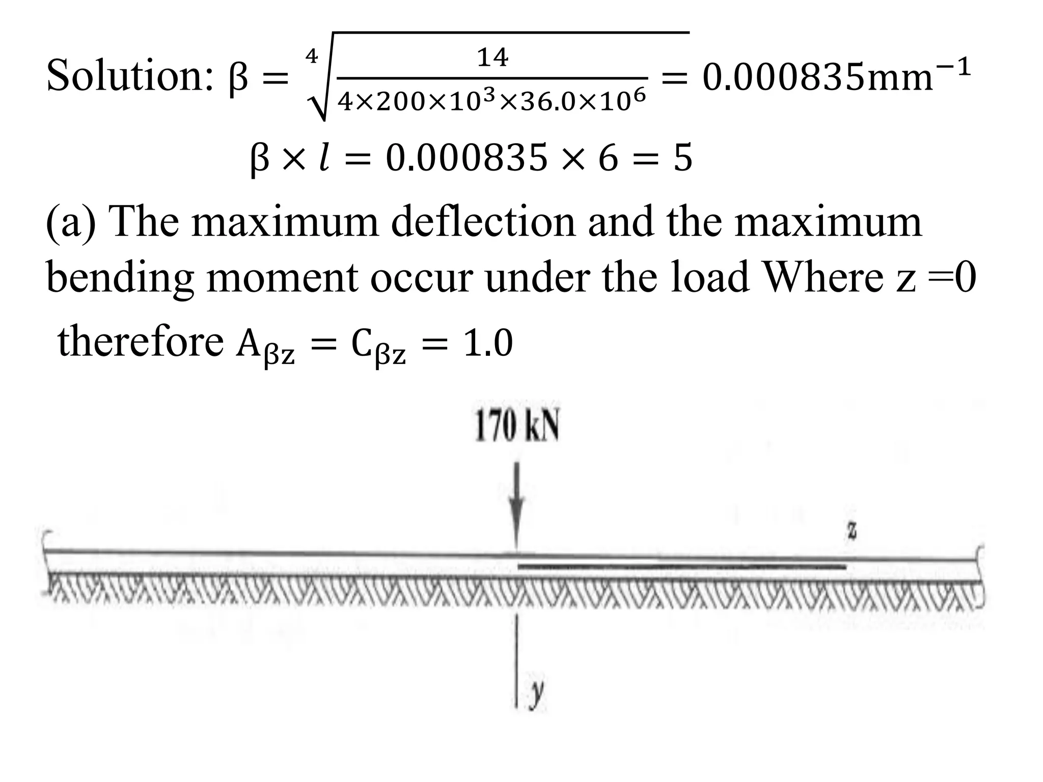
![c3,c4 can be obtained by applying boundary
conditions
EIx
d2y
dz2
z=0
= −M0
EIx
d3y
dz3
z=0
= −Vy = P
d2y
dz2 = −
2β2
eβz [c3cosβz − c4sinβz]
c3 =
M0
2β2EIx
=
2β2M0
k
d3y
dz3 =
2β3
eβz [c3sinβz + c4cosβz + c3cosβz − c4sinβz]](https://image.slidesharecdn.com/bef2-141021063641-conversion-gate01/75/Bef-2-31-2048.jpg)
![c3 + c4 =
p
2β3EIx
=
2βP
k
c4 =
2βP
k
−
2β2M0
k
the deflection of the beam is
y =
2βe−βz
k
[Pcosβz − βM0 cosβz − sinβz)]
By rearranging, y =
2βP
k
Dβz −
2β2M0
k
Cβz
θ = −
2Pβ2
K
Aβz +
4β3M0
k
Dβz
Mx = −
P
β
Bβz + M0 Aβz
Vy = −PCβz − 2M0β Bβz](https://image.slidesharecdn.com/bef2-141021063641-conversion-gate01/75/Bef-2-32-2048.jpg)