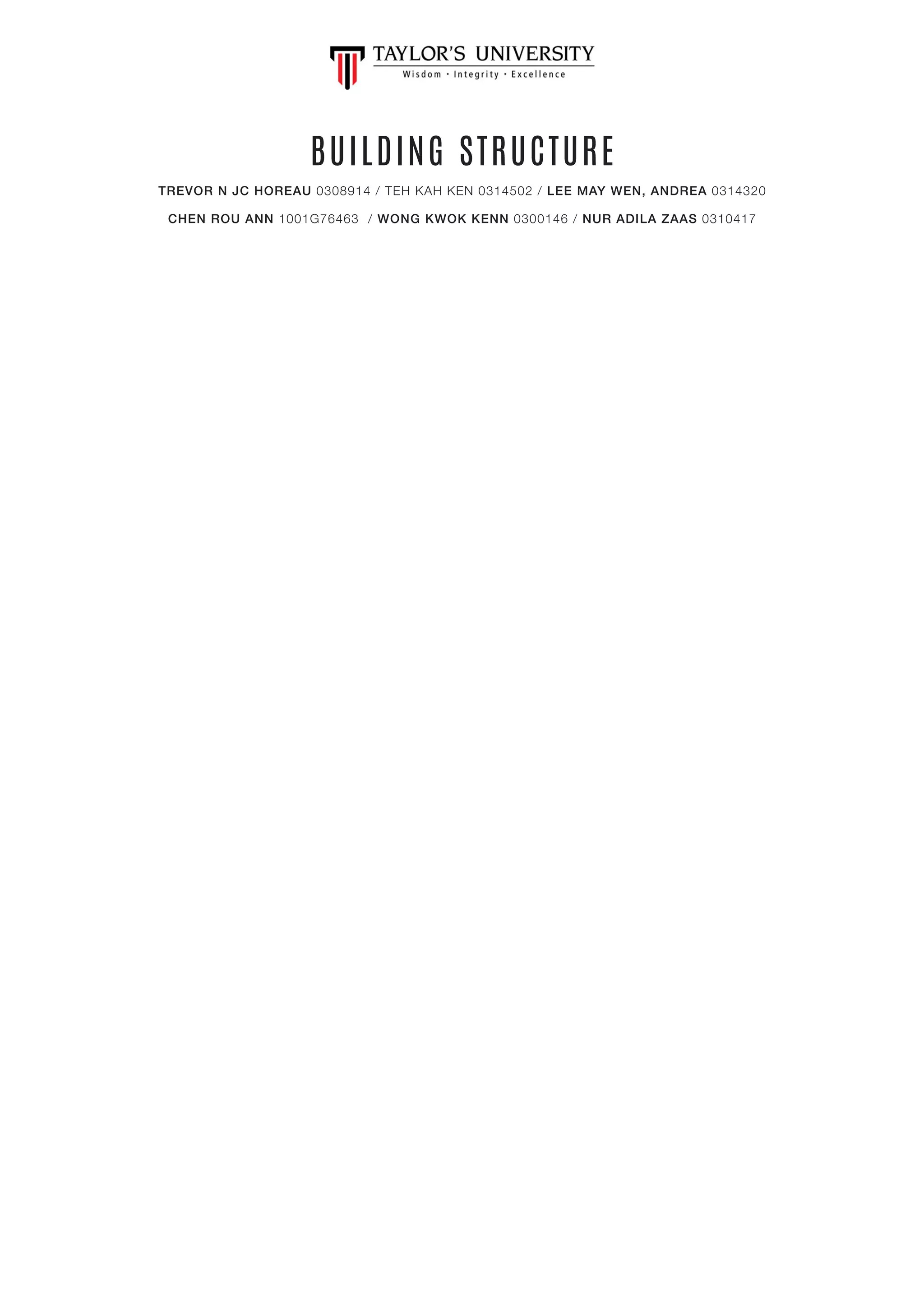
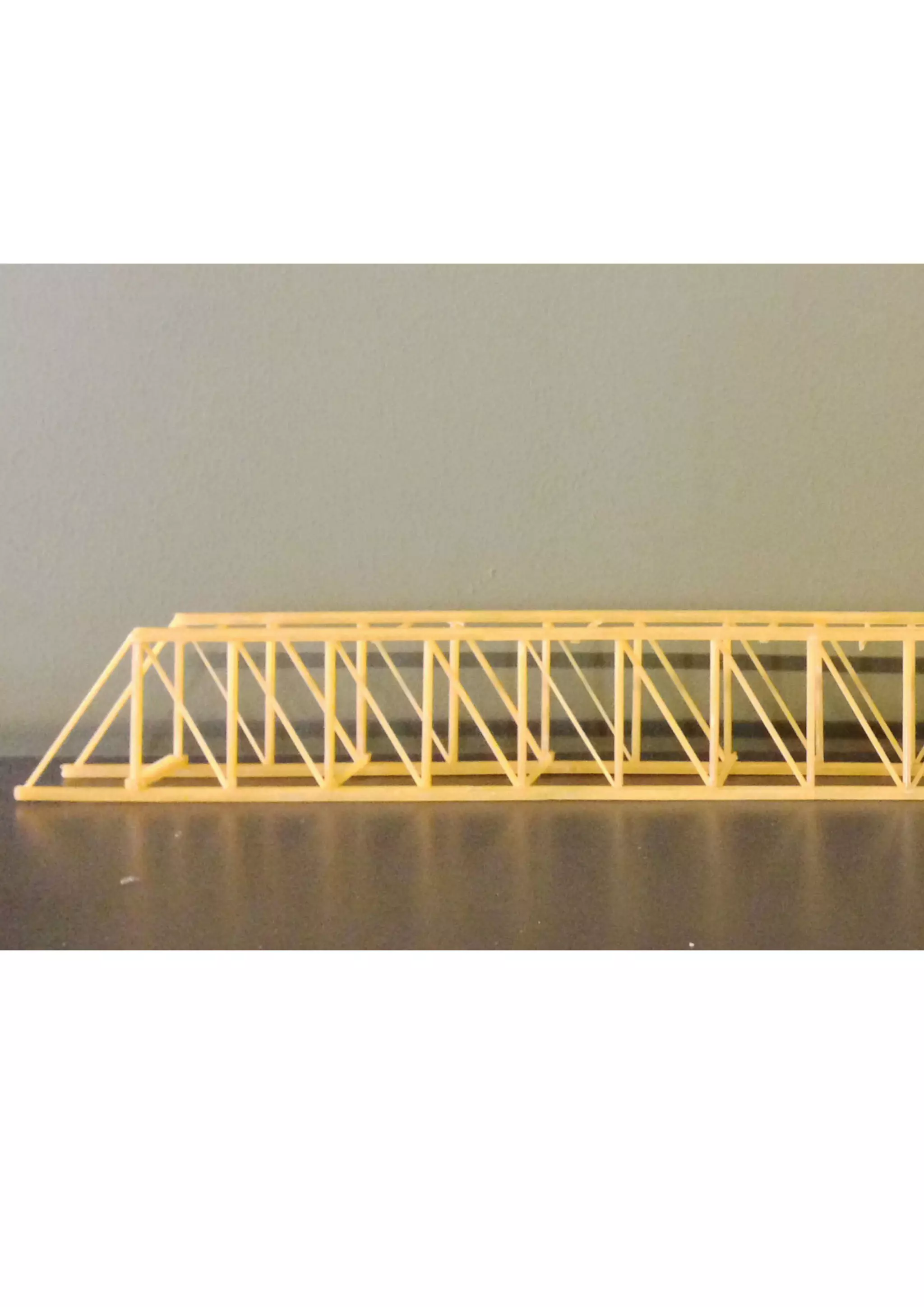
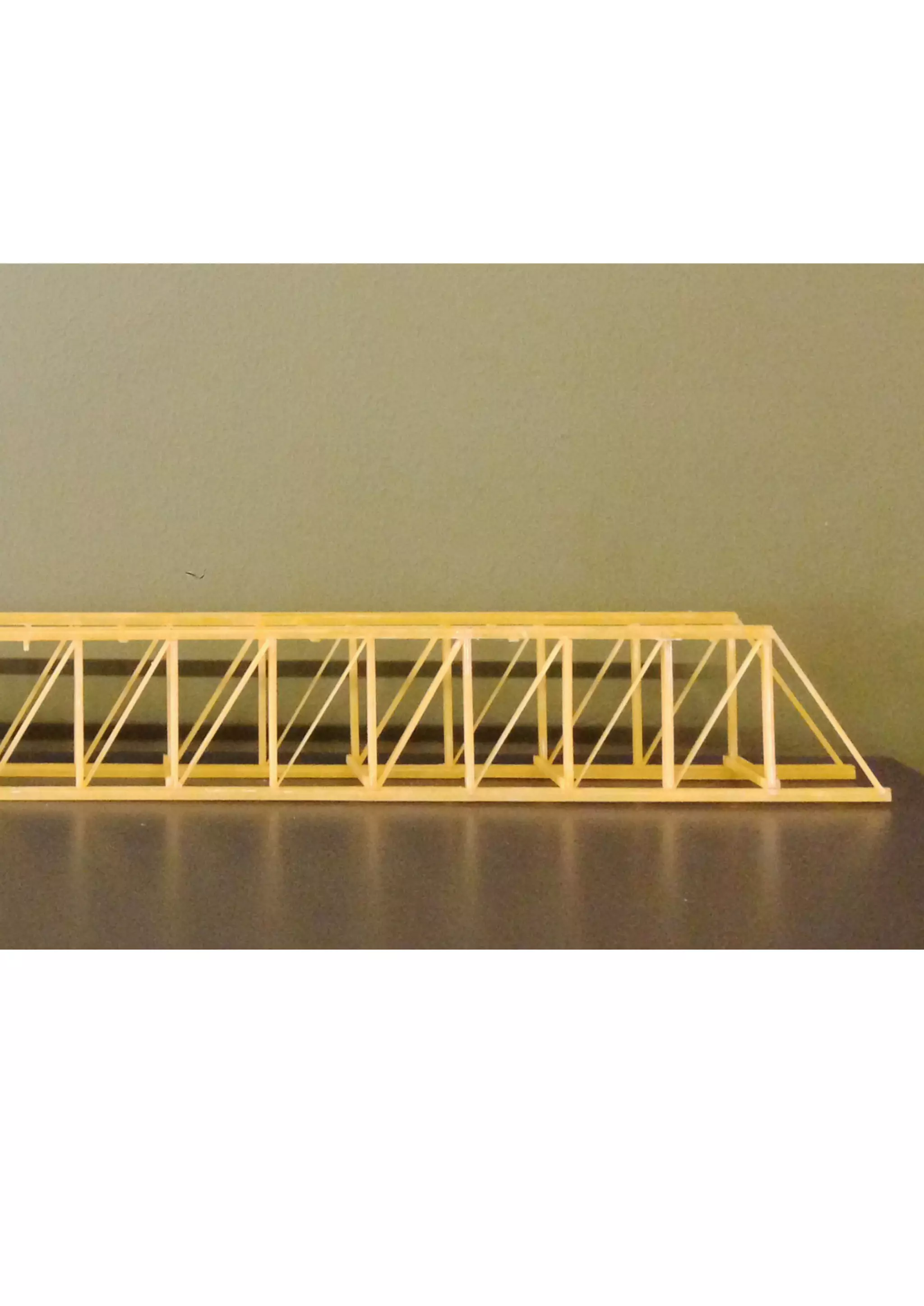
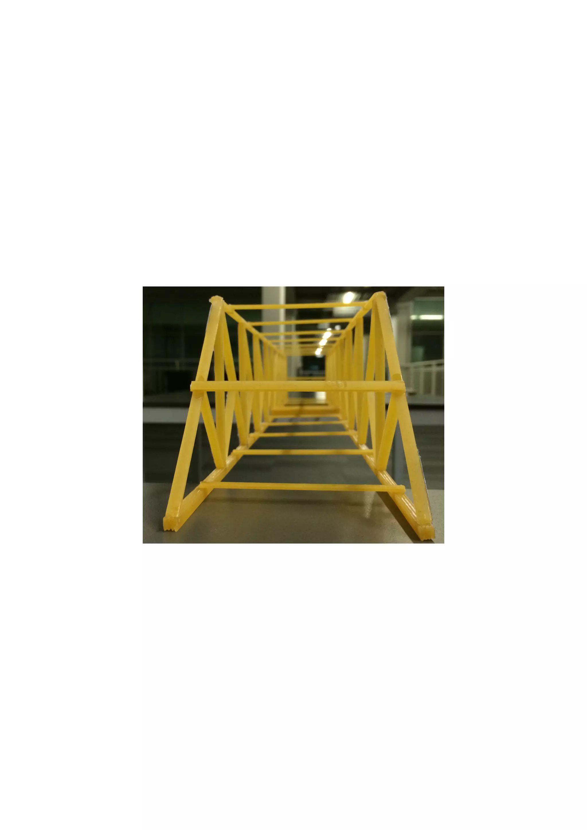
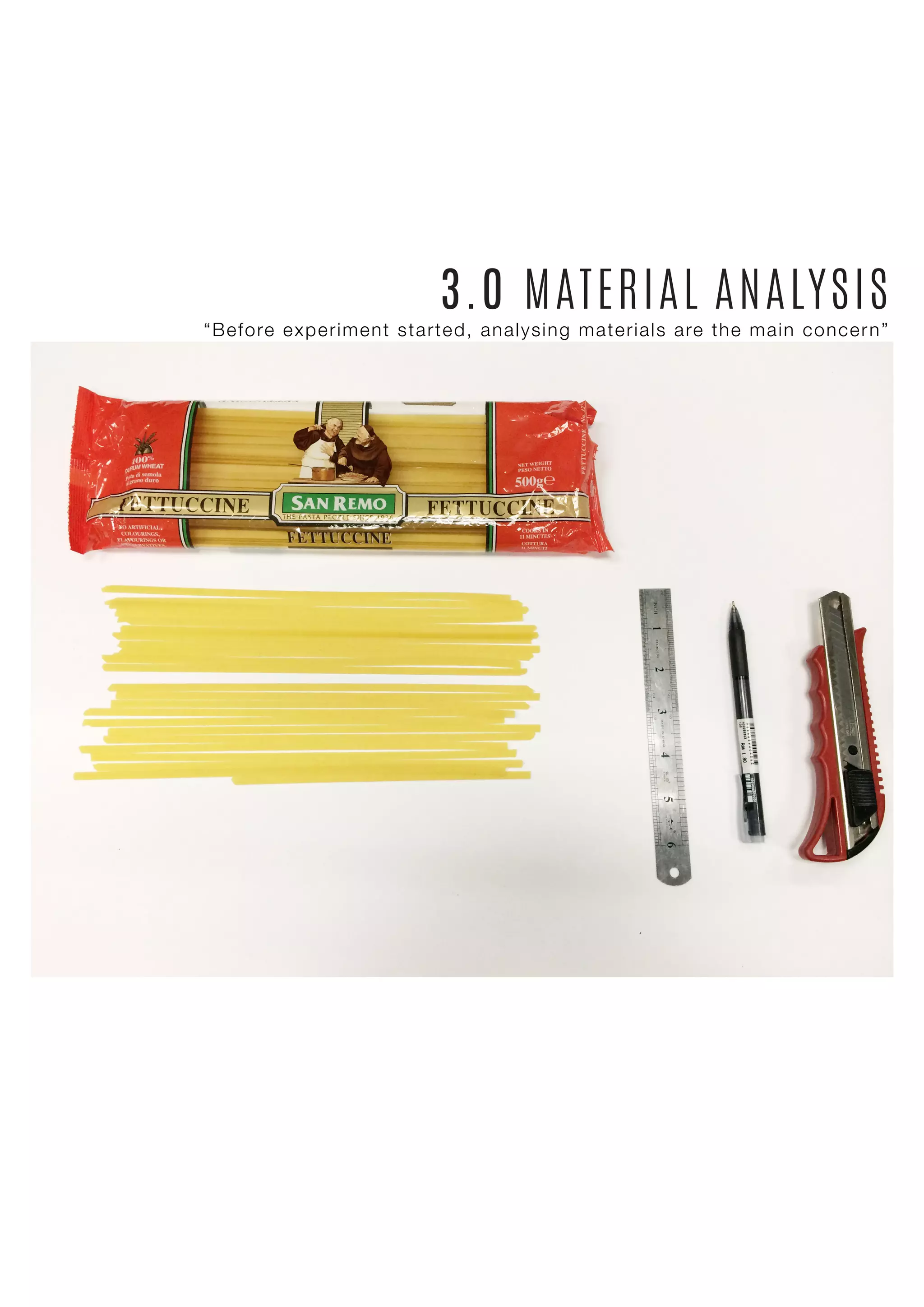
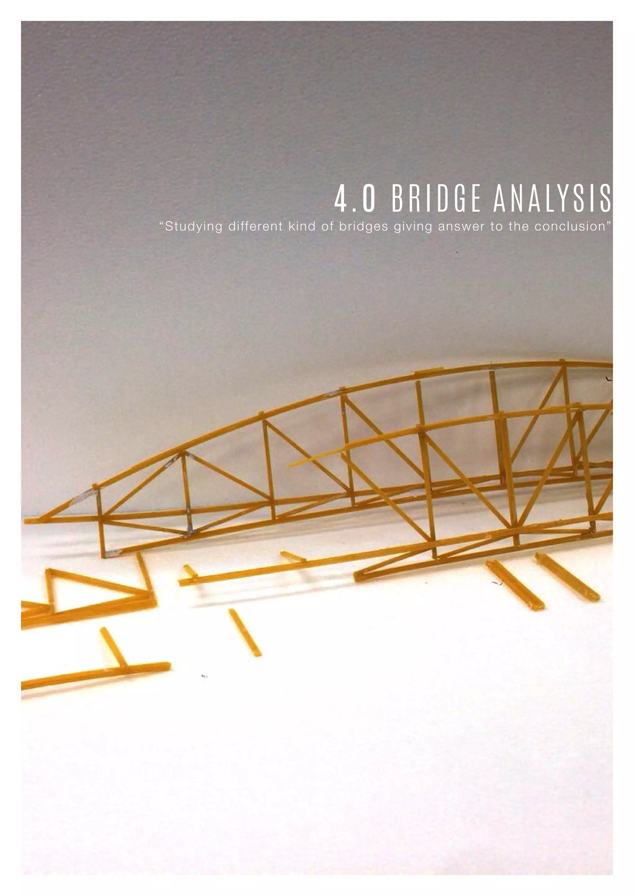
1) The document describes the analysis and testing of different fettuccine bridge designs. Various materials were tested to determine the optimal fettuccine type and adhesive for constructing the bridge model.
2) Seven bridge tests were conducted, with improvements made after each test based on observations of how and where the bridges failed under increasing loads. The fourth and final bridge design achieved the highest efficiency but collapsed prematurely.
3) Material analyses determined that San Remo fettuccine and 3-second glue provided the best strength and bonding for the bridge structure. Various supports were also tested to improve load bearing capacity.
The aim of this manual is to give the design application of the basic requirements of EC8 for new concrete and steel buildings using ETABS. This book can be used by users of ETABS modeler. Is not cover all the steps that you have to carry during designing model using ETABS but is a good manual for those who using Eurocodes.
Post-Tensioned concrete slab was originally developed during the 1930's by a Frenchman, Eugene Freyssinet, who realized that placing concrete under compression greatly increased its strength
Tower design using Dynamic analysis method is now became easier than ever with this simple and effective PDF manual. Starting from modeling, defining till computing results based on Dynamic Analysis you can build the tower of your dream.
Engineering is fun and so does this PDF !
Post-tensioning is simply a method of producing prestressed concrete, masonry, and other structural elements. Post-tensioning is a form of prestressing. Prestressing simply means that the steel is stressed (pulled or tensioned) before the concrete has to support the service loads. Most precast, prestressed concrete is actually pre-tensioned-the steel is pulled before the concrete is poured. Post-tensioned concrete means that the concrete is poured and then the tension is applied-but it is still stressed before the loads are applied so it is still prestressed.
OUTLINE
introduction
classification
loads
materials used
Type of reinforcement
RCC
construction methods in RCC
Analysis and design
Detailing
Basic Rules
Site visit
video
Çok Katlı Yapılarda Düşey DüzensizliklerYusuf Yıldız
Deprem yönetmeliklerinde çok katlı yapılardaki kiriş süreksizlikleri konusunda belirgin bir hüküm yoktur. Bu çalışmada kiriş ve perde süreksizlikleri ayrı ayrı ele alınıp irdelenmiş ve bazı öneriler geliştirilmiştir. Önce, kiriş süreksizlikleri ile ilgili kısıtlı sayıdaki çalışmalar gözden geçirilmiş, daha sonra bir ölçüt geliştirilmiştir. Ölçüt çeşitli pratik örneklere uygulanarak sonuçlar irdelenmiştir. Sonuç
olarak, bu konudaki araştırmaların genişletilmesinin ve deprem yönetmeliğine bir madde eklenmesinin gerekli olduğu vurgulanmıştır. Ayrı bir bölümde alt katlarda kolonlara oturan perdelerin davranışları incelenmiş ve bu konudaki yönetmelik hükümlerinin yeterli kısıtlamalar içerdiği gösterilmiştir.
Book for Beginners, RCC Design by ETABSYousuf Dinar
Advancement of softwares is main cause behind comparatively quick and simple
design while avoiding complexity and time consuming manual procedure. However
mistake or mislead could be happened during designing the structures because of not
knowing the proper procedure depending on the situation. Design book based on
manual or hand design is sometimes time consuming and could not be good aids with
softwares as several steps are shorten during finite element modeling. This book may
work as a general learning hand book which bridges the software and the manual
design properly. The writers of this book used linear static analysis under BNBC and
ACI code to generate a six story residential building which could withstand wind load
of 210 kmph and seismic event of that region. The building is assumed to be designed
in Dhaka, Bangladesh under RAJUK rules to get legality of that concern organization.
For easy and explained understanding the book chapters are oriented in 2 parts. Part A
is concern about modeling and analysis which completed in only one chapter. Part B
is organized with 8 chapters. From chapter 1 to 7 the writers designed the model
building and explained with references how to consider during design so that
creativity of readers could not be threated. Chapter 8 is dedicated for estimation. As a
whole the book will help the readers to experience a building construction related all
facts and how to progress in design. Although the volume I is limited to linear static
analysis, upcoming volume will eventually consider dynamic facts to perform
dynamic analysis. Implemented equations are organized in the appendix section for
easy memorizing.
BNBC and other codes are improving and expending day by day, by covering new
and improved information as civil engineering is a vast field to continue the research.
Before designing something or taking decision judge the contemporary codes and
choose data, equations, factors and coefficient from the updated one.
Book for Beginners series is basic learning book of YDAS outlines. Here only
rectangular grid system modeling and a particular model is shown. Round shape grid
is avoided to keep the study simple. No advanced analysis is described and it is kept
simple for beginners. Only two way slab is elaborated with direct design method,
avoiding other procedures. In case of beam, only flexural and shear designs are made.
T- Beam, L- Beam or other shapes are not shown as rectangular beam was enough for
this study. Bi-axial column and foundation design is not shown. During column and
foundation design only pure axial load is considered. Use of interaction diagram is not
shown in manual design. Load centered isolated and combined footing designs are
shown, avoiding eccentric loading conditions. Pile and pile cap design, Mat
foundation design, strap footing design and sand pile concept are not included in this
Coupling Beams Design in High-Rise Core-Wall Structures
Shear wall structures are most important lateral-force-resisting-systems that have been shown to be
very efficient in resisting seismic loads. But previous earthquake damages showed that the coupling
beams were easily damaged in the earthquake and it was often used as an energy dissipation part in structures.
This document presents an example of analysis design of slab using ETABS. This example examines a simple single story building, which is regular in plan and elevation. It is examining and compares the calculated ultimate moment from CSI ETABS & SAFE with hand calculation. Moment coefficients were used to calculate the ultimate moment. However it is good practice that such hand analysis methods are used to verify the output of more sophisticated methods.
Also, this document contains simple procedure (step-by-step) of how to design solid slab according to Eurocode 2.The process of designing elements will not be revolutionised as a result of using Eurocode 2. Due to time constraints and knowledge, I may not be able to address the whole issues.
While Designing a High rise Load & Structural Analysis is major factor to consider. Here we analyzed some data and try to describe briefly. We hope that it will help you lot :) Done by Neeti Lamic, Bayezid, Sykot Hasan
A Strategic Approach: GenAI in EducationPeter Windle
Artificial Intelligence (AI) technologies such as Generative AI, Image Generators and Large Language Models have had a dramatic impact on teaching, learning and assessment over the past 18 months. The most immediate threat AI posed was to Academic Integrity with Higher Education Institutes (HEIs) focusing their efforts on combating the use of GenAI in assessment. Guidelines were developed for staff and students, policies put in place too. Innovative educators have forged paths in the use of Generative AI for teaching, learning and assessments leading to pockets of transformation springing up across HEIs, often with little or no top-down guidance, support or direction.
This Gasta posits a strategic approach to integrating AI into HEIs to prepare staff, students and the curriculum for an evolving world and workplace. We will highlight the advantages of working with these technologies beyond the realm of teaching, learning and assessment by considering prompt engineering skills, industry impact, curriculum changes, and the need for staff upskilling. In contrast, not engaging strategically with Generative AI poses risks, including falling behind peers, missed opportunities and failing to ensure our graduates remain employable. The rapid evolution of AI technologies necessitates a proactive and strategic approach if we are to remain relevant.
Instructions for Submissions thorugh G- Classroom.pptxJheel Barad
This presentation provides a briefing on how to upload submissions and documents in Google Classroom. It was prepared as part of an orientation for new Sainik School in-service teacher trainees. As a training officer, my goal is to ensure that you are comfortable and proficient with this essential tool for managing assignments and fostering student engagement.
Biological screening of herbal drugs: Introduction and Need for
Phyto-Pharmacological Screening, New Strategies for evaluating
Natural Products, In vitro evaluation techniques for Antioxidants, Antimicrobial and Anticancer drugs. In vivo evaluation techniques
for Anti-inflammatory, Antiulcer, Anticancer, Wound healing, Antidiabetic, Hepatoprotective, Cardio protective, Diuretics and
Antifertility, Toxicity studies as per OECD guidelines
The Roman Empire A Historical Colossus.pdfkaushalkr1407
The Roman Empire, a vast and enduring power, stands as one of history's most remarkable civilizations, leaving an indelible imprint on the world. It emerged from the Roman Republic, transitioning into an imperial powerhouse under the leadership of Augustus Caesar in 27 BCE. This transformation marked the beginning of an era defined by unprecedented territorial expansion, architectural marvels, and profound cultural influence.
The empire's roots lie in the city of Rome, founded, according to legend, by Romulus in 753 BCE. Over centuries, Rome evolved from a small settlement to a formidable republic, characterized by a complex political system with elected officials and checks on power. However, internal strife, class conflicts, and military ambitions paved the way for the end of the Republic. Julius Caesar’s dictatorship and subsequent assassination in 44 BCE created a power vacuum, leading to a civil war. Octavian, later Augustus, emerged victorious, heralding the Roman Empire’s birth.
Under Augustus, the empire experienced the Pax Romana, a 200-year period of relative peace and stability. Augustus reformed the military, established efficient administrative systems, and initiated grand construction projects. The empire's borders expanded, encompassing territories from Britain to Egypt and from Spain to the Euphrates. Roman legions, renowned for their discipline and engineering prowess, secured and maintained these vast territories, building roads, fortifications, and cities that facilitated control and integration.
The Roman Empire’s society was hierarchical, with a rigid class system. At the top were the patricians, wealthy elites who held significant political power. Below them were the plebeians, free citizens with limited political influence, and the vast numbers of slaves who formed the backbone of the economy. The family unit was central, governed by the paterfamilias, the male head who held absolute authority.
Culturally, the Romans were eclectic, absorbing and adapting elements from the civilizations they encountered, particularly the Greeks. Roman art, literature, and philosophy reflected this synthesis, creating a rich cultural tapestry. Latin, the Roman language, became the lingua franca of the Western world, influencing numerous modern languages.
Roman architecture and engineering achievements were monumental. They perfected the arch, vault, and dome, constructing enduring structures like the Colosseum, Pantheon, and aqueducts. These engineering marvels not only showcased Roman ingenuity but also served practical purposes, from public entertainment to water supply.
June 3, 2024 Anti-Semitism Letter Sent to MIT President Kornbluth and MIT Cor...Levi Shapiro
Letter from the Congress of the United States regarding Anti-Semitism sent June 3rd to MIT President Sally Kornbluth, MIT Corp Chair, Mark Gorenberg
Dear Dr. Kornbluth and Mr. Gorenberg,
The US House of Representatives is deeply concerned by ongoing and pervasive acts of antisemitic
harassment and intimidation at the Massachusetts Institute of Technology (MIT). Failing to act decisively to ensure a safe learning environment for all students would be a grave dereliction of your responsibilities as President of MIT and Chair of the MIT Corporation.
This Congress will not stand idly by and allow an environment hostile to Jewish students to persist. The House believes that your institution is in violation of Title VI of the Civil Rights Act, and the inability or
unwillingness to rectify this violation through action requires accountability.
Postsecondary education is a unique opportunity for students to learn and have their ideas and beliefs challenged. However, universities receiving hundreds of millions of federal funds annually have denied
students that opportunity and have been hijacked to become venues for the promotion of terrorism, antisemitic harassment and intimidation, unlawful encampments, and in some cases, assaults and riots.
The House of Representatives will not countenance the use of federal funds to indoctrinate students into hateful, antisemitic, anti-American supporters of terrorism. Investigations into campus antisemitism by the Committee on Education and the Workforce and the Committee on Ways and Means have been expanded into a Congress-wide probe across all relevant jurisdictions to address this national crisis. The undersigned Committees will conduct oversight into the use of federal funds at MIT and its learning environment under authorities granted to each Committee.
• The Committee on Education and the Workforce has been investigating your institution since December 7, 2023. The Committee has broad jurisdiction over postsecondary education, including its compliance with Title VI of the Civil Rights Act, campus safety concerns over disruptions to the learning environment, and the awarding of federal student aid under the Higher Education Act.
• The Committee on Oversight and Accountability is investigating the sources of funding and other support flowing to groups espousing pro-Hamas propaganda and engaged in antisemitic harassment and intimidation of students. The Committee on Oversight and Accountability is the principal oversight committee of the US House of Representatives and has broad authority to investigate “any matter” at “any time” under House Rule X.
• The Committee on Ways and Means has been investigating several universities since November 15, 2023, when the Committee held a hearing entitled From Ivory Towers to Dark Corners: Investigating the Nexus Between Antisemitism, Tax-Exempt Universities, and Terror Financing. The Committee followed the hearing with letters to those institutions on January 10, 202
Read| The latest issue of The Challenger is here! We are thrilled to announce that our school paper has qualified for the NATIONAL SCHOOLS PRESS CONFERENCE (NSPC) 2024. Thank you for your unwavering support and trust. Dive into the stories that made us stand out!
Honest Reviews of Tim Han LMA Course Program.pptxtimhan337
Personal development courses are widely available today, with each one promising life-changing outcomes. Tim Han’s Life Mastery Achievers (LMA) Course has drawn a lot of interest. In addition to offering my frank assessment of Success Insider’s LMA Course, this piece examines the course’s effects via a variety of Tim Han LMA course reviews and Success Insider comments.
Synthetic Fiber Construction in lab .pptxPavel ( NSTU)
Synthetic fiber production is a fascinating and complex field that blends chemistry, engineering, and environmental science. By understanding these aspects, students can gain a comprehensive view of synthetic fiber production, its impact on society and the environment, and the potential for future innovations. Synthetic fibers play a crucial role in modern society, impacting various aspects of daily life, industry, and the environment. ynthetic fibers are integral to modern life, offering a range of benefits from cost-effectiveness and versatility to innovative applications and performance characteristics. While they pose environmental challenges, ongoing research and development aim to create more sustainable and eco-friendly alternatives. Understanding the importance of synthetic fibers helps in appreciating their role in the economy, industry, and daily life, while also emphasizing the need for sustainable practices and innovation.
1. BUILDING STRUCTURE
TREVOR N JC HOREAU 0308914 / TEH KAH KEN 0314502 / LEE MAY WEN, ANDREA 0314320
CHEN ROU ANN 1001G76463 / WONG KWOK KENN 0300146 / NUR ADILA ZAAS 0310417
7. 1.1 OBJECTIVE
The aim of this project is to develop a deeper understanding towards
the tensile and compressive strength of construction materials. Students are
required to design a perfect truss bridge with a high level of aesthetic value
and minimal construction materials. The bridge has to be of a 750mm clear
span, not exceeding the maximum weight of 200g. This report is a compilation
of our undertanding and analysis based on precedent studies conducted, con-
struction materials and the deisgn of our truss bridge.
1.2 INTRODUCTION OF TENSION
Tension describes the pulling force exerted by each end of any one-
dimensional continuous object, be it a string, rope, cable or wire. The tensile
force is focused along the length of an object and pulls uniformly on opposite
ends of it.
1.3 INTRODUCTION OF COMPRESSION
Compressive force (or “compression strength”) refers to the capacity of
a material in resistingpushing forces that are focussed axially. Compressive
force can also be defined as the capacity of a structure to withstand loads
tending to reduce its size.
COMPRESSION TENSION
Image 1
Analysis of
compression (LEFT)
and tension (RIGHT)
IMAGE 1
9. Officially opened in 1890, the Forth Road Bridge occupies a beautiful
location in the Firth of Forth on the East coast of Scotland, connecting Fife
and the North of Scotland with capital city Edinburgh and the South. The
bridge is composed of two railway lines cross the Forth Bridge, supported
47.8 meters above high water, linking much of Northern Scotland with
Edinburgh and England to the South. The lines of track sit on a ‘bridge within
a bridge,’ an internal viaduct supported within the enormous cantilever towers
and arms which is often overlooked.Construction techniques as well as design
improvements can be administered due to ongoing advances in design and
construction, the development of materials and reduction of cost in what is
considered a necessity in a modern day bridge.
2.1 FORTH ROAD BRIDGE
Image 2
Forth Road Bridge
on the east coast of
Scotland
IMAGE 2
10. The bridge spans up to a total of 2460 meters. It is composed of two
approach viaducts, six cantilever arms supported by three towers, with two
central connecting spans. Abutments (supports the lateral pressure of an arch
or span) are found at the end of each of the two outer-most cantilevers. Two
railway lines sit on an internal viaduct supported within the cantilevered
towers; these carried 47.8 meters above high water.
2.2 ELEMENTS OF THE BRIDGE
Four of the six cantilever arms are fixed. These are held strongly in
position by the two granite abutments at the ends of each approach viaduct.
Two ‘suspended spans’, over one hundred and five meters long link the two
outer cantilever towers with the central one. In a nutshell, the superstructure
for this bridge functions as a standard truss – with specific members carrying
out either tension or compressive forces.
The centre of the bridge consists of three main piers, with two cantilever
arms built out from each pier. Two viaducts consisting of a pair of lattice
girders each spanning over fifty-one meters lead up to the centre, which is
ultimately supported over forty meters above high-water level on masonry
piers.
Image 3
Two men represent
main cantilever
tower
11. IN COMPARISON
The two men sat on chairs with outstretched arms represent the main
cantilever towers, in between them is a central span connecting the two.
Anchorage for the cantilevers is provided by the bricks at either side. As load
is applied to the central span (in this case by a third man) the outside men’s
arms come into tension, and the sticks they’re holding and the men’s bodies
experience compressive forces. In reality the bridge has three cantilever
towers, but the principle can be applied equally to this third tower. All
compression members (struts) in this bridge are tubular sections made up of
many small steel plates riveted together, while tension is carried in lattice truss
members. Wind bracing is provided by further lattice trusses spanning
between the main superstructure members.
Image 4
Elevation drawing of
Forth Road Bridge
12. The Francis Scott Bridge, also known as Outer Harbour Bridge or Key
Bridge is a continuous truss bridge spanning over the Patapsco River in
Baltimore, Maryland, The United States of America. This is the longest bridge
(17540 metres) in Baltimore and the third longest span (366 metres) of any
continuous truss in the world. Upon completion, the bridge was officially
opened in March 1977 and estimated to carry 11.5 m`illion vehicles annually.
The technique used in the construction of this bridge can be identified as the
Baltimore truss.
2.3 FRANCIS SCOTT BRIDGE
The Baltimore truss is a subclass of the Pratt truss. It is designed to
prevent buckling in the compression members and also control deflection by
having additional bracing in the lower section of the truss. Due to the rigid and
strong design of this truss, it is mainly used for train bridges.
Image 5
Axono Angle of
Franciss Scott
Bridge
13. The construction of this bridge is complicated in which the order of this
bridge is meticulously calculated. It is achieved by having consistent spacing
of the trusses in the middle section of the bridge together with equal spacing
of the suspended cables in the arch section.
Due to the long span of the arch section of the bridge, a suspended,
continuous truss design is used for this span. The suspended cables linking
between the truss and the deck will prevent the deck from any construction
failures due to tensile and compressive forces when there is presence of load
acting on this section. The trusses on top of the deck are in the form of an
arch because of its stronger structural property than the beam and column
form. In addition, the arch adds for aesthetic value to the design. Apart from
that, the arches will transfer loads back into the bearings on the piers then
into the foundation. Steel sections incorporated between front truss and the
back trusses are to provide stability and torsion resistant to the structure.
Image 6
Front Photo of Scott
Bridge (Top)
Image 7
Elevation of Pratt
Truss (Left Bottom)
Elevation of
Baltimore Truss
(Right Bottom)
14. The bridge’s superstructure involved few construction phases. The first
phase involved building all the span of the bridge across the top of the piers
built in the substructure. A total of eleven piers are constructed in reinforced
concrete prior to provide support to the bridge in which the decks are placed.
Later on, they are further supported and strengthen by the continuous truss.
Image 8
Cables linking the
truss and deck
together.
15. The main steel trusses are prefabricated in four major parts, which
the arch truss would be constructed in two parts, and the regular trusses on
the either side of the arch truss. These separated components made up of
I-beams are then transported to the site by heavy lift floating whereby they are
connected together through welding and girder plates with the aid of crags
on ships to hoist the parts 56.4 metres above the decks (highest point of the
span to the deck under) of the bridge.
Image 9
Construction of the
truss in multiple
parts.
17. 3.1 TYPE OF FETTUCCINE ANALYSIS
As stated in the brief, fettuccine is the only material used for the model.
With this, the tensile and compressive strength of different brands of fettuc-
cine were studied and tested. The most suitable one to be used for our model
was determine.
Methods: -
i. Strips of fettuccine were laid on a flat surface
ii. Load was placed to test the rate of buckling
iii. Time taken until failure was measured in order to determine the strength
& flexibility of the fettuccine
iv. Steps were repeated with a different brand
Results: -
i. San Remo
(chosen fettuccine)
ii. Agnesi
iii. Barilla
- carried most weight
- medium flexibility
- medium rough surface
-carried medium weight
-flexible
-lightweight and thin fetuccini
- carried less weight
-very flexible
-lightest and thinnest fetuccini
Image 10
San Remo
Fettuccine (left)
Image 11
Agnesi Fettuccine
(middle)
Image 12
Barilla
(right)
18. 3.2 ADHESIVE MATERIAL ANALYSIS
Different kinds of glue were tested to determine which was more
efficient in terms of holding the fettucine together. The results obtained from
our analysis is stated below: -
RANKING ADHESIVE MATERIALS REASON
1 3 Seconds Glue i.Highest efficiency
ii. Dries the fastest
iii.Will flow into smallest
corners and joints
2 Elephant Glue i. Moderate Efficiency
ii. Time consumingin terms
of workmanship
iii. Longer solidify time
3 Hot Glue Gun i. Low Efficiency
ii. Long solidify time
iv. Bulky Finishing
v. Drastic increase in weight
when dried
Image 13
3 Seconds Glue
(left)
Image 14
Elephant Glue
(middle)
Image 15
Hot Glue Gun
(right)
19. 3.3 SUPPORT MATERIALS ANALYSIS
Materials that helped us throughout fetuccini bridge’s assignment
ii. Bucket
iii. Hook iv. Water Bottle
i. Weighing Machine
A measuring instrument in determining
the weight or mass of an object. This
was used to measure the weight of
fettuccine pieces to ensure the final
weight of our bridge did not exceed
the maximum limit.
A vertical cylinder with an open top
and a flat bottom, used to carry both
liquids and solids, aiding in the load
distribution process.
Loads used in tests conducted.Serves as a connection between the
fettuccine bridge and the bucket.
Image 16
Weighing
Machine
(Top Left)
Image 17
Blue Bucket
(Top Right)
Image 18
Steel Hook
(Bottom Left)
Image 19
Water Bottle
(Bottom Right)
20. 3.3 STRENGTH OF MATERIAL ANALYSIS
As fettuccini is the only material used for the model, its quality and
strength is required to be studied and thoroughly tested before making the
model. We aim to:
i) Achieve a high level of aesthetic value
ii) Use minimal construction material to achieve high efficiency.
2. The table (Table 1) below shows the strength of each fettuccine analysed
by applying point pressure on the middle. Different numbers, orientation and
arrangements of fettuccine were used to form the members.
Clear Span
(cm)
Length Of Fettuccine
(cm)
Perpendicular
Distance
Weight Sustained
(Horizontal Facing)
Weight Sustained
(Horizontal Facing)
20
20
20
20
20
26
26
26
26
26
1
2
3
4
5
2
3
4
5
6.8
2.7
3.7
4.8
5.8
6
TABLE 1 Strength of each fettuccine analysed by applying point pressure on the middle
IMAGE 20 The loads (and reactions) bend the fettuccine and try to shear through it.
3. The strength of one fettucine appears to be lower when faced horizontally than
when it is faced vertically from 1 stick to 4 sticks. However, after 5 sticks, results turned
out to be the opposite. In conclusion, the greater the area exposed relative to its volume,
the weaker the fettuccine member is in resisting strains and stresses (The easier it is for
the member to break apart)
21. DIRECTION OF FORCES DIRECTION OF FORCES
4. From the result, we decided to use fettuccine members of 1 to 4 sticks with vertical
facing on the truss member that required less strength.
IMAGE 21 When the fettuccine is loaded by forces, stress and strains are created throughout the interior of the beam.
TESTING ON SINGLE MEMBER
Strength: Very strong
This design is most preferable in terms of efficiency and
workmanship
Strength: Not so strong
This is an effective design with minimal human error
IMAGE 22 I-Beam
IMAGE 23 Layerrings
23. Completed fettuccine models were put to a test. The main aim of this test is to allow
the bridge to withstand the greatest load but a minimum load was set initially. This is used to
identify the model with the greatest potential to be constructed for the final bridge. The
series of test shows the ups and downs on the bridges constructed. Through each test,
considerations were made and adapted in the new bridge and consecutively. A total of
seven tests were conducted prior to making the final bridge.
4.1 MISSION
24. 4.1.1 BRIDGE TESTING ONE
Details of the Bridge:
Height and width = 750mm (width)
Length (top chord) = 600mm
Length (bottom chord) = 750mm
Weight of this bridge = 125g
Maximum load = 2350g
Efficiency = (2.350kg)^2 / 0.125kg = 44.18
ANALYSIS
The bridge did not bend or twist as weight is gradually added.
Nevertheless, only the hook support broke when load reached at 2350g.
The bridge holds it form and position.
CONSIDERATION: -
improve on the hook support
25. BRIDGE TEST
ONE
IMAGE 24 IMAGE 25
IMAGE 26 IMAGE 27
IMAGE 28
Image 24
First Part
Image 25
Second Part
Image 26
Third Part
Image 27
Fourth Part
Image 28
Fifth Part
26. 4.1.2 BRIDGE TESTING TWO
Details of the Bridge:
Height and width = 750mm (width)
Length (top chord) = 600mm
Length (bottom chord) = 750mm
Weight of this bridge = 125g
Maximum load = 2430 g
Efficiency = (2.430kg)^2 / 0.125kg = 47.24
ANALYSIS
After the failure of the previous hook support, we improvised and came up
with a different hook support design. A cross-bracing support was added.
This support is able to withstand up to 2.4kg until the hook support broke.
The failure of this bridge is only at the hook support. Meanwhile, the bridge
retained its form and did not collapse.
CONSIDERATION: -
improve on the hook support
27. IMAGE 29 IMAGE 30
IMAGE 31 IMAGE 32
BRIDGE TEST
TWO
Image 29
First Part
Image 30
Second Part
Image 31
Third Part
Image 32
Fourth Part
28. 4.1.3 BRIDGE TESTING THREE
Details of the Bridge:
Height and width = 750mm (width)
Length (top chord) = 600mm
Length (bottom chord) = 750mm
Weight of this bridge = 130g
Maximum load = 8100g
Efficiency = (8.100kg)^2 / 0.130kg = 504.69
ANALYSIS
The hook support was rectified and an I-beam replaces the
horizontal support. The bridge remains stable has load is gradually added.
The hook support did not break this time but however, the bottom
chord snapped causing the whole bridge to collapse.
CONSIDERATION: -
Add support on the top & bottom chord
29. IMAGE 33 IMAGE 34
IMAGE 35 IMAGE 36
BRIDGE TEST
THREE
IMAGE 37
Image 33
First Part
Image 34
Second Part
Image 35
Third Part
Image 36
Fourth Part
Image 37
Fifth Part
30. 4.1.4 BRIDGE TESTING FOUR
Details of the Bridge:
Height and width = 750mm (width)
Length (top chord) = 600mm
Length (bottom chord) = 750mm
Weight of this bridge = 130g
Maximum load = 700 g
Efficiency = (0.700kg)^2 / 0.130kg = 3.77
ANALYSIS
This bridge was an exact replicate of the previous bridge but blown
up to a bigger scale to fit the requirements of a 750mm clear span. All
members remain the same thickness and also the use of I beams as the hook
support.The failure of this bridge was identified as workmanship effort. The
bridge twisted as load is gradually added up to the point the sides
broke causing the whole bridge to collapse. This is due to the bottom
chord not being straight when constructing.
CONSIDERATION: -
- Improve workmanship
- Ensure bottom chord is straight and sits balanced
on the table.
31. IMAGE 38 IMAGE 39
IMAGE 40 IMAGE 41
BRIDGE TEST
FOUR
IMAGE 42
Image 38
First Part
Image 39
Second Part
Image 40
Third Part
Image 41
Fourth Part
Image 42
Fifth Part
32. 4.1.5 BRIDGE TESTING FIVE
Details of the Bridge:
Height and width = 85mm (width)
Length (top chord) = 843mm
Length (bottom chord) = 850mm
Weight of this bridge = 130g
Maximum load = 2700g
Efficiency = (2.700kg)^2 / 0.130kg = 56.08
ANALYSIS
All members remain the same thickness and use of I beams as the
hook support. This bridge failed as the bottom chord snapped.
However, the hook support did not break and retain its form.
CONSIDERATION: -
Strengthen the bottom chord
33. IMAGE 43 IMAGE 44
IMAGE 45 IMAGE 46
BRIDGE TEST
FIVE
IMAGE 47
Image 43
First Part
Image 44
Second Part
Image 45
Third Part
Image 46
Fourth Part
Image 47
Fifth Part
34. 4.1.6 BRIDGE TESTING SIX
Details of the Bridge:
Height and width = 110mm from highest point to bottom (height)
775 (width)
Length (top chord) = 881mm
Length (bottom chord) = 850mm
Weight of this bridge = 273g
Maximum load = 2825 units
Efficiency = (2.825kg)^2 / 0.273kg = 29.23
ANALYSIS
After doing the precedent studies, we decided to try out another bridge
with a different design. This bridge is steady and strong. However, the failure of
this bridge happens on the hook support which is a cross-braced design. Upon
adding load up to 2.8kg, the hook support snaps. However the members of
bridge remained intact. The bridge remained its form.
CONSIDERATION: -
Straigthen its hook support.
35. IMAGE 48 IMAGE 49
IMAGE 50 IMAGE 51
BRIDGE TEST
SIX
IMAGE 52
Image 48
First Part
Image 49
Second Part
Image 50
Third Part
Image 51
Fourth Part
Image 52
Fifth Part
36. 4.1.7 BRIDGE TESTING SEVEN
Details of the Bridge:
Height and width = 110mm from highest point to bottom (height) 775 (width)
Length (top chord) = 881mm
Length (bottom chord) = 850mm
Weight of this bridge = 280g
Maximum load = 5315g
Efficiency = (5.315kg)^2 / 0.280kg = 100.89
ANALYSIS
The bridge has same design as the previous bridge. However, the only
difference is the hook support. The conclusion was drawn based on the
previous tests that a hook support made from multiple layers of fetuccini
is not as strong as a hook support composed of I beams. In this test,
the bridge withstand up to 5.3kg and “crack” sound can be heard.
The failure of this bridge happens when one of the chord could not
take the load causing the whole bridge to collapse. However,
the hook support did not deform.
CONSIDERATION: -
Strengthen the supports on the side as it fails to hold
up the bridge.
37. IMAGE 53 IMAGE 54
IMAGE 55 IMAGE 56
BRIDGE TEST
SEVEN
IMAGE 57
Image 53
First Part
Image 54
Second Part
Image 55
Third Part
Image 56
Fourth Part
Image 57
Fifth Part
39. 5.1 FINAL DESIGN OF OUR FETTUCCINE BRIDGE
Details of the Bridge:
Height and width = 83mm(height)
52mm (width)
Length (top chord) = 753mm
Length (bottom chord) = 866.75mm
Weight of this bridge = 203g
Maximum load = 3.2kg
ANALYSIS
Efficiency = (max load)2/ Weight of bridge = 10.24/0.203 = 50.44% efficient.
Although many considerations were taken into the final bridge design, the total
weight of the bridge once completed was heavier than previous models, and we
feared a lower efficiency than 50%. However, during testing, we realised the final
bridge design was a rigid and strong one and could have taken more load if
workmanship had been precise and accurate, unfortunately, with fettuccini sticks
we cannot guarantee that. It was one part of the bottom chord that snapped away
and we strongly believe it was due to the inconsistency in the overlapping
method of fettuccini pieces making up the chords.
CONSIDERATION
If we were to carry out a second final test, we would shorten the total length of the chord
to reduce some weight and add rigidity. We would also remove all the top (single layer)
and bottom (double layer) horizontal connecting members and replace them with a single
layer x-cross bracing from one façade to another. We believe this would drop down the
weight of our bridge by at least 30-40g, and the max load would probably be a little bit
less, but our goal is obtaining best efficiency, therefore we would expect a higher
efficiency value than 50%.
40. IMAGE 58 IMAGE 59
IMAGE 60 IMAGE 61
FINAL
BRIDGE TEST
IMAGE 62
Image 58
First Part
Image 59
Second Part
Image 60
Third Part
Image 61
Fourth Part
Image 62
Fifth Part
44. AIM
We need to identify 6 Case Study from the activity that our lecturers provided to help on
our understanding about truss analysis. As every case has the same load applied on it, we found out that
the Fx Fy and Momentum towards every cases has the same calculation also.
The calculations: -
∑Fx = 0
20 + 5- + 80 + Ra + RJx = 0
∑Fx = 0
150 + Rx+RJx= 0
-100+15-60-50-RJy= 0
(-RJyx 3.5) – 50(3.5) -80 (3.5) +60(6) -152(2) -20(1) + 50(8) + 100(2) = 0
RJx (3.5) = 185
RJx=52.857
150+ Ra +52.587 = 0
Ra=-202.827
To determine wether its a perfect truss: -
2J = m+3
1. 2J = 2 (a)
= 18
2. m + 3 = 15 + 3
= 18
thus,
It is a perfect truss.
77. COMPRESSION AND TENSION ANALYSIS
Analyzing all the cases in general, it is visible which is the most efficient amongst the 6.
Firstly, let us imagine all these cases are acting out simultaneously. Secondly, an important
point to note is that the more force there is on an individual member, the more stress it is
undertaking, hence that member will break more easily.
For example, looking at case 2, the vertical column takes the most force of 210KN and will
fail first. And in this case, is the least efficient.
In case 3, the vertical column that transfers 150KN would collapse followed by the top
member that transfers 202.86KN as the force is not distributed evenly to the nearby
members.
Case 4 and 5 have two end vertical members transferring zero load, hence making those
members inactive and useless in this system. However case 4 would collapse before case 5
because the second column from the left holds more weight than the 5th case, making case
5 truss system more efficient than case 4 due to the weight distribution.
In case 6, the two top horizontal members will collapse first as they are transferring the most
load. Case 6 is of moderate efficiency compared to case 4 and 5. However, case 1 is the
most efficient as there is an obvious better distribution of load.
78. Analyzing all the cases in general, it is visible which is the most efficient amongst the 6.
Firstly, let us imagine all these cases are acting out simultaneously. Secondly, an important
point to note is that the more force there is on an individual member, the more stress it is
undertaking, hence that member will break more easily.
For example, looking at case 2, the vertical column takes the most force of 210KN and will
fail first. And in this case, is the least efficient.
In case 3, the vertical column that transfers 150KN would collapse followed by the top
member that transfers 202.86KN as the force is not distributed evenly to the nearby
members.
Case 4 and 5 have two end vertical members transferring zero load, hence making those
members inactive and useless in this system. However case 4 would collapse before case 5
because the second column from the left holds more weight than the 5th case, making case
5 truss system more efficient than case 4 due to the weight distribution.
In case 6, the two top horizontal members will collapse first as they are transferring the most
load. Case 6 is of moderate efficiency compared to case 4 and 5. However, case 1 is the
most efficient as there is an obvious better distribution of load.
CONCLUSION
80. IMAGE REFERENCES
Image 1 : retrieved from http://santabarbarastrength.com/wp-content/uploads/2014/01/400px-
compression_tension_and_shear_forces-300x151.png
Image 2 : retrieved from http://i2.wp.com/caledonianmercury.com/wp-content/uploads/2013/05/Forth-
Bridge-2.jpg?resize=1502%2C738
Image 3 : retrieved from http://www.engineering-timelines.com/why/forthRailBridge/forthRailBridge_03.jpg
Image 4 : retrieved from http://dita2indesign.sourceforge.net/dita_gutenberg_samples/dita_
encyclopaedia_britannica/html/entries/images/bridges_23.png
Image 5 : retrieved from http://www.ce.jhu.edu/baltimorestructures/Buildings/Francis%20Scott%20
Key%20 Bridge/2.JPG
Image 6 : retrieved from http://skyserver.sdss3.org/sdss2013/images/keybridge.jpg
Image 7 : retrieved from https://www.cs.princeton.edu/courses/archive/fall09/cos323/assign/truss/ps2/truss2.png
Image 8 : retrieved from http://static.panoramio.com/photos/large/8221330.jpg
Image 9 : retrieved from http://betterarchitecture.files.wordpress.com/2014/01/sydney-harbour-bridge-under-con-
struction.jpg
Image 10 : retrieved from https://grocermart.com/image/cache/data/SanRemo1/fettuccine-1800x1800.jpg
Image 11 : retrieved from http://en.creation.com.tw/userfiles/sm/sm350_images_E1/73/2012011963065545.jpg
Image 12 : retrieved from http://ecx.images-amazon.com/images/I/81MRq%2BcQYdL._SL1500_.jpg
Image 13 : retrieved from http://vitaltechnical.com/image/cache/data/product/super/VT-802-1qxt-500x500.jpg
Image 14 : retrieved from http://www.buystationery.com.sg/upload/1262941565.jpg
Image 15 : retrieved from http://letsmakerobots.com/files/field_primary_image/24076.jpg?
Image 16 : retrieved from http://media1.in.88db.com/in/DB88UploadFiles/2012/11/21/17750650-294E-4435-AC42-
8154EE2496E9.jpg
Image 17 : retrieved from http://www.axis-cleaningsupplies.co.uk/media/catalog/product/cache/1/image/9df78e-
ab33525d08d6e5fb8d27136e95/u/h/uhbb1030l_10ltr_bucket_blue.png
Image 18 : retrieved from http://www.preserveshop.co.uk/images/stainless-steel-hanging-hook.jpg
Image 19 : retrieved from http://cdn5.triplepundit.com/wp-content/uploads/2009/11/bottled-water.jpg
Image 20 : drawn by Chen Rou Anne
Image 21: drawn by Chen Rou Anne
Image 22 : drawn by Chen Rou Anne
Image 23 : drawn by Chen Rou Anne
Image 24 : photograph by Kenn Wong
Image 25: photograph by Kenn Wong
Image 26 : photograph by Kenn Wong
81. Image 27 : photograph by Kenn Wong
Image 28 : photograph by Kenn Wong
Image 29 : photograph by Andrea Lee
Image 30 : photograph by Andrea Lee
Image 31 : photograph by Andrea Lee
Image 32 : photograph by Andrea Lee
Image 33 : photograph by Andrea Lee
Image 34 : photograph by Andrea Lee
Image 35 : photograph by Andrea Lee
Image 36 : photograph by Andrea Lee
Image 37 : photograph by Adila Zaas
Image 38 : photograph by Adila Zaas
Image 39 : photograph by Adila Zaas
Image 40 : photograph by Adila Zaas
Image 41 : photograph by Adila Zaas
Image 42 : photograph by Adila Zaas
Image 43 : photograph by Kenny Teh
Image 44 : photograph by Kenny Teh
Image 45 : photograph by Kenny Teh
Image 46 : photograph by Kenny Teh
Image 47 : photograph by Adila Zaas
Image 48 : photograph by Adila Zaas
Image 49 : photograph by Adila Zaas
Image 50 : photograph by Adila Zaas
Image 51 : photograph by Adila Zaas
Image 52 : photograph by Kenny Teh
Image 53 : photograph by Kenny Teh
Image 54 : photograph by Kenny Teh
Image 55 : photograph by Kenny Teh
Image 57 : photograph by Kenny Teh
82. Image 58 : photograph by Kenny Teh
Image 59 : photograph by Kenny Teh
Image 60 : photograph by Kenny Teh
Image 61 : photograph by Kenny Teh
Image 62 : photograph by Kenny Teh
Image 63 : photograph by Kenny Teh
Image 64 : photograph by Kenny Teh
Image 65 : photograph by Kenny Teh
Image 66 : photograph by Kenny Teh
Image 67 : photograph by Kenny Teh
83. REFERENCE LISTS
Kozel, S. (1997, August 14). Francis Scott Key Bridge (Outer Harbor Crossing). Retrieved October 8, 2014,
from http://www.roadstothefuture.com/Balt_Outer_Harbor.html
Overview of Forth Bridge. (2014, January 1). Retrieved October 8, 2014, from http://www.scottish-places.info/
features/featurefirst1053.html
Sangree, R. (2014). An Engineer’s Guide to Baltimore. Retrieved October 8, 2014, from
http://www.ce.jhu.edu/baltimorestructures/Index.php?location=Francis%20Scott%20Key%20Bridge
T H Kwok, D. (2009, April 1). ANALYSIS OF FRANCIS SCOTT KEY BRIDGE (BALTIMORE). Retrieved October
8, 2014, from http://www.bath.ac.uk/ace/uploads/StudentProjects/Bridgeconference2009/Papers/KWOK.pdf
Triangulation & measurements at the Forth bridge; reprinted, with additions, from “The Engineer.” (1887,
January 1). Retrieved October 8, 2014, from http://www.worldcat.org/title/triangulation-measurements-at-the-
forth-bridge-a-description-of-the-measurements-of-a-base-line-the-triangulation-of-stations-therefrom-and-
the-setting-out-of-the-foundations-and-portions-of-the-steel-work-reprinted-with-additions-from-the-engi-
neer/oclc/123250114