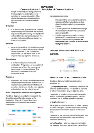
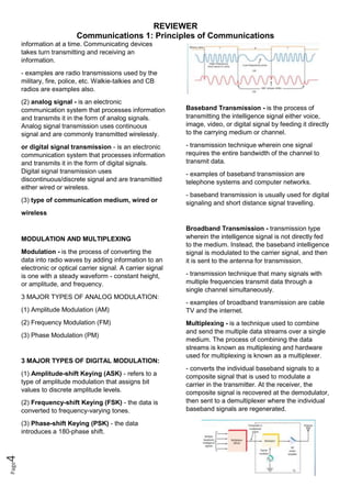
REVIEWER
Communications 1: Principles of Communications
Page
1
INTRODUCTION TO COMMUNICATION SYSTEM
The communication system is a system
which describes the information exchange
between two points. The process of transmission
and reception of information is called
communication. The major elements of
communication are the Transmitter of
information, Channel or medium of
communication and the Receiver of
information.
Types Of Communication Systems
Depending on Signal specification or technology,
the communication system is classified as follows:
(1) Analog
Analog technology communicates data as
electronic signals of varying frequency or
amplitude. Broadcast and telephone transmission
are common examples of Analog technology.
(2) Digital
In digital technology, the data are generated and
processed in two states: High (represented as 1)
and Low (represented as 0). Digital technology
stores and transmits data in the form of 1s and
0s.
Depending on the communication channel, the
communication system is categorized as follows:
1. Wired (Line communication) - refers to the
transmission of data over a wire-based
communication technology. Wired communication
is also known as wireline communication.
• Parallel wire communication
• Twisted wire communication
• Coaxial cable communication
• Optical fiber communication
2. Wireless (Space communication) - is a broad
term that incorporates all procedures and forms of
connecting and communicating between two or
more devices using a wireless signal through
wireless communication technologies and
devices.
• Ground wave communication
• Skywave communication
• Space wave communication
• Satellite communication
Examples Of Communication Systems
The following are a few examples of
communication systems:
1. Internet
2. Public Switched Telephone network
3. Intranet and Extranet
4. Television
Elements Of Communication Systems
The definitions of the terms used in the
communication system are discussed below.
Information
 Message or information is the entity that is
to be transmitted. It can be in the form of
audio, video, temperature, picture,
pressure, etc.
Signal
 The single-valued function of time that
carries the information. The information is
converted into an electrical form for
transmission.
Transducer
 A device or an arrangement that converts
one form of energy to the other. An
electrical transducer converts physical
variables such as pressure, force,
temperature into corresponding electrical
signal variations. Example: Microphone –
converts audio signals into electrical
signals. Photodetector – converts light
signals into electrical signals.
Amplifier
 The electronic circuit or device that
increases the amplitude or the strength of
the transmitted signal is called an
amplifier. When the signal strength
REVIEWER
Communications 1: Principles of Communications
Page
2
becomes less than the required value,
amplification can be done anywhere in
between transmitter and receiver. A DC
power source will provide for the
amplification.
Modulator
 As the original message signal cannot be
transmitted over a large distance because
of their low frequency and amplitude, they
are superimposed with high frequency
and amplitude wave called carrier wave.
This phenomenon of superimposing of
message signal with a carrier wave is
called modulation. And the resultant wave
is a modulated wave which is to be
transmitted.
Again, there are different types of Modulation.
i. Amplitude Modulation (AM)
The process of changing the amplitude of the
signal wave by impressing or superimposing it on
a high-frequency carrier wave, keeping its
frequency constant is called amplitude
modulation.
ii. Frequency Modulation (FM)
Frequency modulation is a technique in which the
frequency of the message signal is varied by
modulating with a carrier wave. It is better than
amplitude modulation because it eliminates noise
from various sources.
iii. Phase Modulation (PM)
The phase of the carrier wave changes the phase
of the signal wave. The phase shift after
modulation is dependent on the frequency of the
carrier wave as well. Phase modulated waves are
immune to noise to a greater extent.
Transmitter
 It is the arrangement that processes the
message signal into a suitable form for
transmission and subsequently reception.
Antenna
 An Antenna is a structure or a device that
will radiate and receive electromagnetic
waves. So, they are used in both
transmitters and receivers. An antenna is
basically a metallic object, often a
collection of wires. The electromagnetic
waves are polarized according to the
position of the antenna.
Channel
 A channel refers to a physical medium
such as wire, cables, space through which
the signal is passed from the transmitter to
the receiver. There are many channel
impairments that affect channel
performance to a pronounced level. Noise,
Attenuation, and distortion to mention the
major impairments.
Noise
 Noise is one of the channel imperfection
or impairment in the received signal at the
destination. There are external and
internal sources that cause noise. External
sources include interference, i.e.,
interference from nearby transmitted
signals (cross talk), interference generated
by a natural source such as lightning,
solar or cosmic radiation, automobile
generated radiation, etc. The external
noise can be minimized and eliminated by
the appropriate design of the channel,
shielding of cables. Also, by digital
transmission external noise can be much
minimized.
 Internal sources include noise due to
random motion and collision of electrons
in the conductors, thermal noise due to
diffusion and recombination of charge
carriers in other electronic devices.
Internal noise can be minimised by cooling
and using digital technology for
transmission.
• A different cable designs.
• Proper design of the channel.
• Use digital transmission
• Using BPF or LPF at the receiver side.
Attenuation
 Attenuation is a problem caused by the
medium. When the signal is propagating
for a longer distance through a medium,
depending on the length of the medium
the initial power decreases. The loss in
initial power is directly proportional to the
REVIEWER
Communications 1: Principles of Communications
Page
3
length of the medium. Using amplifiers,
the signal power is strengthened or
amplified to reduce attenuation. Also,
digital signals are comparatively less
prone to attenuation than analogue
signals.
Distortion
 It is also another type of channel problem.
When the signal is distorted, the distorted
signal may have frequency and bandwidth
different from the transmitted signal. The
variation in the signal frequency can be
linear or non-linear.
Receiver
 An arrangement that extracts the message
or information from the transmitted signal
at the output end of the channel and
reproduces it in a suitable form as the
original message signal is a receiver.
Demodulator
 It is the inverse phenomenon of
modulation. The process of separation of
message signal from the carrier wave
takes place in the demodulator. The
information is retrieved from the
modulated wave.
Repeaters
 Repeaters are placed at different locations
in between the transmitter and receiver. A
repeater receives the transmitted signal,
amplifies it and send it to the next repeater
without distorting the original signal.
Block Diagram of Communication Systems
The block diagram given below represents the
flow of the signal from the source to the
destination. The role of every device and
arrangement discussed above is better
understood.
THE COMMUNICATION SYSTEM
 the system that allows transmission and
reception of information between two
distant points is called communication
system.
 it is the system that makes the exchange
of information between the source and
receiver possible.
 the electronic communication system
consists of 3 major elements to make
distant communication possible, the
transmitter, the channel or medium and
lastly the receiver.
GENERAL MODEL OF COMMUNICATION
SYSTEMS:
See Introduction for definition
TYPES OF ELECTRONIC COMMUNICATION
Electronic Communications are classified
according to:
(1) simplex (one way) - commonly known as the
one-way communication. The system is capable
of either transmission only or receiving only.
- examples of simplex communication are radio
and TV broadcasting (receiving only), remote
controlled car or drones (transmission only).
or duplex (two way –
full duplex - communication on its fullest capacity
is called full-duplex, wherein two communicating
devices can transmit and receive at the same
time.
- example is two persons communicatingwith one
another over the telephone, theycan talk and
listen simultaneously.
or half-duplex) - also two-way communication
but only one device on one end can transmit the
REVIEWER
Communications 1: Principles of Communications
Page
4
information at a time. Communicating devices
takes turn transmitting and receiving an
information.
- examples are radio transmissions used by the
military, fire, police, etc. Walkie-talkies and CB
radios are examples also.
(2) analog signal - is an electronic
communication system that processes information
and transmits it in the form of analog signals.
Analog signal transmission uses continuous
signal and are commonly transmitted wirelessly.
or digital signal transmission - is an electronic
communication system that processes information
and transmits it in the form of digital signals.
Digital signal transmission uses
discontinuous/discrete signal and are transmitted
either wired or wireless.
(3) type of communication medium, wired or
wireless
MODULATION AND MULTIPLEXING
Modulation - is the process of converting the
data into radio waves by adding information to an
electronic or optical carrier signal. A carrier signal
is one with a steady waveform - constant height,
or amplitude, and frequency.
3 MAJOR TYPES OF ANALOG MODULATION:
(1) Amplitude Modulation (AM)
(2) Frequency Modulation (FM)
(3) Phase Modulation (PM)
3 MAJOR TYPES OF DIGITAL MODULATION:
(1) Amplitude-shift Keying (ASK) - refers to a
type of amplitude modulation that assigns bit
values to discrete amplitude levels.
(2) Frequency-shift Keying (FSK) - the data is
converted to frequency-varying tones.
(3) Phase-shift Keying (PSK) - the data
introduces a 180-phase shift.
Baseband Transmission - is the process of
transmitting the intelligence signal either voice,
image, video, or digital signal by feeding it directly
to the carrying medium or channel.
- transmission technique wherein one signal
requires the entire bandwidth of the channel to
transmit data.
- examples of baseband transmission are
telephone systems and computer networks.
- baseband transmission is usually used for digital
signaling and short distance signal travelling.
Broadband Transmission - transmission type
wherein the intelligence signal is not directly fed
to the medium. Instead, the baseband intelligence
signal is modulated to the carrier signal, and then
it is sent to the antenna for transmission.
- transmission technique that many signals with
multiple frequencies transmit data through a
single channel simultaneously.
- examples of broadband transmission are cable
TV and the internet.
Multiplexing - is a technique used to combine
and send the multiple data streams over a single
medium. The process of combining the data
streams is known as multiplexing and hardware
used for multiplexing is known as a multiplexer.
- converts the individual baseband signals to a
composite signal that is used to modulate a
carrier in the transmitter. At the receiver, the
composite signal is recovered at the demodulator,
then sent to a demultiplexer where the individual
baseband signals are regenerated.
REVIEWER
Communications 1: Principles of Communications
Page
5
3 BASIC TYPES OF MULTIPLEXING:
(1) Frequency-division Multiplexing – the
intelligence signals modulate subcarriers on
different frequencies that are then added
together, and the composite signal is used to
modulate the carrier.
(2) Time-division Multiplexing - the multiple
intelligence signals are sequentially sampled, and
a small piece of each is used to modulate the
carrier.
(3) Code-division Multiplexing - the signals to
be transmitted are converted to digital data that is
then uniquely coded with a faster binary code.
The signals modulate a carrier on the same
frequency.
The ElectromagneticWaves
Electromagnetic Waves – are invisible forms of
energy that travel though the universe. However,
you can see some of the results of this energy.
The light that our eyes can see is part of the
electromagnetic spectrum. In physics,
electromagnetic radiation consists of waves of the
electromagnetic field, which propagate through
space and carry momentum and electromagnetic
radiant energy. It includes radio waves,
microwaves, infrared, light, ultraviolet, X-rays,
and gamma rays.
Frequency and Wavelength
The frequency and wavelengths are the two
important properties of electromagnetic waves.
Each application or communications technology is
allocated with certain frequency and operate with
a certain wavelength.
Frequency (𝒇) - is the number of times a
particular phenomenon occurs in a given period
of time. In electronics, frequency is the number of
cycles of a repetitive wave that occurs in a given
time period.
- the unit of frequency is Hertz.
Wavelength (λ) - is the distance occupied by one
cycle of a wave, and it is usually expressed in
meters.
Speed of light (c) - the speed of electromagnetic
waves in free space is the speed of light which is
equal to 300,000,000 m/sec or 3 x 10⁸ m/sec.
Frequency, wavelength, and velocity relationship:
𝝀𝒇 = 𝒄
THE ELECTROMAGNETIC SPECTRUM
- Is comprised of all frequencies of
electromagnetic radiation that propagate energy
and travel through space in the form of waves.
- Longer wavelengths with lower frequencies
make up the radio spectrum. Shorter
wavelengths with higher frequencies make up the
optical spectrum. The portion of the spectrum
that humans can see is called the visible
spectrum.
- Is generally regarded as a natural resource of
the nation where it is used. Spectrum has often
been referred to as the "fuel" for wireless
technology and the "oxygen" of the Internet. It is
managed and allocated to avoid harmful
interference with other users of the spectrum.
REVIEWER
Communications 1: Principles of Communications
Page
6
ALLOCATION OF THE ELECTROMAGNETIC
SPECTRUM
The electromagnetic spectrum is sub-divided for
allocation to different communication applications.
Bandwidth (BW) is that portion of the
electromagnetic spectrum occupied by a signal. It
is also the frequency range over which a receiver
or other communication electronic circuit
operates. Each bandwidth is called according to
the range of frequency where it operates or
according to its wavelength. Listed below are the
classifications of the EM spectrum:
(1) Extremely Low Frequencies (ELF)
- (30 Hz – 300 Hz) signals which radiates in this
spectrum are called radio waves. Power line
frequencies (50 and 60 Hz) are within this range,
also those frequencies in the low end of the
human audio range.
(2) Ultra Low Frequencies (ULF)
- (300 Hz - 3 KHz) this is the normal range of
human speech. Also referred to as the voice
frequency.
(3) Very Low Frequencies (VLF)
- (9 KHz – 30 KHz) this include the higher end of
the human hearing range up to about 15 or 20
KHz. Many musical instruments make sounds in
this range as well as in the ELF and VF ranges.
The VLF range is also used in some government
and military communication.
(4) Low Frequencies (LF)
- (30 KHz – 300 KHz) the primary communication
services using this range are in aeronautical and
marine navigation. Frequencies in this range are
also used as subcarriers, signals that are
modulated by the baseband information. This
band is also known as kilometer band or
kilometer wave.
(5) Medium Frequencies (MF)
- (300 KHz – 3000 KHz) also known as
hectometer band. The major application of
frequencies in this range is AM radio
broadcasting (535 to 1605 kHz). Other
applications in this range are various marine and
amateur radio communication.
(6) High Frequencies (HF)
- (3 MHz – 30 MHz) also known as short waves.
All kinds of simplex broadcasting and half duplex
two-way radio communication take place in this
range (amateur radio and CB communication).
Government and military services use these
frequencies for two-way communication.
(7) Very High Frequencies (VHF)
- (30 MHz – 300 MHz) the most popular band of
the spectrum. Widely employed for television,
FM radio broadcasting (88 to 108 MHz) and
mobile radio communications.
(8) Ultra High Frequencies (UHF)
- (300 MHz - 3000 MHz) also known as the
decimeter band. This band includes UHF TV
channels, land mobile communication and
services such as cellular telephones as well as for
military communication. (Radar and navigation
services).
(9) Super High Frequencies (SHF)
- (3 GHz – 30 GHz) this frequency range is called
microwaves. These microwave frequencies are
widely used for satellite communication and
radar. Wireless local-area networks (LANs) and
many cellular telephone systems also occupy this
region.
(10) Extremely High Frequencies (EHF)
- (30 GHz – 300 GHz) Electromagnetic signals
with frequencies higher than 30 GHz are referred
to as millimeter waves. This band is used for
satellite communication telephony, computer
data, short-haul cellular networks, and some
specialized radar.
(11) Optical Spectrum
- the spectrum which is occupied by the light
waves. There are three different types of light
waves: infrared, visible, and ultraviolet.
1. Infrared - infrared wavelengths are in the
range 0.1 millimeter to 0.7 micrometer.
Infrared is produced by light-bulbs, our
bodies, and any physical equipment that
generates heat. Infrared signals can also
be generated by special types of light-
emitting diodes (LEDs) and lasers. Fiber
optic communication also uses infrared
waves.
REVIEWER
Communications 1: Principles of Communications
Page
7
2. Visible Spectrum - above the infrared
waves is the visible spectrum or light.
Light ranges from 400 – 800 nanometer.
Light waves can be modulated and
transmitted through glass fibers. Because
of its very high frequency it has the ability
to handle a tremendous amount of
information. Light can also travel through
free space, it can be modulated by voice,
video, and data information and be
transmitted.
3. Ultraviolet - UV light waves have
wavelength ranging from 4 to 400
nanometer. It is also generated by
mercury vapor lights and some other types
of lights such as fluorescent lamps and
sun lamps. Ultraviolet is not used for
communication; its primary use is medical.
BANDWIDTH CALCULATIONS
For the computation of Bandwidth, it is simply the
difference between the upper and lower
frequency limits of the signal or the equipment
operation range.
𝑩𝑾 = 𝒇𝒖 − 𝒇𝑳 = 𝒇𝟐 − 𝒇𝟏
AM FUNDAMENTALS AND PRINCIPLES
Modulation - adjustment, transformation,
integration, change
- is the process of varying one or more properties
of a periodic waveform called the carrier signal
with a modulating signal. Modulating signals are
also called the intelligence signal or the baseband
signal which contains the information.
- modulation is done to generate a modulated
signal which is suited to the characteristics of the
transmission channel.
- the sine wave carrier signal generated in the
transmitter can be modified by the intelligence
signal through amplitude modulation, frequency
modulation, or phase modulation.
Carrier signal (carrier frequency) - is a
waveform (usually sinusoidal) that is modulated
(modified) with an information-bearing signal for
the purpose of conveying information. This carrier
wave usually has a much higher frequency than
the input signal does.
- is used to reduce the wavelength for efficient
transmission andreception. Because the optimum
antenna size is one-half or one-quarter of a
wavelength, an audio frequency of 3000 Hz would
need a wavelength of 100 km and a 25-kilometer
antenna.
- A high frequency signal can travel up to a longer
distance, without getting affected by external
disturbances. We take the help of such high
frequency signal which is called as a carrier signal
to transmit our message signal. Such a process is
simply called as Modulation.
Baseband signal (message signal) - the band
of frequencies that carries information in
electronic communications and usually modulates
a carrier signal.
- can be transmitted over a pair of wires (like in a
telephone), coaxial cables, or optical fibers. But a
baseband signal cannot be transmitted over a
radio link or a satellite because this would require
a large antenna to radiate the low-frequency
spectrum of the signal.
- The signal which contains a message to be
transmitted, is called as a message signal. It is a
baseband signal, which has to undergo the
process of modulation, to get transmitted. Hence,
it is also called as the modulating signal.
- The message signal determines the envelope of
the transmitted waveform. In the frequency
domain, amplitude modulation produces a signal
with power concentrated at the carrier frequency
and two adjacent sidebands. Each sideband is
equal in bandwidth to that of the modulating
signal and is a mirror image of the other.
Amplitude Modulation (AM) - is given as a type
of modulation where the amplitude of the carrier
wave is varied in some proportion with respect to
the modulating data or the signal.
- for this type of modulation, the carrier’s
frequency remains constant but the amplitude
varies in accordance with the amplitude and
frequency of the information signal.
- In AM, the carrier does not vary in amplitude.
However, the modulating data is in the form of
signal components consisting of frequencies
either higher or lower than that of the carrier. The
signal components are known as sidebands and
the sideband power is responsible for the
variations in the overall amplitude of the signal.
REVIEWER
Communications 1: Principles of Communications
Page
8
- Currently, this technique is used in many areas
of communication such as in portable two-way
radios; citizens band radio, VHF aircraft radio and
in modems for computers. Amplitude modulation
is also used to mention the medium wave AM
radio broadcasting.
Amplitude Modulation Basics
- a device called the oscillator is used to
generate a much higher frequency carrier signal
while a multiplier is used to introduce the
information to the carrier signal. The sine wave
carrier signal generated in the transmitter can be
modified by the intelligence signal through
amplitude modulation, frequency modulation, or
phase modulation.
ENVELOPE – the imaginary line (dashed lines)
which connects the positive and negative peaks
of the modulated signal and gives the exact
shape of the modulating signal.
10 KHz – the bandwidth allocated to AM stations
by the NTC. In the AM band, each AM station has
a maximum bandwidth of 10 kHz, extending 5
kHz above and 5 kHz below the assigned center
frequency.
525 to 1705 kHz – the range of allowed carrier
frequencies given to AM stations.
Modulation Index and Percentage of
Modulation
MODULATING SIGNAL:
𝒗𝒎 = 𝑽𝒎 𝐬𝐢𝐧 𝟐𝝅𝒇𝒎𝒕
where:
vm = instantaneous value of modulating signal
Vm = peak amplitude of modulating signal
fm = frequency of modulating signal
HIGH FREQUENCY CARRIER SIGNAL:
𝒗𝒄 = 𝑽𝒄 𝐬𝐢𝐧 𝟐𝝅𝒇𝒄𝒕
where:
vc = instantaneous value of carrier signal
Vc = peak amplitude of carrier signal
fc = frequency of carrier signal
If we introduce the information to the carrier
signal, we come up with:
The instantaneous value of the top and bottom
voltage envelope (v1) can be expressed as:
𝒗𝟏 = 𝑽𝒄 + 𝒗𝒎 = 𝑽𝒄 + 𝑽𝒎 𝐬𝐢𝐧 𝟐𝝅𝒇𝒎𝒕
The complete instantaneous value of the
modulated wave (v2) can be expressed by
substituting v1 to Vc, so we have
𝒗𝟐 = 𝒗𝟏 𝐬𝐢𝐧 𝟐𝝅𝒇𝒄𝒕
𝒗𝟐 = (𝑽𝒄 + 𝑽𝒎𝐬𝐢𝐧𝟐𝛑𝒇𝒎𝒕)𝒔𝒊𝒏𝟐𝛑𝒇𝒄𝒕
𝒗𝟐 = 𝑽𝒄𝒔𝒊𝒏𝟐𝝅𝒇𝒄𝒕 + (𝑽𝒎𝒔𝒊𝒏𝟐𝝅𝒇𝒎𝒕)(𝒔𝒊𝒏𝟐𝝅𝒇𝒄𝒕)
where:
v2 = instantaneous value of the modulated signal Vc
sin2πfct = the carrier waveform
(Vm sin2πfmt) (sin2πfct) = carrier waveform multiplied
by the modulating signal waveform
REVIEWER
Communications 1: Principles of Communications
Page
9
MODULATOR
- the circuit used to produce the AM wave. It
changes a lower-frequency baseband or
intelligence signal to a higher-frequency signal.
DEMODULATOR/DETECTOR
- at the receiving end, the circuit used to recover
the original intelligence signal from the AM wave.
MODULATION INDEX (M)
- mathematically expressed as the ratio between
the peak voltage of the modulating signal (Vm)
and the peak voltage of the carrier signal (Vc).
m =Vm /Vc
- multiplying the modulation index by 100, we
have the percentage modulation.
- it is very important to note that for modulation to
effectively occur the modulation index value
should be in between 0 and 1. If the modulating
voltage is greater than the carrier voltage
resulting to index greater than 1, overmodulation
happens and distortion of intelligence signal will
occur at the receiver.
A more common way of measuring the
modulation index and percentage is by using the
oscilloscope and determine the Vmax and Vmin.
By examining the AM wave, we can calculate Vm
using the formula,
Vm = (Vmax – Vmin)/2
And Vc by using the formula,
Vc = (Vmax + Vmin)/2
Now by substituting these equations to the
original formula for modulation index m = Vm/Vc ,
we arrive at
𝒎 =
𝑽𝒎𝒂𝒙 − 𝑽𝒎𝒊𝒏
𝑽𝒎𝒂𝒙 + 𝑽𝒎𝒊𝒏
SIDEBANDS, AM POWER, AMPLITUDE MODULATION TECHNIQUES
Sidebands and the Frequency Domain
- After the carrier signal was modulated by the
information signal, new signals are generated.
The new frequencies are called the side
frequencies or sidebands, which are directly
above and below the carrier frequency.
- Whenever we illustrate the AM signal in the time
domain, the existence of the upper and lower
sidebands is not shown. But in reality new
sidebands are produced and can be proven
mathematically by the equation of an AM signal
we have just studied in the previous lecture,
𝒗𝟐 = 𝑽𝒄𝒔𝒊𝒏𝟐𝝅𝒇𝒄𝒕 + (𝑽𝒎𝒔𝒊𝒏𝟐𝝅𝒇𝒎𝒕)(𝒔𝒊𝒏𝟐𝝅𝒇𝒄𝒕)
Using the trigonometric identity below to the
second term (𝑽𝒎𝒔𝒊𝒏𝟐𝝅𝒇𝒎𝒕)(𝒔𝒊𝒏𝟐𝝅𝒇𝒄𝒕).
𝒔𝒊𝒏 𝑨 𝒔𝒊𝒏 𝑩 =
𝒄𝒐𝒔(𝑨 − 𝑩)
𝟐
−
𝒄𝒐𝒔(𝑨 + 𝑩)
𝟐
The AM signal equation becomes,
𝒗𝟐 = 𝑽𝒄𝒔𝒊𝒏𝟐𝝅𝒇𝒄𝒕 +
𝑽𝒎
𝟐
𝒄𝒐𝒔𝟐𝝅𝒕(𝒇𝒎 − 𝒇𝒄) −
𝑽𝒎
𝟐
𝒄𝒐𝒔𝟐𝝅𝒕(𝒇𝒎 + 𝒇𝒄)
The first term is the carrier, second term is the
lower sideband signal, and the last term is the
upper sideband signal. This shows that an AM
signal is a composite signal made up of the
carrier added with the lower and upper sidebands
as the equation indicates.
Using the frequency domain display, an AM
signal can be represented as,
REVIEWER
Communications 1: Principles of Communications
Page
10
The upper sideband (fUSB) and lower sideband
(fLSB) are calculated using below formulas:
fUSB = fc + fm
fLSB = fc - fm
where:
fc = carrier frequency
fm = modulating frequency
The plot of signal amplitude versus frequency is
referred to as a frequency-domain display. A test
instrument known as a spectrum analyzer is
used to display the frequency domain of a signal.
To better understand the relationship between the
amplitude, frequency, and time. We can plot the
three parameters in one graph with amplitudes at
the y-axis, time at the x-axis and frequency at z-
axis (as shown in figure 1.2).
REVIEWER
Communications 1: Principles of Communications
Page
11
AM Power
 AM Power (PT) is the total transmitted
power in the antenna, it is simply the sum
of the carrier power (PC) and the upper
and lower sidebands power (PUSB and
PLSB),
PT = PC + PUSB + PLSB
 We can calculate the AM power by
analyzing the AM signal equation from
before,
𝒗𝟐 = 𝑽𝒄𝒔𝒊𝒏𝟐𝝅𝒇𝒄𝒕 +
𝑽𝒎
𝟐
𝒄𝒐𝒔𝟐𝝅𝒕(𝒇𝒎 − 𝒇𝒄) −
𝑽𝒎
𝟐
𝒄𝒐𝒔𝟐𝝅𝒕(𝒇𝒎 + 𝒇𝒄)
 The carrier voltage VC, the lower and
upper sideband voltage Vm/2 for this case
are all peak amplitudes. We know that for
power calculations we use the rms voltage
as always. So we need to divide all these
voltages by √2 or multiply it by 0.707. To
calculate the AM power, we use the power
formula V2
/R. Therefore, now we have,
𝑷𝑻 =
(
𝑽𝒄
√𝟐
)𝟐
𝑹
+
(
𝑽𝒎
𝟐√𝟐
)𝟐
𝑹
+
(
𝑽𝒎
𝟐√𝟐
)𝟐
𝑹
Simplifying we have,
𝑷𝑻 =
𝑽𝒄
𝟐
𝟐𝑹
+
𝑽𝒎
𝟐
𝟖𝑹
+
𝑽𝒎
𝟐
𝟖𝑹
We know the formula for modulation index m
is, m = Vm/Vc so we have,
𝑷𝑻 =
𝑽𝒄
𝟐
𝟐𝑹
+
(𝒎𝑽𝒎)𝟐
𝟖𝑹
+
(𝒎𝑽𝒎)𝟐
𝟖𝑹
𝑷𝑻 =
𝑽𝒄
𝟐
𝟐𝑹
+
𝒎𝟐
𝑽𝒎
𝟐
𝟖𝑹
+
𝒎𝟐
𝑽𝒎
𝟐
𝟖𝑹
𝑷𝑻 =
𝑽𝒄
𝟐
𝟐𝑹
(𝟏 +
𝒎𝟐
𝟒
+
𝒎𝟐
𝟒
)
Take Note that:
𝑷𝑪 =
𝑽𝒄
𝟐
𝟐𝑹
So we have,
𝑷𝑻 = 𝑷𝑪(𝟏 +
𝒎𝟐
𝟐
)
 AM Power can also be calculated by the
formula,
𝑷𝑻 = 𝑰𝑻
𝟐
𝑹
where,
𝑰𝒕 = 𝑰𝒄
√𝟏 +
𝒎𝟐
𝟐
IT is the modulated antenna current, and IC is
the unmodulated antenna current. By
calculating the modulated carrier current IT, we
can easily determine the AM Power by the
formula,
𝑷𝑻 = 𝑰𝑻
𝟐
𝑹
AM Techniques
 Single-Sideband suppressed carrier
modulation (SSSC) – is a special type of
Amplitude modulation where the carrier
and one sideband is removed or
suppressed leaving one sideband for
transmission. This type of modulation is
done to minimize the transmitted power
since two-thirds of the power is in the
carrier. Plus, the carrier carries no
information but the sidebands.
 Double-Sideband suppressed carrier
modulation (DSSC) – another type of AM
where it is only the carrier which is
removed and only the two sidebands are
being transmitted. DSSC signals are
produced by a circuit called balanced
modulator. One application of DSSC
modulation is the transmission of color
information for TV broadcasting.
 Vestigial-Sideband Modulation (VSB) -
is the process where a part of the signal
called as vestige is modulated, along with
one sideband. Along with the upper
sideband, a part of the lower sideband is
also being transmitted in this technique.
Advantages for SSSC:
 The Single-sideband signal (SSB)
occupies only one-half of the AM and
double-sideband signal (DSB) spectrum
space.
 The power used for the carrier and one
sideband will be transferred to the one-
REVIEWER
Communications 1: Principles of Communications
Page
12
sideband containing the information
therefore producing a much stronger
signal that can travel farther and be
received reliably at greater distances.
 SSB signal occupies a narrower
bandwidth, the amount of noise in the
signal is reduced.
 There is less selective fading of an SSB
signal over long distances.
Disadvantage of SSSC: The main disadvantage
of SSB and DSB signal is that they are harder to
recover at the receiving end. Because
demodulation depends on the carrier. So, to solve
this problem, the carrier is re-inserted at the
receiver. Or another way is to transmit a low-level
carrier signal along with the SSB signal, which is
to be amplified at the receiver, this low-level
carrier is called pilot carrier.
Peak Envelope Power (PEP) – for SSB, the
transmitter output power is expressed in peak
envelope power which is the maximum power
produced on voice amplitude signals. It is
calculated by the formula,
𝑷𝑬𝑷 =
𝑽𝒓𝒎𝒔
𝟐
𝑹
Average Power (Pavg) – for SSB, the average
power is the normal range of power transmitted
whenever a typical human speech is modulated
to the carrier
𝑷𝒂𝒗𝒈 =
𝑷𝑬𝑷
𝟒
𝑷𝒂𝒗𝒈 =
𝑷𝑬𝑷
𝟑
So for a PEP of 240 W, the average power range
transmitted is only from 60-80 W.

Comms 1.docx

  • 1.
    REVIEWER Communications 1: Principlesof Communications Page 1 INTRODUCTION TO COMMUNICATION SYSTEM The communication system is a system which describes the information exchange between two points. The process of transmission and reception of information is called communication. The major elements of communication are the Transmitter of information, Channel or medium of communication and the Receiver of information. Types Of Communication Systems Depending on Signal specification or technology, the communication system is classified as follows: (1) Analog Analog technology communicates data as electronic signals of varying frequency or amplitude. Broadcast and telephone transmission are common examples of Analog technology. (2) Digital In digital technology, the data are generated and processed in two states: High (represented as 1) and Low (represented as 0). Digital technology stores and transmits data in the form of 1s and 0s. Depending on the communication channel, the communication system is categorized as follows: 1. Wired (Line communication) - refers to the transmission of data over a wire-based communication technology. Wired communication is also known as wireline communication. • Parallel wire communication • Twisted wire communication • Coaxial cable communication • Optical fiber communication 2. Wireless (Space communication) - is a broad term that incorporates all procedures and forms of connecting and communicating between two or more devices using a wireless signal through wireless communication technologies and devices. • Ground wave communication • Skywave communication • Space wave communication • Satellite communication Examples Of Communication Systems The following are a few examples of communication systems: 1. Internet 2. Public Switched Telephone network 3. Intranet and Extranet 4. Television Elements Of Communication Systems The definitions of the terms used in the communication system are discussed below. Information  Message or information is the entity that is to be transmitted. It can be in the form of audio, video, temperature, picture, pressure, etc. Signal  The single-valued function of time that carries the information. The information is converted into an electrical form for transmission. Transducer  A device or an arrangement that converts one form of energy to the other. An electrical transducer converts physical variables such as pressure, force, temperature into corresponding electrical signal variations. Example: Microphone – converts audio signals into electrical signals. Photodetector – converts light signals into electrical signals. Amplifier  The electronic circuit or device that increases the amplitude or the strength of the transmitted signal is called an amplifier. When the signal strength
  • 2.
    REVIEWER Communications 1: Principlesof Communications Page 2 becomes less than the required value, amplification can be done anywhere in between transmitter and receiver. A DC power source will provide for the amplification. Modulator  As the original message signal cannot be transmitted over a large distance because of their low frequency and amplitude, they are superimposed with high frequency and amplitude wave called carrier wave. This phenomenon of superimposing of message signal with a carrier wave is called modulation. And the resultant wave is a modulated wave which is to be transmitted. Again, there are different types of Modulation. i. Amplitude Modulation (AM) The process of changing the amplitude of the signal wave by impressing or superimposing it on a high-frequency carrier wave, keeping its frequency constant is called amplitude modulation. ii. Frequency Modulation (FM) Frequency modulation is a technique in which the frequency of the message signal is varied by modulating with a carrier wave. It is better than amplitude modulation because it eliminates noise from various sources. iii. Phase Modulation (PM) The phase of the carrier wave changes the phase of the signal wave. The phase shift after modulation is dependent on the frequency of the carrier wave as well. Phase modulated waves are immune to noise to a greater extent. Transmitter  It is the arrangement that processes the message signal into a suitable form for transmission and subsequently reception. Antenna  An Antenna is a structure or a device that will radiate and receive electromagnetic waves. So, they are used in both transmitters and receivers. An antenna is basically a metallic object, often a collection of wires. The electromagnetic waves are polarized according to the position of the antenna. Channel  A channel refers to a physical medium such as wire, cables, space through which the signal is passed from the transmitter to the receiver. There are many channel impairments that affect channel performance to a pronounced level. Noise, Attenuation, and distortion to mention the major impairments. Noise  Noise is one of the channel imperfection or impairment in the received signal at the destination. There are external and internal sources that cause noise. External sources include interference, i.e., interference from nearby transmitted signals (cross talk), interference generated by a natural source such as lightning, solar or cosmic radiation, automobile generated radiation, etc. The external noise can be minimized and eliminated by the appropriate design of the channel, shielding of cables. Also, by digital transmission external noise can be much minimized.  Internal sources include noise due to random motion and collision of electrons in the conductors, thermal noise due to diffusion and recombination of charge carriers in other electronic devices. Internal noise can be minimised by cooling and using digital technology for transmission. • A different cable designs. • Proper design of the channel. • Use digital transmission • Using BPF or LPF at the receiver side. Attenuation  Attenuation is a problem caused by the medium. When the signal is propagating for a longer distance through a medium, depending on the length of the medium the initial power decreases. The loss in initial power is directly proportional to the
  • 3.
    REVIEWER Communications 1: Principlesof Communications Page 3 length of the medium. Using amplifiers, the signal power is strengthened or amplified to reduce attenuation. Also, digital signals are comparatively less prone to attenuation than analogue signals. Distortion  It is also another type of channel problem. When the signal is distorted, the distorted signal may have frequency and bandwidth different from the transmitted signal. The variation in the signal frequency can be linear or non-linear. Receiver  An arrangement that extracts the message or information from the transmitted signal at the output end of the channel and reproduces it in a suitable form as the original message signal is a receiver. Demodulator  It is the inverse phenomenon of modulation. The process of separation of message signal from the carrier wave takes place in the demodulator. The information is retrieved from the modulated wave. Repeaters  Repeaters are placed at different locations in between the transmitter and receiver. A repeater receives the transmitted signal, amplifies it and send it to the next repeater without distorting the original signal. Block Diagram of Communication Systems The block diagram given below represents the flow of the signal from the source to the destination. The role of every device and arrangement discussed above is better understood. THE COMMUNICATION SYSTEM  the system that allows transmission and reception of information between two distant points is called communication system.  it is the system that makes the exchange of information between the source and receiver possible.  the electronic communication system consists of 3 major elements to make distant communication possible, the transmitter, the channel or medium and lastly the receiver. GENERAL MODEL OF COMMUNICATION SYSTEMS: See Introduction for definition TYPES OF ELECTRONIC COMMUNICATION Electronic Communications are classified according to: (1) simplex (one way) - commonly known as the one-way communication. The system is capable of either transmission only or receiving only. - examples of simplex communication are radio and TV broadcasting (receiving only), remote controlled car or drones (transmission only). or duplex (two way – full duplex - communication on its fullest capacity is called full-duplex, wherein two communicating devices can transmit and receive at the same time. - example is two persons communicatingwith one another over the telephone, theycan talk and listen simultaneously. or half-duplex) - also two-way communication but only one device on one end can transmit the
  • 4.
    REVIEWER Communications 1: Principlesof Communications Page 4 information at a time. Communicating devices takes turn transmitting and receiving an information. - examples are radio transmissions used by the military, fire, police, etc. Walkie-talkies and CB radios are examples also. (2) analog signal - is an electronic communication system that processes information and transmits it in the form of analog signals. Analog signal transmission uses continuous signal and are commonly transmitted wirelessly. or digital signal transmission - is an electronic communication system that processes information and transmits it in the form of digital signals. Digital signal transmission uses discontinuous/discrete signal and are transmitted either wired or wireless. (3) type of communication medium, wired or wireless MODULATION AND MULTIPLEXING Modulation - is the process of converting the data into radio waves by adding information to an electronic or optical carrier signal. A carrier signal is one with a steady waveform - constant height, or amplitude, and frequency. 3 MAJOR TYPES OF ANALOG MODULATION: (1) Amplitude Modulation (AM) (2) Frequency Modulation (FM) (3) Phase Modulation (PM) 3 MAJOR TYPES OF DIGITAL MODULATION: (1) Amplitude-shift Keying (ASK) - refers to a type of amplitude modulation that assigns bit values to discrete amplitude levels. (2) Frequency-shift Keying (FSK) - the data is converted to frequency-varying tones. (3) Phase-shift Keying (PSK) - the data introduces a 180-phase shift. Baseband Transmission - is the process of transmitting the intelligence signal either voice, image, video, or digital signal by feeding it directly to the carrying medium or channel. - transmission technique wherein one signal requires the entire bandwidth of the channel to transmit data. - examples of baseband transmission are telephone systems and computer networks. - baseband transmission is usually used for digital signaling and short distance signal travelling. Broadband Transmission - transmission type wherein the intelligence signal is not directly fed to the medium. Instead, the baseband intelligence signal is modulated to the carrier signal, and then it is sent to the antenna for transmission. - transmission technique that many signals with multiple frequencies transmit data through a single channel simultaneously. - examples of broadband transmission are cable TV and the internet. Multiplexing - is a technique used to combine and send the multiple data streams over a single medium. The process of combining the data streams is known as multiplexing and hardware used for multiplexing is known as a multiplexer. - converts the individual baseband signals to a composite signal that is used to modulate a carrier in the transmitter. At the receiver, the composite signal is recovered at the demodulator, then sent to a demultiplexer where the individual baseband signals are regenerated.
  • 5.
    REVIEWER Communications 1: Principlesof Communications Page 5 3 BASIC TYPES OF MULTIPLEXING: (1) Frequency-division Multiplexing – the intelligence signals modulate subcarriers on different frequencies that are then added together, and the composite signal is used to modulate the carrier. (2) Time-division Multiplexing - the multiple intelligence signals are sequentially sampled, and a small piece of each is used to modulate the carrier. (3) Code-division Multiplexing - the signals to be transmitted are converted to digital data that is then uniquely coded with a faster binary code. The signals modulate a carrier on the same frequency. The ElectromagneticWaves Electromagnetic Waves – are invisible forms of energy that travel though the universe. However, you can see some of the results of this energy. The light that our eyes can see is part of the electromagnetic spectrum. In physics, electromagnetic radiation consists of waves of the electromagnetic field, which propagate through space and carry momentum and electromagnetic radiant energy. It includes radio waves, microwaves, infrared, light, ultraviolet, X-rays, and gamma rays. Frequency and Wavelength The frequency and wavelengths are the two important properties of electromagnetic waves. Each application or communications technology is allocated with certain frequency and operate with a certain wavelength. Frequency (𝒇) - is the number of times a particular phenomenon occurs in a given period of time. In electronics, frequency is the number of cycles of a repetitive wave that occurs in a given time period. - the unit of frequency is Hertz. Wavelength (λ) - is the distance occupied by one cycle of a wave, and it is usually expressed in meters. Speed of light (c) - the speed of electromagnetic waves in free space is the speed of light which is equal to 300,000,000 m/sec or 3 x 10⁸ m/sec. Frequency, wavelength, and velocity relationship: 𝝀𝒇 = 𝒄 THE ELECTROMAGNETIC SPECTRUM - Is comprised of all frequencies of electromagnetic radiation that propagate energy and travel through space in the form of waves. - Longer wavelengths with lower frequencies make up the radio spectrum. Shorter wavelengths with higher frequencies make up the optical spectrum. The portion of the spectrum that humans can see is called the visible spectrum. - Is generally regarded as a natural resource of the nation where it is used. Spectrum has often been referred to as the "fuel" for wireless technology and the "oxygen" of the Internet. It is managed and allocated to avoid harmful interference with other users of the spectrum.
  • 6.
    REVIEWER Communications 1: Principlesof Communications Page 6 ALLOCATION OF THE ELECTROMAGNETIC SPECTRUM The electromagnetic spectrum is sub-divided for allocation to different communication applications. Bandwidth (BW) is that portion of the electromagnetic spectrum occupied by a signal. It is also the frequency range over which a receiver or other communication electronic circuit operates. Each bandwidth is called according to the range of frequency where it operates or according to its wavelength. Listed below are the classifications of the EM spectrum: (1) Extremely Low Frequencies (ELF) - (30 Hz – 300 Hz) signals which radiates in this spectrum are called radio waves. Power line frequencies (50 and 60 Hz) are within this range, also those frequencies in the low end of the human audio range. (2) Ultra Low Frequencies (ULF) - (300 Hz - 3 KHz) this is the normal range of human speech. Also referred to as the voice frequency. (3) Very Low Frequencies (VLF) - (9 KHz – 30 KHz) this include the higher end of the human hearing range up to about 15 or 20 KHz. Many musical instruments make sounds in this range as well as in the ELF and VF ranges. The VLF range is also used in some government and military communication. (4) Low Frequencies (LF) - (30 KHz – 300 KHz) the primary communication services using this range are in aeronautical and marine navigation. Frequencies in this range are also used as subcarriers, signals that are modulated by the baseband information. This band is also known as kilometer band or kilometer wave. (5) Medium Frequencies (MF) - (300 KHz – 3000 KHz) also known as hectometer band. The major application of frequencies in this range is AM radio broadcasting (535 to 1605 kHz). Other applications in this range are various marine and amateur radio communication. (6) High Frequencies (HF) - (3 MHz – 30 MHz) also known as short waves. All kinds of simplex broadcasting and half duplex two-way radio communication take place in this range (amateur radio and CB communication). Government and military services use these frequencies for two-way communication. (7) Very High Frequencies (VHF) - (30 MHz – 300 MHz) the most popular band of the spectrum. Widely employed for television, FM radio broadcasting (88 to 108 MHz) and mobile radio communications. (8) Ultra High Frequencies (UHF) - (300 MHz - 3000 MHz) also known as the decimeter band. This band includes UHF TV channels, land mobile communication and services such as cellular telephones as well as for military communication. (Radar and navigation services). (9) Super High Frequencies (SHF) - (3 GHz – 30 GHz) this frequency range is called microwaves. These microwave frequencies are widely used for satellite communication and radar. Wireless local-area networks (LANs) and many cellular telephone systems also occupy this region. (10) Extremely High Frequencies (EHF) - (30 GHz – 300 GHz) Electromagnetic signals with frequencies higher than 30 GHz are referred to as millimeter waves. This band is used for satellite communication telephony, computer data, short-haul cellular networks, and some specialized radar. (11) Optical Spectrum - the spectrum which is occupied by the light waves. There are three different types of light waves: infrared, visible, and ultraviolet. 1. Infrared - infrared wavelengths are in the range 0.1 millimeter to 0.7 micrometer. Infrared is produced by light-bulbs, our bodies, and any physical equipment that generates heat. Infrared signals can also be generated by special types of light- emitting diodes (LEDs) and lasers. Fiber optic communication also uses infrared waves.
  • 7.
    REVIEWER Communications 1: Principlesof Communications Page 7 2. Visible Spectrum - above the infrared waves is the visible spectrum or light. Light ranges from 400 – 800 nanometer. Light waves can be modulated and transmitted through glass fibers. Because of its very high frequency it has the ability to handle a tremendous amount of information. Light can also travel through free space, it can be modulated by voice, video, and data information and be transmitted. 3. Ultraviolet - UV light waves have wavelength ranging from 4 to 400 nanometer. It is also generated by mercury vapor lights and some other types of lights such as fluorescent lamps and sun lamps. Ultraviolet is not used for communication; its primary use is medical. BANDWIDTH CALCULATIONS For the computation of Bandwidth, it is simply the difference between the upper and lower frequency limits of the signal or the equipment operation range. 𝑩𝑾 = 𝒇𝒖 − 𝒇𝑳 = 𝒇𝟐 − 𝒇𝟏 AM FUNDAMENTALS AND PRINCIPLES Modulation - adjustment, transformation, integration, change - is the process of varying one or more properties of a periodic waveform called the carrier signal with a modulating signal. Modulating signals are also called the intelligence signal or the baseband signal which contains the information. - modulation is done to generate a modulated signal which is suited to the characteristics of the transmission channel. - the sine wave carrier signal generated in the transmitter can be modified by the intelligence signal through amplitude modulation, frequency modulation, or phase modulation. Carrier signal (carrier frequency) - is a waveform (usually sinusoidal) that is modulated (modified) with an information-bearing signal for the purpose of conveying information. This carrier wave usually has a much higher frequency than the input signal does. - is used to reduce the wavelength for efficient transmission andreception. Because the optimum antenna size is one-half or one-quarter of a wavelength, an audio frequency of 3000 Hz would need a wavelength of 100 km and a 25-kilometer antenna. - A high frequency signal can travel up to a longer distance, without getting affected by external disturbances. We take the help of such high frequency signal which is called as a carrier signal to transmit our message signal. Such a process is simply called as Modulation. Baseband signal (message signal) - the band of frequencies that carries information in electronic communications and usually modulates a carrier signal. - can be transmitted over a pair of wires (like in a telephone), coaxial cables, or optical fibers. But a baseband signal cannot be transmitted over a radio link or a satellite because this would require a large antenna to radiate the low-frequency spectrum of the signal. - The signal which contains a message to be transmitted, is called as a message signal. It is a baseband signal, which has to undergo the process of modulation, to get transmitted. Hence, it is also called as the modulating signal. - The message signal determines the envelope of the transmitted waveform. In the frequency domain, amplitude modulation produces a signal with power concentrated at the carrier frequency and two adjacent sidebands. Each sideband is equal in bandwidth to that of the modulating signal and is a mirror image of the other. Amplitude Modulation (AM) - is given as a type of modulation where the amplitude of the carrier wave is varied in some proportion with respect to the modulating data or the signal. - for this type of modulation, the carrier’s frequency remains constant but the amplitude varies in accordance with the amplitude and frequency of the information signal. - In AM, the carrier does not vary in amplitude. However, the modulating data is in the form of signal components consisting of frequencies either higher or lower than that of the carrier. The signal components are known as sidebands and the sideband power is responsible for the variations in the overall amplitude of the signal.
  • 8.
    REVIEWER Communications 1: Principlesof Communications Page 8 - Currently, this technique is used in many areas of communication such as in portable two-way radios; citizens band radio, VHF aircraft radio and in modems for computers. Amplitude modulation is also used to mention the medium wave AM radio broadcasting. Amplitude Modulation Basics - a device called the oscillator is used to generate a much higher frequency carrier signal while a multiplier is used to introduce the information to the carrier signal. The sine wave carrier signal generated in the transmitter can be modified by the intelligence signal through amplitude modulation, frequency modulation, or phase modulation. ENVELOPE – the imaginary line (dashed lines) which connects the positive and negative peaks of the modulated signal and gives the exact shape of the modulating signal. 10 KHz – the bandwidth allocated to AM stations by the NTC. In the AM band, each AM station has a maximum bandwidth of 10 kHz, extending 5 kHz above and 5 kHz below the assigned center frequency. 525 to 1705 kHz – the range of allowed carrier frequencies given to AM stations. Modulation Index and Percentage of Modulation MODULATING SIGNAL: 𝒗𝒎 = 𝑽𝒎 𝐬𝐢𝐧 𝟐𝝅𝒇𝒎𝒕 where: vm = instantaneous value of modulating signal Vm = peak amplitude of modulating signal fm = frequency of modulating signal HIGH FREQUENCY CARRIER SIGNAL: 𝒗𝒄 = 𝑽𝒄 𝐬𝐢𝐧 𝟐𝝅𝒇𝒄𝒕 where: vc = instantaneous value of carrier signal Vc = peak amplitude of carrier signal fc = frequency of carrier signal If we introduce the information to the carrier signal, we come up with: The instantaneous value of the top and bottom voltage envelope (v1) can be expressed as: 𝒗𝟏 = 𝑽𝒄 + 𝒗𝒎 = 𝑽𝒄 + 𝑽𝒎 𝐬𝐢𝐧 𝟐𝝅𝒇𝒎𝒕 The complete instantaneous value of the modulated wave (v2) can be expressed by substituting v1 to Vc, so we have 𝒗𝟐 = 𝒗𝟏 𝐬𝐢𝐧 𝟐𝝅𝒇𝒄𝒕 𝒗𝟐 = (𝑽𝒄 + 𝑽𝒎𝐬𝐢𝐧𝟐𝛑𝒇𝒎𝒕)𝒔𝒊𝒏𝟐𝛑𝒇𝒄𝒕 𝒗𝟐 = 𝑽𝒄𝒔𝒊𝒏𝟐𝝅𝒇𝒄𝒕 + (𝑽𝒎𝒔𝒊𝒏𝟐𝝅𝒇𝒎𝒕)(𝒔𝒊𝒏𝟐𝝅𝒇𝒄𝒕) where: v2 = instantaneous value of the modulated signal Vc sin2πfct = the carrier waveform (Vm sin2πfmt) (sin2πfct) = carrier waveform multiplied by the modulating signal waveform
  • 9.
    REVIEWER Communications 1: Principlesof Communications Page 9 MODULATOR - the circuit used to produce the AM wave. It changes a lower-frequency baseband or intelligence signal to a higher-frequency signal. DEMODULATOR/DETECTOR - at the receiving end, the circuit used to recover the original intelligence signal from the AM wave. MODULATION INDEX (M) - mathematically expressed as the ratio between the peak voltage of the modulating signal (Vm) and the peak voltage of the carrier signal (Vc). m =Vm /Vc - multiplying the modulation index by 100, we have the percentage modulation. - it is very important to note that for modulation to effectively occur the modulation index value should be in between 0 and 1. If the modulating voltage is greater than the carrier voltage resulting to index greater than 1, overmodulation happens and distortion of intelligence signal will occur at the receiver. A more common way of measuring the modulation index and percentage is by using the oscilloscope and determine the Vmax and Vmin. By examining the AM wave, we can calculate Vm using the formula, Vm = (Vmax – Vmin)/2 And Vc by using the formula, Vc = (Vmax + Vmin)/2 Now by substituting these equations to the original formula for modulation index m = Vm/Vc , we arrive at 𝒎 = 𝑽𝒎𝒂𝒙 − 𝑽𝒎𝒊𝒏 𝑽𝒎𝒂𝒙 + 𝑽𝒎𝒊𝒏 SIDEBANDS, AM POWER, AMPLITUDE MODULATION TECHNIQUES Sidebands and the Frequency Domain - After the carrier signal was modulated by the information signal, new signals are generated. The new frequencies are called the side frequencies or sidebands, which are directly above and below the carrier frequency. - Whenever we illustrate the AM signal in the time domain, the existence of the upper and lower sidebands is not shown. But in reality new sidebands are produced and can be proven mathematically by the equation of an AM signal we have just studied in the previous lecture, 𝒗𝟐 = 𝑽𝒄𝒔𝒊𝒏𝟐𝝅𝒇𝒄𝒕 + (𝑽𝒎𝒔𝒊𝒏𝟐𝝅𝒇𝒎𝒕)(𝒔𝒊𝒏𝟐𝝅𝒇𝒄𝒕) Using the trigonometric identity below to the second term (𝑽𝒎𝒔𝒊𝒏𝟐𝝅𝒇𝒎𝒕)(𝒔𝒊𝒏𝟐𝝅𝒇𝒄𝒕). 𝒔𝒊𝒏 𝑨 𝒔𝒊𝒏 𝑩 = 𝒄𝒐𝒔(𝑨 − 𝑩) 𝟐 − 𝒄𝒐𝒔(𝑨 + 𝑩) 𝟐 The AM signal equation becomes, 𝒗𝟐 = 𝑽𝒄𝒔𝒊𝒏𝟐𝝅𝒇𝒄𝒕 + 𝑽𝒎 𝟐 𝒄𝒐𝒔𝟐𝝅𝒕(𝒇𝒎 − 𝒇𝒄) − 𝑽𝒎 𝟐 𝒄𝒐𝒔𝟐𝝅𝒕(𝒇𝒎 + 𝒇𝒄) The first term is the carrier, second term is the lower sideband signal, and the last term is the upper sideband signal. This shows that an AM signal is a composite signal made up of the carrier added with the lower and upper sidebands as the equation indicates. Using the frequency domain display, an AM signal can be represented as,
  • 10.
    REVIEWER Communications 1: Principlesof Communications Page 10 The upper sideband (fUSB) and lower sideband (fLSB) are calculated using below formulas: fUSB = fc + fm fLSB = fc - fm where: fc = carrier frequency fm = modulating frequency The plot of signal amplitude versus frequency is referred to as a frequency-domain display. A test instrument known as a spectrum analyzer is used to display the frequency domain of a signal. To better understand the relationship between the amplitude, frequency, and time. We can plot the three parameters in one graph with amplitudes at the y-axis, time at the x-axis and frequency at z- axis (as shown in figure 1.2).
  • 11.
    REVIEWER Communications 1: Principlesof Communications Page 11 AM Power  AM Power (PT) is the total transmitted power in the antenna, it is simply the sum of the carrier power (PC) and the upper and lower sidebands power (PUSB and PLSB), PT = PC + PUSB + PLSB  We can calculate the AM power by analyzing the AM signal equation from before, 𝒗𝟐 = 𝑽𝒄𝒔𝒊𝒏𝟐𝝅𝒇𝒄𝒕 + 𝑽𝒎 𝟐 𝒄𝒐𝒔𝟐𝝅𝒕(𝒇𝒎 − 𝒇𝒄) − 𝑽𝒎 𝟐 𝒄𝒐𝒔𝟐𝝅𝒕(𝒇𝒎 + 𝒇𝒄)  The carrier voltage VC, the lower and upper sideband voltage Vm/2 for this case are all peak amplitudes. We know that for power calculations we use the rms voltage as always. So we need to divide all these voltages by √2 or multiply it by 0.707. To calculate the AM power, we use the power formula V2 /R. Therefore, now we have, 𝑷𝑻 = ( 𝑽𝒄 √𝟐 )𝟐 𝑹 + ( 𝑽𝒎 𝟐√𝟐 )𝟐 𝑹 + ( 𝑽𝒎 𝟐√𝟐 )𝟐 𝑹 Simplifying we have, 𝑷𝑻 = 𝑽𝒄 𝟐 𝟐𝑹 + 𝑽𝒎 𝟐 𝟖𝑹 + 𝑽𝒎 𝟐 𝟖𝑹 We know the formula for modulation index m is, m = Vm/Vc so we have, 𝑷𝑻 = 𝑽𝒄 𝟐 𝟐𝑹 + (𝒎𝑽𝒎)𝟐 𝟖𝑹 + (𝒎𝑽𝒎)𝟐 𝟖𝑹 𝑷𝑻 = 𝑽𝒄 𝟐 𝟐𝑹 + 𝒎𝟐 𝑽𝒎 𝟐 𝟖𝑹 + 𝒎𝟐 𝑽𝒎 𝟐 𝟖𝑹 𝑷𝑻 = 𝑽𝒄 𝟐 𝟐𝑹 (𝟏 + 𝒎𝟐 𝟒 + 𝒎𝟐 𝟒 ) Take Note that: 𝑷𝑪 = 𝑽𝒄 𝟐 𝟐𝑹 So we have, 𝑷𝑻 = 𝑷𝑪(𝟏 + 𝒎𝟐 𝟐 )  AM Power can also be calculated by the formula, 𝑷𝑻 = 𝑰𝑻 𝟐 𝑹 where, 𝑰𝒕 = 𝑰𝒄 √𝟏 + 𝒎𝟐 𝟐 IT is the modulated antenna current, and IC is the unmodulated antenna current. By calculating the modulated carrier current IT, we can easily determine the AM Power by the formula, 𝑷𝑻 = 𝑰𝑻 𝟐 𝑹 AM Techniques  Single-Sideband suppressed carrier modulation (SSSC) – is a special type of Amplitude modulation where the carrier and one sideband is removed or suppressed leaving one sideband for transmission. This type of modulation is done to minimize the transmitted power since two-thirds of the power is in the carrier. Plus, the carrier carries no information but the sidebands.  Double-Sideband suppressed carrier modulation (DSSC) – another type of AM where it is only the carrier which is removed and only the two sidebands are being transmitted. DSSC signals are produced by a circuit called balanced modulator. One application of DSSC modulation is the transmission of color information for TV broadcasting.  Vestigial-Sideband Modulation (VSB) - is the process where a part of the signal called as vestige is modulated, along with one sideband. Along with the upper sideband, a part of the lower sideband is also being transmitted in this technique. Advantages for SSSC:  The Single-sideband signal (SSB) occupies only one-half of the AM and double-sideband signal (DSB) spectrum space.  The power used for the carrier and one sideband will be transferred to the one-
  • 12.
    REVIEWER Communications 1: Principlesof Communications Page 12 sideband containing the information therefore producing a much stronger signal that can travel farther and be received reliably at greater distances.  SSB signal occupies a narrower bandwidth, the amount of noise in the signal is reduced.  There is less selective fading of an SSB signal over long distances. Disadvantage of SSSC: The main disadvantage of SSB and DSB signal is that they are harder to recover at the receiving end. Because demodulation depends on the carrier. So, to solve this problem, the carrier is re-inserted at the receiver. Or another way is to transmit a low-level carrier signal along with the SSB signal, which is to be amplified at the receiver, this low-level carrier is called pilot carrier. Peak Envelope Power (PEP) – for SSB, the transmitter output power is expressed in peak envelope power which is the maximum power produced on voice amplitude signals. It is calculated by the formula, 𝑷𝑬𝑷 = 𝑽𝒓𝒎𝒔 𝟐 𝑹 Average Power (Pavg) – for SSB, the average power is the normal range of power transmitted whenever a typical human speech is modulated to the carrier 𝑷𝒂𝒗𝒈 = 𝑷𝑬𝑷 𝟒 𝑷𝒂𝒗𝒈 = 𝑷𝑬𝑷 𝟑 So for a PEP of 240 W, the average power range transmitted is only from 60-80 W.