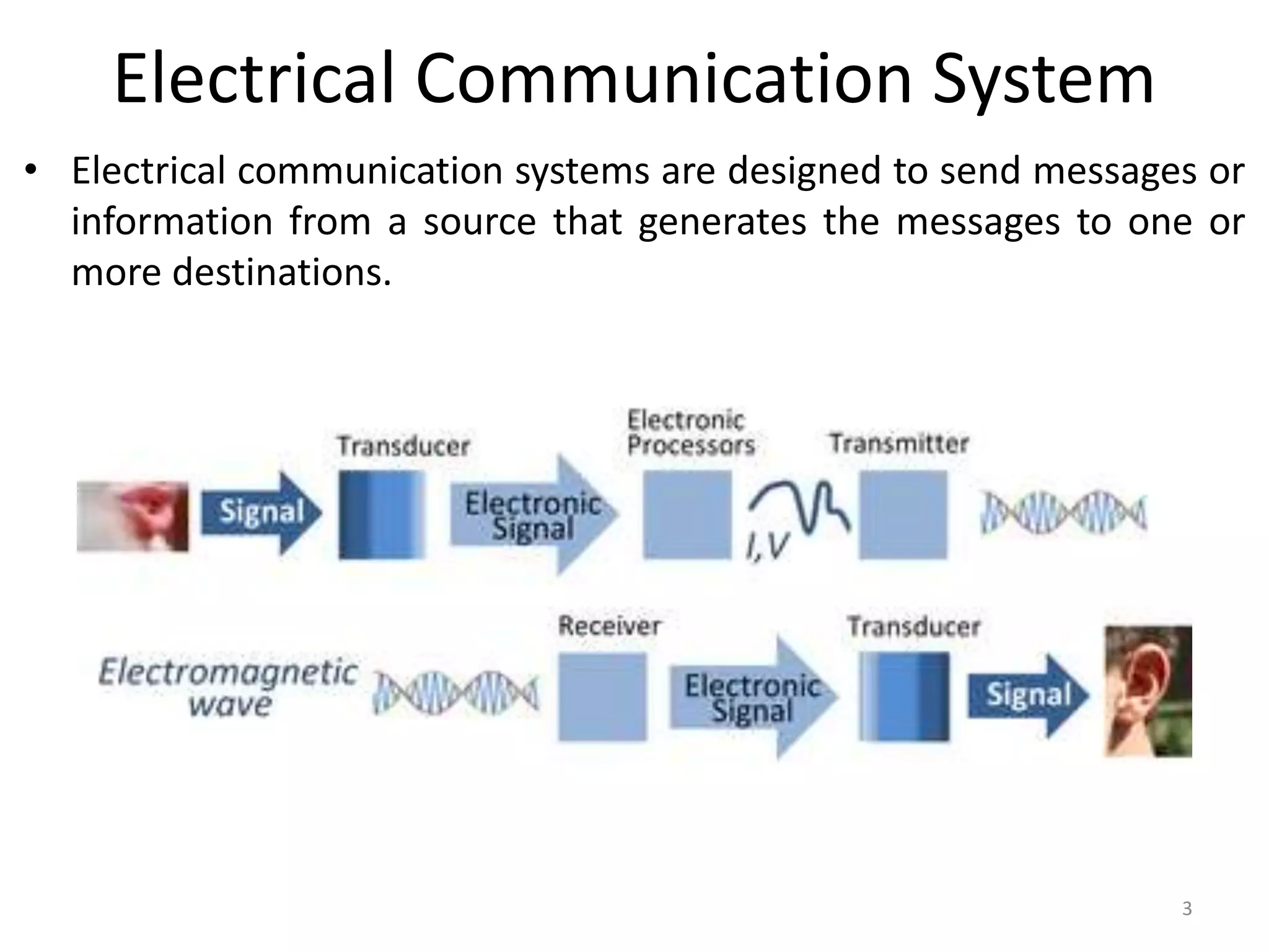
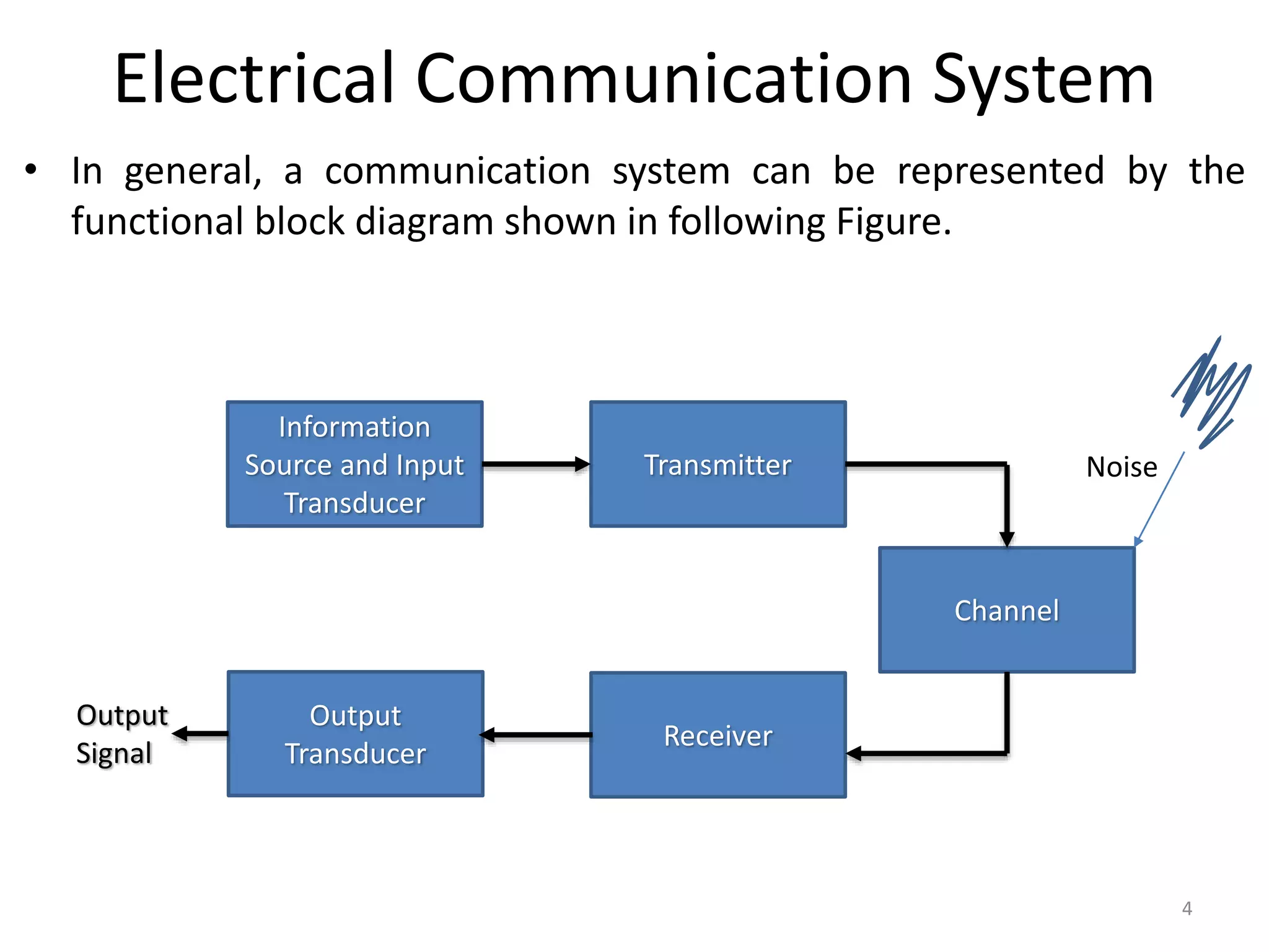
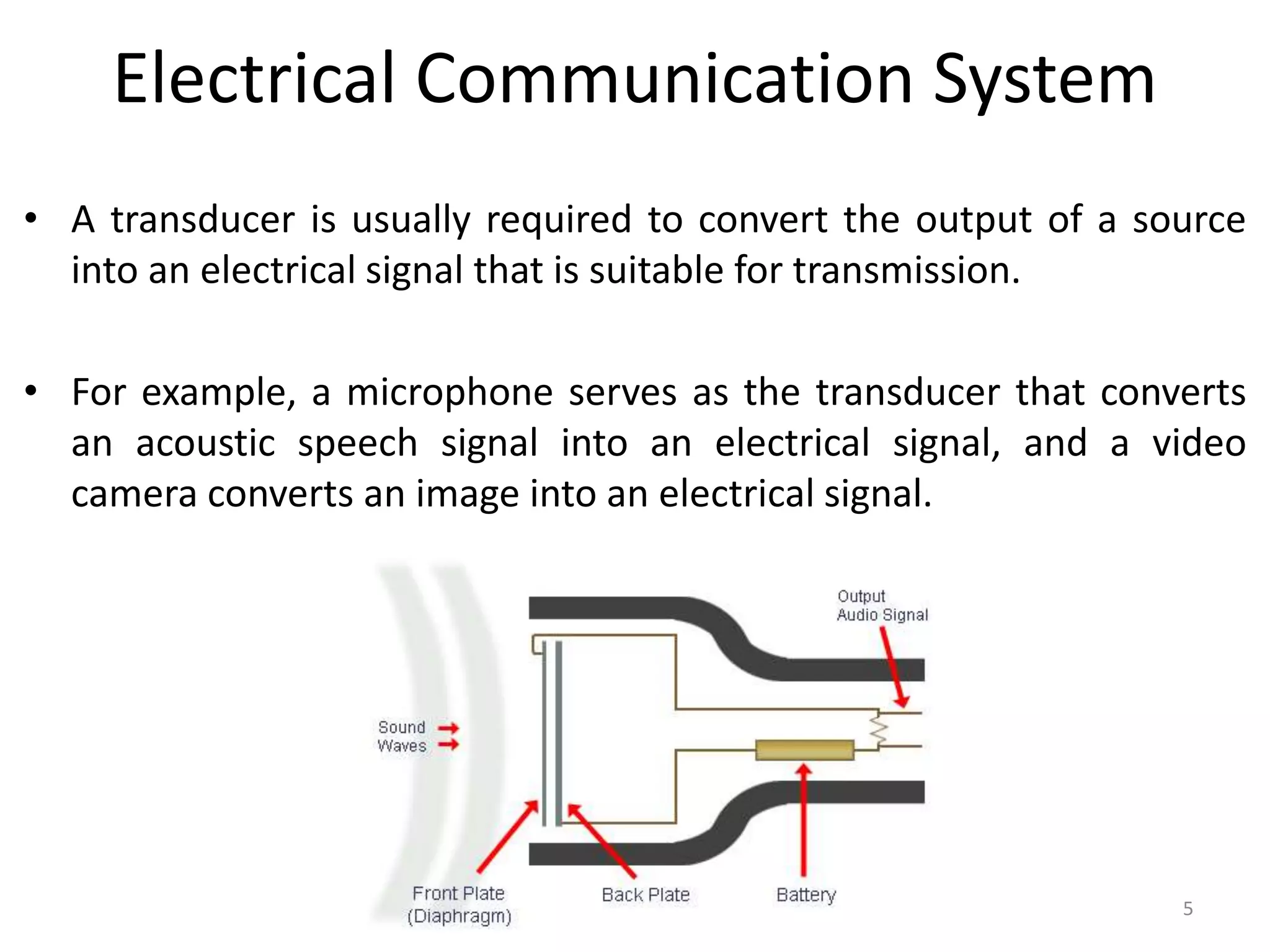
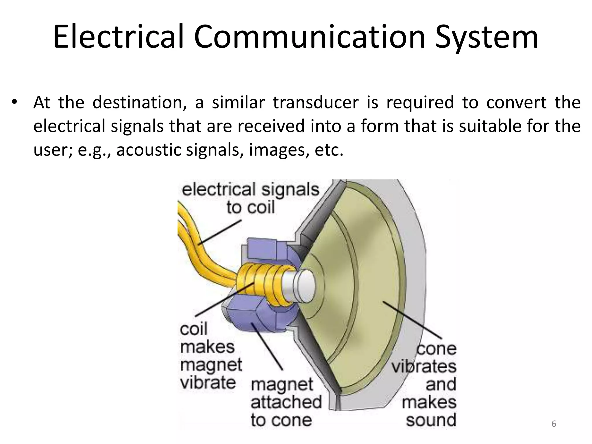
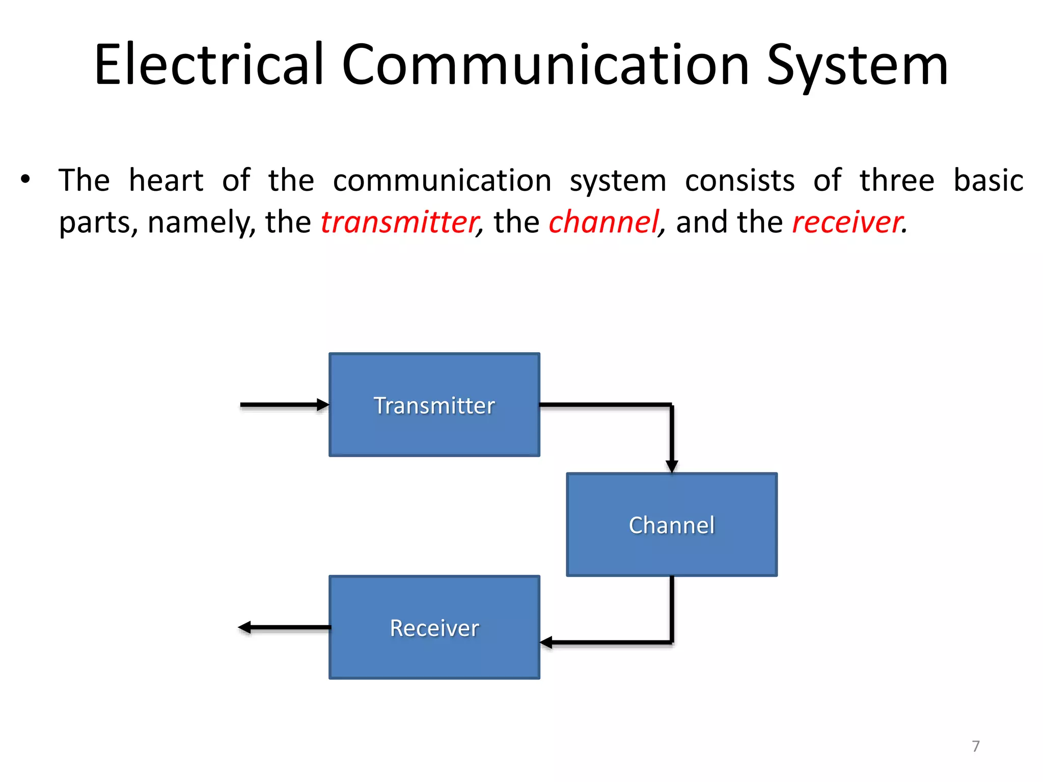
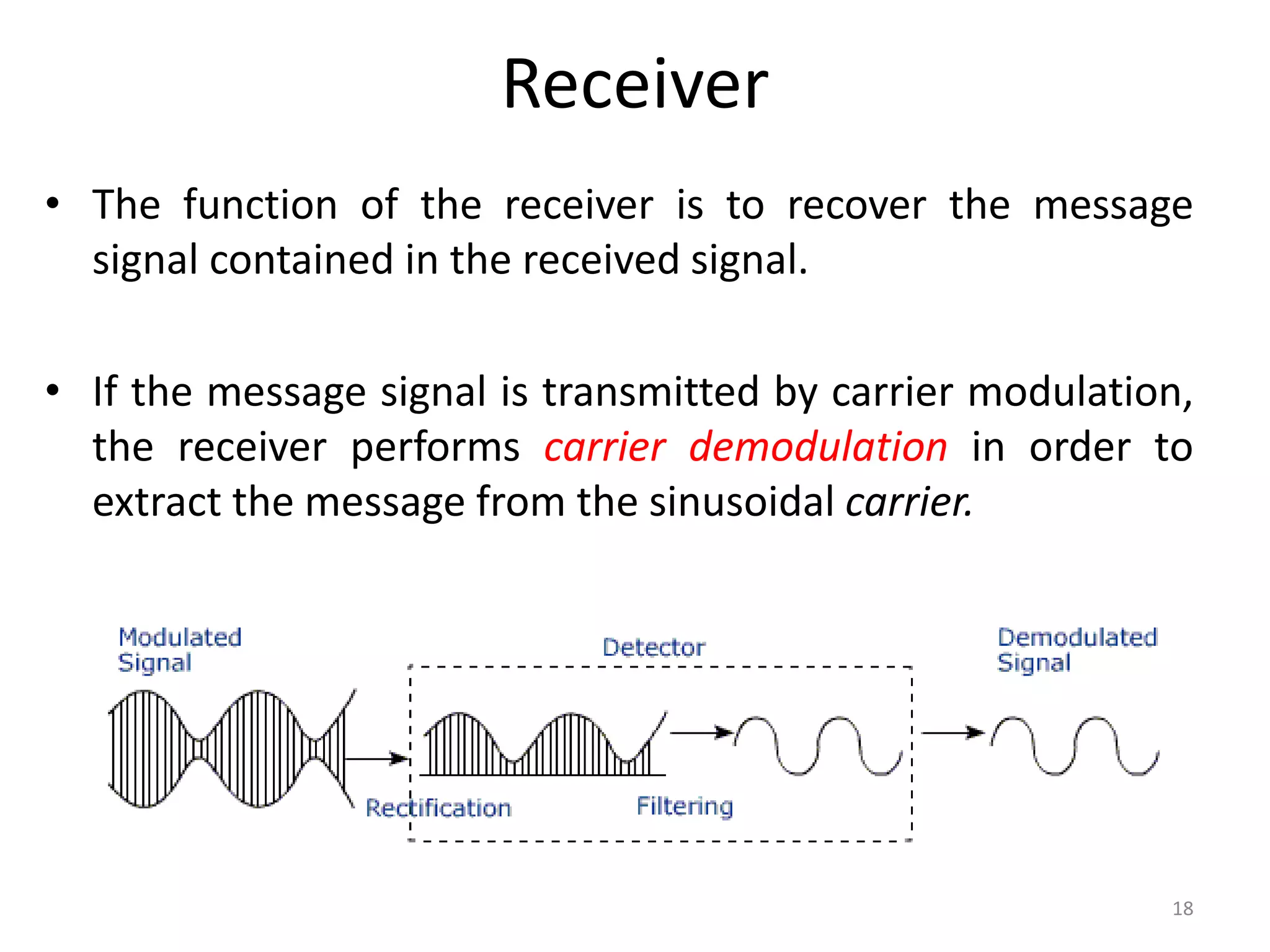
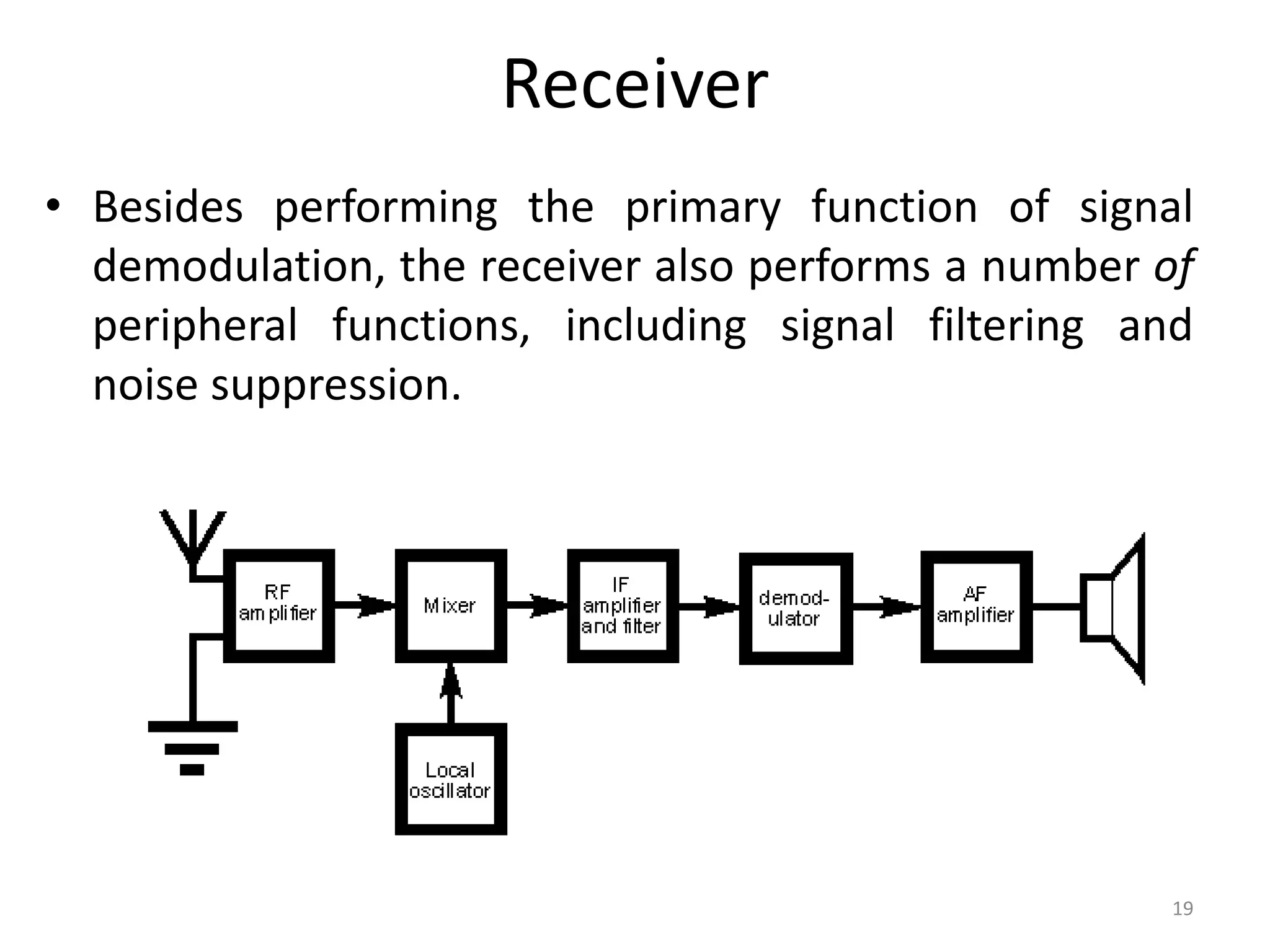
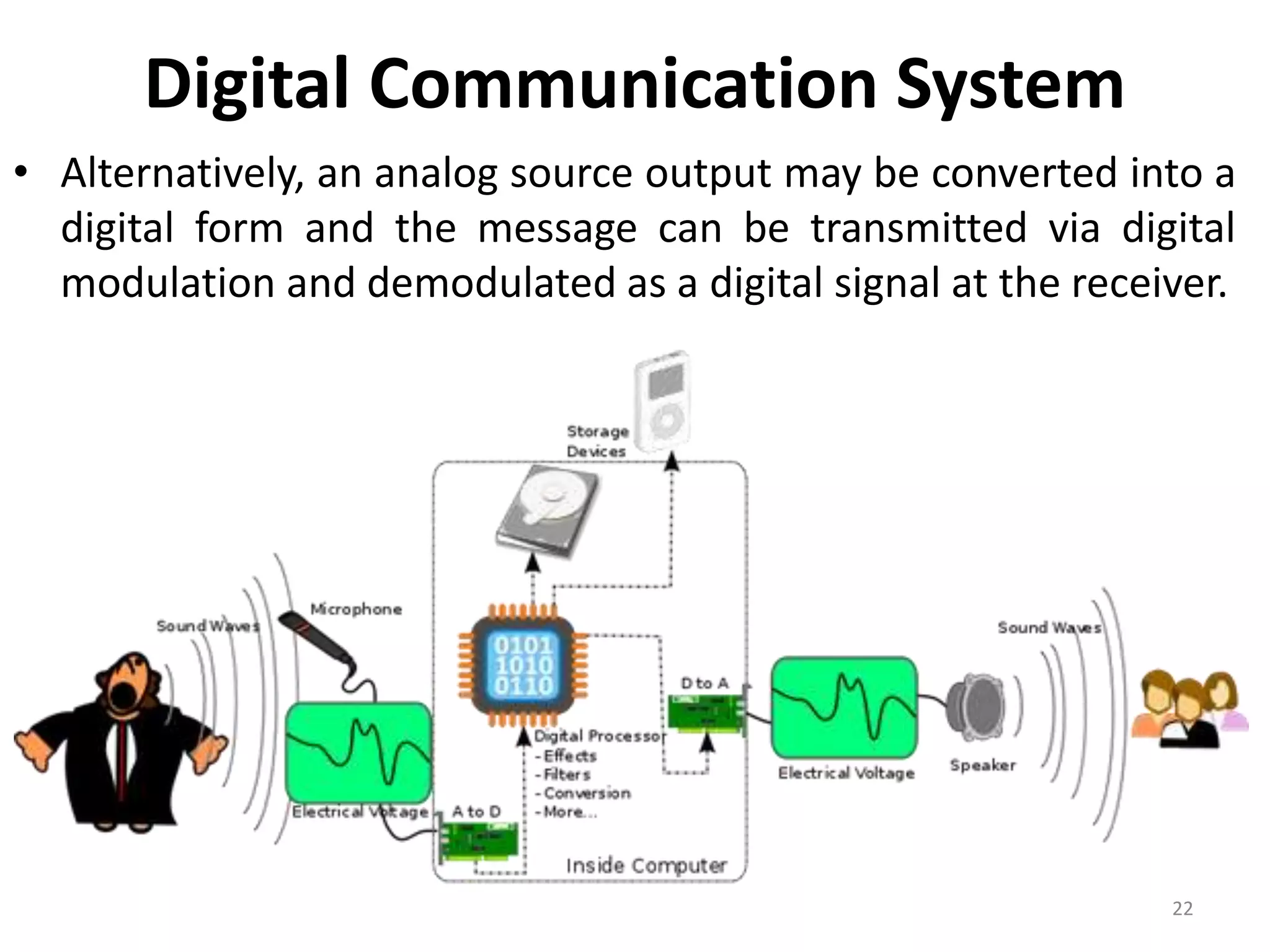
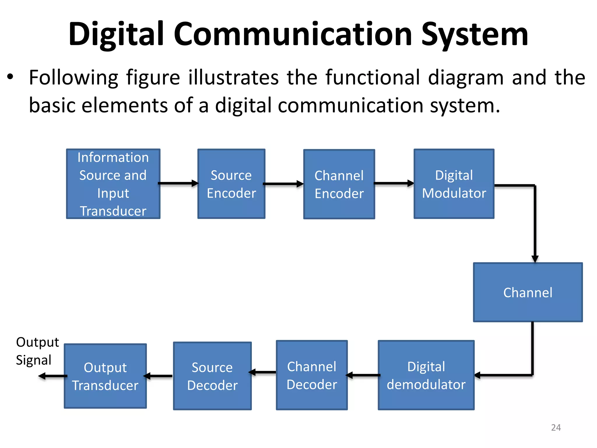
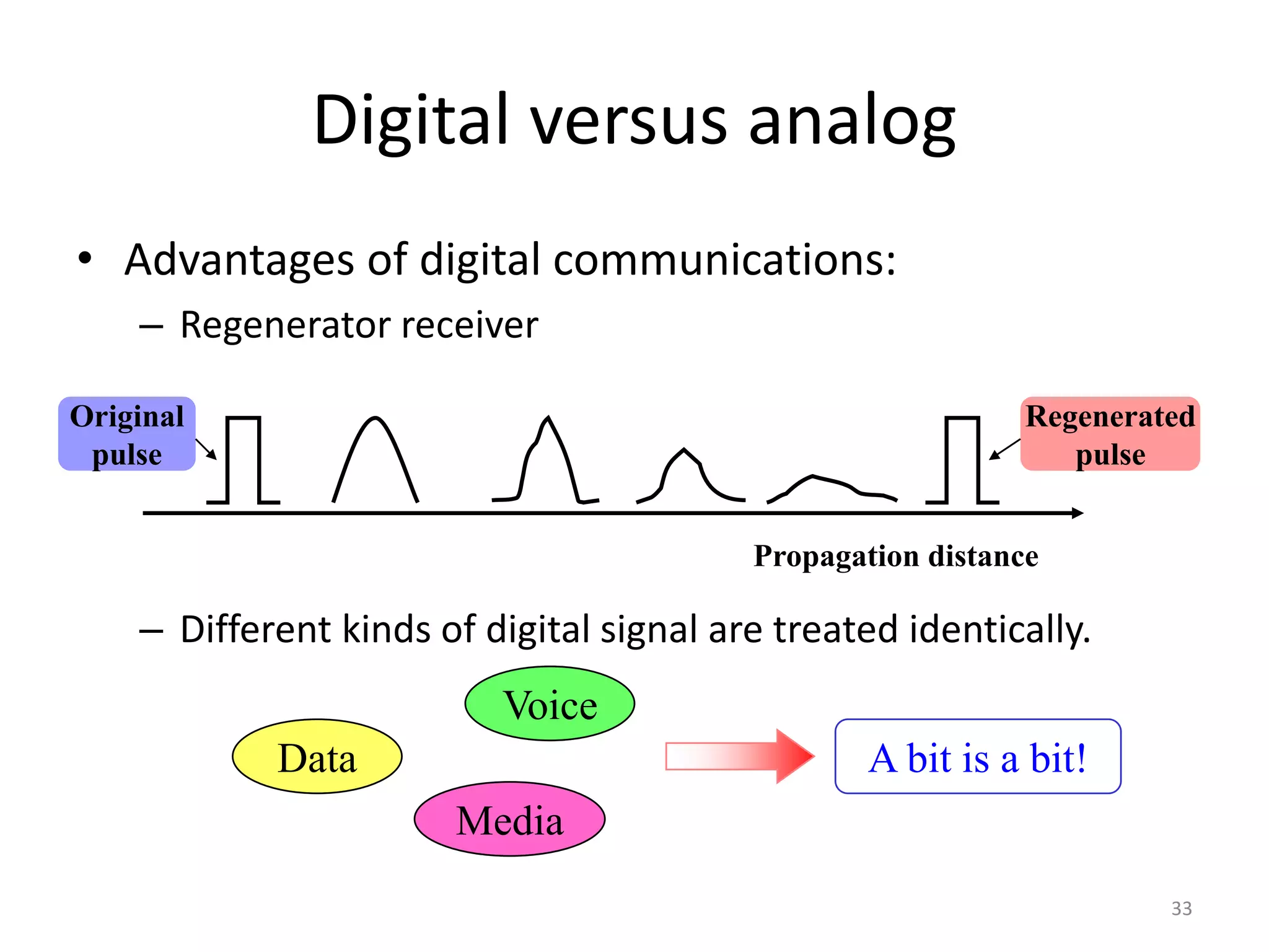
SlideShare a Scribd company logo
Dr. Imtiaz Hussain
Associate Professor (Control Systems),
School of Electrical Engineering
DHA Suffa University, Karachi, Pakistan
email: imtiaz.hussain@dsu.edu.pk
URL :http://imtiazhussainkalwar.weebly.com/
Note: I do not claim any originality in these lectures. The contents of this presentation are
mostly taken from the book Communication Systems, by Simon Haykin and various other
internet sources. 1
Communication Systems (EE-341)
5th Semester (Sec-5A)
Location GF-030
Monday-Wednesday-Friday 11:00 am
Outline
• Elements of Electrical Communication System
– Analog Communication System
– Digital Communication System
• Transmission Media
– Guided Media
– Unguided Media
2
Electrical Communication System
• Electrical communication systems are designed to send messages or
information from a source that generates the messages to one or
more destinations.
3
Electrical Communication System
• In general, a communication system can be represented by the
functional block diagram shown in following Figure.
4
Information
Source and Input
Transducer
Transmitter
Channel
Receiver
Output
Transducer
Output
Signal
Noise
Electrical Communication System
• A transducer is usually required to convert the output of a source
into an electrical signal that is suitable for transmission.
• For example, a microphone serves as the transducer that converts
an acoustic speech signal into an electrical signal, and a video
camera converts an image into an electrical signal.
5
Electrical Communication System
• At the destination, a similar transducer is required to convert the
electrical signals that are received into a form that is suitable for the
user; e.g., acoustic signals, images, etc.
6
Electrical Communication System
• The heart of the communication system consists of three basic
parts, namely, the transmitter, the channel, and the receiver.
7
Transmitter
Channel
Receiver
Transmitter
• The transmitter converts the electrical signal into a form that
is suitable for transmission through the physical channel or
transmission medium.
• For example, in radio and TV broadcast, the Federal
Communications Commission (FCC in USA, PTA, FAB, in
Pakistan) specifies the frequency range for each transmitting
station.
• Hence, the transmitter must translate the information signal
to be transmitted into the appropriate frequency range that
matches the frequency allocation assigned to the transmitter.
• Thus, signals transmitted by multiple radio stations do not
interfere with one another. 8
Transmitter
• In general, the transmitter performs the matching of the
message signal to the channel by a process called
modulation.
• Usually, modulation involves the use of the information
signal to systematically vary either the amplitude,
frequency, or phase of a sinusoidal carrier.
9
Transmitter
• For example, in AM radio broadcast, the information signal
that is transmitted is contained in the amplitude variations of
the sinusoidal carrier, which is the center frequency in the
frequency band allocated to the radio transmitting station.
10
AM Transmission
11
Transmitter
• In FM radio broadcast, the information signal that is
transmitted is contained in the frequency variations of
the sinusoidal carrier.
12
Transmitter
• Thus, through the process of modulation, the
information signal is translated in frequency to match
the allocation of the channel.
• The choice of the type of modulation is based on several
factors, such as:
– amount of bandwidth allocated,
– types of noise and interference that the signal encounters in
transmission over the channel
– electronic devices that are available for signal amplification
prior to transmission.
13
Channel
• The communications channel is the physical
medium that is used to send the signal from the
transmitter to the receiver.
• In wireless transmission, the channel is usually
the atmosphere (free space).
• On the other hand, telephone channels usually
employ a variety of physical media, including
copper wires and optical fiber cables.
14
Channel
• Whatever the physical medium for signal transmission,
the essential feature is that the transmitted signal is
corrupted in a random manner by a variety of possible
mechanisms.
• The most common form of signal degradation comes in
the form of additive noise, which is generated at the
front end of the receiver, where signal amplification is
performed.
• This noise is often called thermal noise.
15
Channel
• In wireless transmission, additional additive
disturbances are man-made noise, and atmospheric
noise picked up by a receiving antenna.
– Automobile ignition noise is an example of man-made
noise.
– Electrical lightning discharges from thunderstorms is an
example of atmospheric noise.
• Interference from other users of the channel is
another form of additive noise that often arises in
both wireless and wireline communication systems.
16
Channel
• In the design of a communication system, the system
designer works with mathematical models that
statistically characterize the signal distortion
encountered on physical channels.
• Often, the statistical description that is used in a
mathematical model is a result of actual empirical
measurements obtained from experiments involving
signal transmission over such channels.
17
Receiver
• The function of the receiver is to recover the message
signal contained in the received signal.
• If the message signal is transmitted by carrier modulation,
the receiver performs carrier demodulation in order to
extract the message from the sinusoidal carrier.
18
Receiver
• Besides performing the primary function of signal
demodulation, the receiver also performs a number of
peripheral functions, including signal filtering and
noise suppression.
19
Receiver
• Since the signal demodulation is performed in the
presence of additive noise and possibly other signal
distortion, the demodulated message signal is
generally degraded to some extent by the presence of
these distortions in the received signal.
• The fidelity of the received message signal is a
function of
– Type of modulation,
– Strength of the additive noise
– Type of any non-additive interference.
20
Digital Communication System
• Up to this point we have described an electrical
communication system in rather broad terms based on the
implicit assumption that the message signal is a continuous
time varying waveform.
• We refer to such continuous-time signal waveforms as analog
signals and to the corresponding information sources that
produce such signals as analog sources.
• Analog signals can be transmitted directly via carrier
modulation over the communication channel and
demodulated accordingly at the receiver.
• We call such a communication system an analog
communication system.
21
Digital Communication System
• Alternatively, an analog source output may be converted into a
digital form and the message can be transmitted via digital
modulation and demodulated as a digital signal at the receiver.
22
Digital Communication System
• There are Some potential advantages to transmitting an
analog signal by means of digital modulation.
• The most important reason is that signal fidelity is better
controlled through digital transmission than analog
transmission.
23
Digital Communication System
• Following figure illustrates the functional diagram and the
basic elements of a digital communication system.
24
Source
Encoder
Channel
Encoder
Channel
Output
Transducer
Source
Decoder
Output
Signal
Information
Source and
Input
Transducer
Digital
Modulator
Digital
demodulator
Channel
Decoder
Digital Communication System
• The process of efficiently converting the output of either an
analog or a digital source into a sequence of binary digits is
called source encoding.
• The sequence of binary digits from the source encoder,
which we call the information sequence is passed to the
channel encoder.
• The purpose of the channel encoder is to introduce, in a
controlled manner, some redundancy in the binary
information sequence which can be used at the receiver to
overcome the effects of noise and interference encountered
in the transmission of the signal through the channel.
25
Source Encoding
• The process of efficiently converting the output of either
an analog or a digital source into a sequence of binary
digits is called source encoding.
26
Channel Encoding
• A major feature of digital data transmission is the myriad
techniques used to protect data or speech through coding.
• Coding adds additional bits to the original payload to
provide a means of protecting the original information.
27
Digital Modulator
• The binary sequence at the output of the channel
encoder is passed to the digital modulator, which serves
as the interface to the communications channel.
28
Digital Modulator
• Since nearly all of the communication channels
encountered in practice are capable of transmitting
electrical signals (waveforms), the primary purpose of the
digital modulator is to map the binary information
sequence into signal waveforms.
29
Digital Demodulator
• At the receiving end of a digital communications system,
the digital demodulator processes the channel-
corrupted transmitted waveform and reduces each
waveform to a single number that represents an
estimate of the transmitted data symbol.
30
Channel Decoder
• Recovery
31
Source Decoder
• As- a final step, when an analog output is desired, the
source decoder accepts the output sequence from the
channel decoder and, from knowledge of the source
encoding method used, attempts to reconstruct the
original signal from the source.
32
33
Digital versus analog
• Advantages of digital communications:
– Regenerator receiver
– Different kinds of digital signal are treated identically.
Data
Voice
Media
Propagation distance
Original
pulse
Regenerated
pulse
A bit is a bit!
END OF LECTURE-2
To download this lecture visit
http://imtiazhussainkalwar.weebly.com/
34

More Related Content

Similar to lecture_2_basics.pptx

Group 1 communication system.pptx
Group 1 communication system.pptxGroup 1 communication system.pptx
Group 1 communication system.pptx
AdwitiyaGoswami
 
Introduction.pdf
Introduction.pdfIntroduction.pdf
Introduction.pdf
Madhumitha Jayaram
 
Communication_System_presentation_Slides.pptx
Communication_System_presentation_Slides.pptxCommunication_System_presentation_Slides.pptx
Communication_System_presentation_Slides.pptx
renur18
 
Data transmission and optical fiber
Data transmission and optical fiberData transmission and optical fiber
Data transmission and optical fiber
YogeshLayalu
 
Chapter1_Lect1.ppt
Chapter1_Lect1.pptChapter1_Lect1.ppt
Chapter1_Lect1.ppt
HasanFarahneh1
 
Chapter1_Lect1.ppt
Chapter1_Lect1.pptChapter1_Lect1.ppt
Chapter1_Lect1.ppt
idrissaeed
 
lecture15.ppt
lecture15.pptlecture15.ppt
lecture15.ppt
DrDeepakBhatia
 
lecture15.ppt
lecture15.pptlecture15.ppt
lecture15.ppt
DrDeepakBhatia
 
Bsnl Training Report
Bsnl Training ReportBsnl Training Report
Bsnl Training Report
Nikhil Kumar
 
Introduction to digital communications
Introduction to digital communicationsIntroduction to digital communications
Introduction to digital communications
Ayaelshiwi
 
chapter-4-Analog-and-Digital-Modulation.ppt
chapter-4-Analog-and-Digital-Modulation.pptchapter-4-Analog-and-Digital-Modulation.ppt
chapter-4-Analog-and-Digital-Modulation.ppt
GeethaPriya555088
 
Chapter 1
Chapter 1Chapter 1
Chapter 1
Fawad Masood
 
Communication systems v1
Communication systems v1Communication systems v1
Communication systems v1
babak danyal
 
1 . introduction to communication system
1 . introduction to communication system1 . introduction to communication system
1 . introduction to communication system
abhijitjnec
 
PCM_DC_PPT.pdf
PCM_DC_PPT.pdfPCM_DC_PPT.pdf
PCM_DC_PPT.pdf
ArunKumar674066
 
Chapter01.ppt
Chapter01.pptChapter01.ppt
Chapter01.ppt
ssuser00f231
 
Basics of analog communication system
Basics of analog communication systemBasics of analog communication system
Basics of analog communication system
swatihalunde
 
Digital communication system
Digital communication systemDigital communication system
Digital communication system
babak danyal
 
Communication System Basics
Communication System BasicsCommunication System Basics
Communication System Basics
A B Shinde
 
telecom fundamentals.pptx
telecom fundamentals.pptxtelecom fundamentals.pptx
telecom fundamentals.pptx
gebreyesusweldegebri2
 

Similar to lecture_2_basics.pptx (20)

Group 1 communication system.pptx
Group 1 communication system.pptxGroup 1 communication system.pptx
Group 1 communication system.pptx
 
Introduction.pdf
Introduction.pdfIntroduction.pdf
Introduction.pdf
 
Communication_System_presentation_Slides.pptx
Communication_System_presentation_Slides.pptxCommunication_System_presentation_Slides.pptx
Communication_System_presentation_Slides.pptx
 
Data transmission and optical fiber
Data transmission and optical fiberData transmission and optical fiber
Data transmission and optical fiber
 
Chapter1_Lect1.ppt
Chapter1_Lect1.pptChapter1_Lect1.ppt
Chapter1_Lect1.ppt
 
Chapter1_Lect1.ppt
Chapter1_Lect1.pptChapter1_Lect1.ppt
Chapter1_Lect1.ppt
 
lecture15.ppt
lecture15.pptlecture15.ppt
lecture15.ppt
 
lecture15.ppt
lecture15.pptlecture15.ppt
lecture15.ppt
 
Bsnl Training Report
Bsnl Training ReportBsnl Training Report
Bsnl Training Report
 
Introduction to digital communications
Introduction to digital communicationsIntroduction to digital communications
Introduction to digital communications
 
chapter-4-Analog-and-Digital-Modulation.ppt
chapter-4-Analog-and-Digital-Modulation.pptchapter-4-Analog-and-Digital-Modulation.ppt
chapter-4-Analog-and-Digital-Modulation.ppt
 
Chapter 1
Chapter 1Chapter 1
Chapter 1
 
Communication systems v1
Communication systems v1Communication systems v1
Communication systems v1
 
1 . introduction to communication system
1 . introduction to communication system1 . introduction to communication system
1 . introduction to communication system
 
PCM_DC_PPT.pdf
PCM_DC_PPT.pdfPCM_DC_PPT.pdf
PCM_DC_PPT.pdf
 
Chapter01.ppt
Chapter01.pptChapter01.ppt
Chapter01.ppt
 
Basics of analog communication system
Basics of analog communication systemBasics of analog communication system
Basics of analog communication system
 
Digital communication system
Digital communication systemDigital communication system
Digital communication system
 
Communication System Basics
Communication System BasicsCommunication System Basics
Communication System Basics
 
telecom fundamentals.pptx
telecom fundamentals.pptxtelecom fundamentals.pptx
telecom fundamentals.pptx
 

Recently uploaded

KuberTENes Birthday Bash Guadalajara - K8sGPT first impressions
KuberTENes Birthday Bash Guadalajara - K8sGPT first impressionsKuberTENes Birthday Bash Guadalajara - K8sGPT first impressions
KuberTENes Birthday Bash Guadalajara - K8sGPT first impressions
Victor Morales
 
22CYT12-Unit-V-E Waste and its Management.ppt
22CYT12-Unit-V-E Waste and its Management.ppt22CYT12-Unit-V-E Waste and its Management.ppt
22CYT12-Unit-V-E Waste and its Management.ppt
KrishnaveniKrishnara1
 
ACRP 4-09 Risk Assessment Method to Support Modification of Airfield Separat...
ACRP 4-09 Risk Assessment Method to Support Modification of Airfield Separat...ACRP 4-09 Risk Assessment Method to Support Modification of Airfield Separat...
ACRP 4-09 Risk Assessment Method to Support Modification of Airfield Separat...
Mukeshwaran Balu
 
哪里办理(csu毕业证书)查尔斯特大学毕业证硕士学历原版一模一样
哪里办理(csu毕业证书)查尔斯特大学毕业证硕士学历原版一模一样哪里办理(csu毕业证书)查尔斯特大学毕业证硕士学历原版一模一样
哪里办理(csu毕业证书)查尔斯特大学毕业证硕士学历原版一模一样
insn4465
 
New techniques for characterising damage in rock slopes.pdf
New techniques for characterising damage in rock slopes.pdfNew techniques for characterising damage in rock slopes.pdf
New techniques for characterising damage in rock slopes.pdf
wisnuprabawa3
 
Technical Drawings introduction to drawing of prisms
Technical Drawings introduction to drawing of prismsTechnical Drawings introduction to drawing of prisms
Technical Drawings introduction to drawing of prisms
heavyhaig
 
Low power architecture of logic gates using adiabatic techniques
Low power architecture of logic gates using adiabatic techniquesLow power architecture of logic gates using adiabatic techniques
Low power architecture of logic gates using adiabatic techniques
nooriasukmaningtyas
 
Wearable antenna for antenna applications
Wearable antenna for antenna applicationsWearable antenna for antenna applications
Wearable antenna for antenna applications
Madhumitha Jayaram
 
Harnessing WebAssembly for Real-time Stateless Streaming Pipelines
Harnessing WebAssembly for Real-time Stateless Streaming PipelinesHarnessing WebAssembly for Real-time Stateless Streaming Pipelines
Harnessing WebAssembly for Real-time Stateless Streaming Pipelines
Christina Lin
 
Properties Railway Sleepers and Test.pptx
Properties Railway Sleepers and Test.pptxProperties Railway Sleepers and Test.pptx
Properties Railway Sleepers and Test.pptx
MDSABBIROJJAMANPAYEL
 
Advanced control scheme of doubly fed induction generator for wind turbine us...
Advanced control scheme of doubly fed induction generator for wind turbine us...Advanced control scheme of doubly fed induction generator for wind turbine us...
Advanced control scheme of doubly fed induction generator for wind turbine us...
IJECEIAES
 
Heat Resistant Concrete Presentation ppt
Heat Resistant Concrete Presentation pptHeat Resistant Concrete Presentation ppt
Heat Resistant Concrete Presentation ppt
mamunhossenbd75
 
2. Operations Strategy in a Global Environment.ppt
2. Operations Strategy in a Global Environment.ppt2. Operations Strategy in a Global Environment.ppt
2. Operations Strategy in a Global Environment.ppt
PuktoonEngr
 
5214-1693458878915-Unit 6 2023 to 2024 academic year assignment (AutoRecovere...
5214-1693458878915-Unit 6 2023 to 2024 academic year assignment (AutoRecovere...5214-1693458878915-Unit 6 2023 to 2024 academic year assignment (AutoRecovere...
5214-1693458878915-Unit 6 2023 to 2024 academic year assignment (AutoRecovere...
ihlasbinance2003
 
Series of visio cisco devices Cisco_Icons.ppt
Series of visio cisco devices Cisco_Icons.pptSeries of visio cisco devices Cisco_Icons.ppt
Series of visio cisco devices Cisco_Icons.ppt
PauloRodrigues104553
 
A SYSTEMATIC RISK ASSESSMENT APPROACH FOR SECURING THE SMART IRRIGATION SYSTEMS
A SYSTEMATIC RISK ASSESSMENT APPROACH FOR SECURING THE SMART IRRIGATION SYSTEMSA SYSTEMATIC RISK ASSESSMENT APPROACH FOR SECURING THE SMART IRRIGATION SYSTEMS
A SYSTEMATIC RISK ASSESSMENT APPROACH FOR SECURING THE SMART IRRIGATION SYSTEMS
IJNSA Journal
 
DfMAy 2024 - key insights and contributions
DfMAy 2024 - key insights and contributionsDfMAy 2024 - key insights and contributions
DfMAy 2024 - key insights and contributions
gestioneergodomus
 
CSM Cloud Service Management Presentarion
CSM Cloud Service Management PresentarionCSM Cloud Service Management Presentarion
CSM Cloud Service Management Presentarion
rpskprasana
 
bank management system in java and mysql report1.pdf
bank management system in java and mysql report1.pdfbank management system in java and mysql report1.pdf
bank management system in java and mysql report1.pdf
Divyam548318
 
132/33KV substation case study Presentation
132/33KV substation case study Presentation132/33KV substation case study Presentation
132/33KV substation case study Presentation
kandramariana6
 

Recently uploaded (20)

KuberTENes Birthday Bash Guadalajara - K8sGPT first impressions
KuberTENes Birthday Bash Guadalajara - K8sGPT first impressionsKuberTENes Birthday Bash Guadalajara - K8sGPT first impressions
KuberTENes Birthday Bash Guadalajara - K8sGPT first impressions
 
22CYT12-Unit-V-E Waste and its Management.ppt
22CYT12-Unit-V-E Waste and its Management.ppt22CYT12-Unit-V-E Waste and its Management.ppt
22CYT12-Unit-V-E Waste and its Management.ppt
 
ACRP 4-09 Risk Assessment Method to Support Modification of Airfield Separat...
ACRP 4-09 Risk Assessment Method to Support Modification of Airfield Separat...ACRP 4-09 Risk Assessment Method to Support Modification of Airfield Separat...
ACRP 4-09 Risk Assessment Method to Support Modification of Airfield Separat...
 
哪里办理(csu毕业证书)查尔斯特大学毕业证硕士学历原版一模一样
哪里办理(csu毕业证书)查尔斯特大学毕业证硕士学历原版一模一样哪里办理(csu毕业证书)查尔斯特大学毕业证硕士学历原版一模一样
哪里办理(csu毕业证书)查尔斯特大学毕业证硕士学历原版一模一样
 
New techniques for characterising damage in rock slopes.pdf
New techniques for characterising damage in rock slopes.pdfNew techniques for characterising damage in rock slopes.pdf
New techniques for characterising damage in rock slopes.pdf
 
Technical Drawings introduction to drawing of prisms
Technical Drawings introduction to drawing of prismsTechnical Drawings introduction to drawing of prisms
Technical Drawings introduction to drawing of prisms
 
Low power architecture of logic gates using adiabatic techniques
Low power architecture of logic gates using adiabatic techniquesLow power architecture of logic gates using adiabatic techniques
Low power architecture of logic gates using adiabatic techniques
 
Wearable antenna for antenna applications
Wearable antenna for antenna applicationsWearable antenna for antenna applications
Wearable antenna for antenna applications
 
Harnessing WebAssembly for Real-time Stateless Streaming Pipelines
Harnessing WebAssembly for Real-time Stateless Streaming PipelinesHarnessing WebAssembly for Real-time Stateless Streaming Pipelines
Harnessing WebAssembly for Real-time Stateless Streaming Pipelines
 
Properties Railway Sleepers and Test.pptx
Properties Railway Sleepers and Test.pptxProperties Railway Sleepers and Test.pptx
Properties Railway Sleepers and Test.pptx
 
Advanced control scheme of doubly fed induction generator for wind turbine us...
Advanced control scheme of doubly fed induction generator for wind turbine us...Advanced control scheme of doubly fed induction generator for wind turbine us...
Advanced control scheme of doubly fed induction generator for wind turbine us...
 
Heat Resistant Concrete Presentation ppt
Heat Resistant Concrete Presentation pptHeat Resistant Concrete Presentation ppt
Heat Resistant Concrete Presentation ppt
 
2. Operations Strategy in a Global Environment.ppt
2. Operations Strategy in a Global Environment.ppt2. Operations Strategy in a Global Environment.ppt
2. Operations Strategy in a Global Environment.ppt
 
5214-1693458878915-Unit 6 2023 to 2024 academic year assignment (AutoRecovere...
5214-1693458878915-Unit 6 2023 to 2024 academic year assignment (AutoRecovere...5214-1693458878915-Unit 6 2023 to 2024 academic year assignment (AutoRecovere...
5214-1693458878915-Unit 6 2023 to 2024 academic year assignment (AutoRecovere...
 
Series of visio cisco devices Cisco_Icons.ppt
Series of visio cisco devices Cisco_Icons.pptSeries of visio cisco devices Cisco_Icons.ppt
Series of visio cisco devices Cisco_Icons.ppt
 
A SYSTEMATIC RISK ASSESSMENT APPROACH FOR SECURING THE SMART IRRIGATION SYSTEMS
A SYSTEMATIC RISK ASSESSMENT APPROACH FOR SECURING THE SMART IRRIGATION SYSTEMSA SYSTEMATIC RISK ASSESSMENT APPROACH FOR SECURING THE SMART IRRIGATION SYSTEMS
A SYSTEMATIC RISK ASSESSMENT APPROACH FOR SECURING THE SMART IRRIGATION SYSTEMS
 
DfMAy 2024 - key insights and contributions
DfMAy 2024 - key insights and contributionsDfMAy 2024 - key insights and contributions
DfMAy 2024 - key insights and contributions
 
CSM Cloud Service Management Presentarion
CSM Cloud Service Management PresentarionCSM Cloud Service Management Presentarion
CSM Cloud Service Management Presentarion
 
bank management system in java and mysql report1.pdf
bank management system in java and mysql report1.pdfbank management system in java and mysql report1.pdf
bank management system in java and mysql report1.pdf
 
132/33KV substation case study Presentation
132/33KV substation case study Presentation132/33KV substation case study Presentation
132/33KV substation case study Presentation
 

lecture_2_basics.pptx

  • 1. Dr. Imtiaz Hussain Associate Professor (Control Systems), School of Electrical Engineering DHA Suffa University, Karachi, Pakistan email: imtiaz.hussain@dsu.edu.pk URL :http://imtiazhussainkalwar.weebly.com/ Note: I do not claim any originality in these lectures. The contents of this presentation are mostly taken from the book Communication Systems, by Simon Haykin and various other internet sources. 1 Communication Systems (EE-341) 5th Semester (Sec-5A) Location GF-030 Monday-Wednesday-Friday 11:00 am
  • 2. Outline • Elements of Electrical Communication System – Analog Communication System – Digital Communication System • Transmission Media – Guided Media – Unguided Media 2
  • 3. Electrical Communication System • Electrical communication systems are designed to send messages or information from a source that generates the messages to one or more destinations. 3
  • 4. Electrical Communication System • In general, a communication system can be represented by the functional block diagram shown in following Figure. 4 Information Source and Input Transducer Transmitter Channel Receiver Output Transducer Output Signal Noise
  • 5. Electrical Communication System • A transducer is usually required to convert the output of a source into an electrical signal that is suitable for transmission. • For example, a microphone serves as the transducer that converts an acoustic speech signal into an electrical signal, and a video camera converts an image into an electrical signal. 5
  • 6. Electrical Communication System • At the destination, a similar transducer is required to convert the electrical signals that are received into a form that is suitable for the user; e.g., acoustic signals, images, etc. 6
  • 7. Electrical Communication System • The heart of the communication system consists of three basic parts, namely, the transmitter, the channel, and the receiver. 7 Transmitter Channel Receiver
  • 8. Transmitter • The transmitter converts the electrical signal into a form that is suitable for transmission through the physical channel or transmission medium. • For example, in radio and TV broadcast, the Federal Communications Commission (FCC in USA, PTA, FAB, in Pakistan) specifies the frequency range for each transmitting station. • Hence, the transmitter must translate the information signal to be transmitted into the appropriate frequency range that matches the frequency allocation assigned to the transmitter. • Thus, signals transmitted by multiple radio stations do not interfere with one another. 8
  • 9. Transmitter • In general, the transmitter performs the matching of the message signal to the channel by a process called modulation. • Usually, modulation involves the use of the information signal to systematically vary either the amplitude, frequency, or phase of a sinusoidal carrier. 9
  • 10. Transmitter • For example, in AM radio broadcast, the information signal that is transmitted is contained in the amplitude variations of the sinusoidal carrier, which is the center frequency in the frequency band allocated to the radio transmitting station. 10
  • 12. Transmitter • In FM radio broadcast, the information signal that is transmitted is contained in the frequency variations of the sinusoidal carrier. 12
  • 13. Transmitter • Thus, through the process of modulation, the information signal is translated in frequency to match the allocation of the channel. • The choice of the type of modulation is based on several factors, such as: – amount of bandwidth allocated, – types of noise and interference that the signal encounters in transmission over the channel – electronic devices that are available for signal amplification prior to transmission. 13
  • 14. Channel • The communications channel is the physical medium that is used to send the signal from the transmitter to the receiver. • In wireless transmission, the channel is usually the atmosphere (free space). • On the other hand, telephone channels usually employ a variety of physical media, including copper wires and optical fiber cables. 14
  • 15. Channel • Whatever the physical medium for signal transmission, the essential feature is that the transmitted signal is corrupted in a random manner by a variety of possible mechanisms. • The most common form of signal degradation comes in the form of additive noise, which is generated at the front end of the receiver, where signal amplification is performed. • This noise is often called thermal noise. 15
  • 16. Channel • In wireless transmission, additional additive disturbances are man-made noise, and atmospheric noise picked up by a receiving antenna. – Automobile ignition noise is an example of man-made noise. – Electrical lightning discharges from thunderstorms is an example of atmospheric noise. • Interference from other users of the channel is another form of additive noise that often arises in both wireless and wireline communication systems. 16
  • 17. Channel • In the design of a communication system, the system designer works with mathematical models that statistically characterize the signal distortion encountered on physical channels. • Often, the statistical description that is used in a mathematical model is a result of actual empirical measurements obtained from experiments involving signal transmission over such channels. 17
  • 18. Receiver • The function of the receiver is to recover the message signal contained in the received signal. • If the message signal is transmitted by carrier modulation, the receiver performs carrier demodulation in order to extract the message from the sinusoidal carrier. 18
  • 19. Receiver • Besides performing the primary function of signal demodulation, the receiver also performs a number of peripheral functions, including signal filtering and noise suppression. 19
  • 20. Receiver • Since the signal demodulation is performed in the presence of additive noise and possibly other signal distortion, the demodulated message signal is generally degraded to some extent by the presence of these distortions in the received signal. • The fidelity of the received message signal is a function of – Type of modulation, – Strength of the additive noise – Type of any non-additive interference. 20
  • 21. Digital Communication System • Up to this point we have described an electrical communication system in rather broad terms based on the implicit assumption that the message signal is a continuous time varying waveform. • We refer to such continuous-time signal waveforms as analog signals and to the corresponding information sources that produce such signals as analog sources. • Analog signals can be transmitted directly via carrier modulation over the communication channel and demodulated accordingly at the receiver. • We call such a communication system an analog communication system. 21
  • 22. Digital Communication System • Alternatively, an analog source output may be converted into a digital form and the message can be transmitted via digital modulation and demodulated as a digital signal at the receiver. 22
  • 23. Digital Communication System • There are Some potential advantages to transmitting an analog signal by means of digital modulation. • The most important reason is that signal fidelity is better controlled through digital transmission than analog transmission. 23
  • 24. Digital Communication System • Following figure illustrates the functional diagram and the basic elements of a digital communication system. 24 Source Encoder Channel Encoder Channel Output Transducer Source Decoder Output Signal Information Source and Input Transducer Digital Modulator Digital demodulator Channel Decoder
  • 25. Digital Communication System • The process of efficiently converting the output of either an analog or a digital source into a sequence of binary digits is called source encoding. • The sequence of binary digits from the source encoder, which we call the information sequence is passed to the channel encoder. • The purpose of the channel encoder is to introduce, in a controlled manner, some redundancy in the binary information sequence which can be used at the receiver to overcome the effects of noise and interference encountered in the transmission of the signal through the channel. 25
  • 26. Source Encoding • The process of efficiently converting the output of either an analog or a digital source into a sequence of binary digits is called source encoding. 26
  • 27. Channel Encoding • A major feature of digital data transmission is the myriad techniques used to protect data or speech through coding. • Coding adds additional bits to the original payload to provide a means of protecting the original information. 27
  • 28. Digital Modulator • The binary sequence at the output of the channel encoder is passed to the digital modulator, which serves as the interface to the communications channel. 28
  • 29. Digital Modulator • Since nearly all of the communication channels encountered in practice are capable of transmitting electrical signals (waveforms), the primary purpose of the digital modulator is to map the binary information sequence into signal waveforms. 29
  • 30. Digital Demodulator • At the receiving end of a digital communications system, the digital demodulator processes the channel- corrupted transmitted waveform and reduces each waveform to a single number that represents an estimate of the transmitted data symbol. 30
  • 32. Source Decoder • As- a final step, when an analog output is desired, the source decoder accepts the output sequence from the channel decoder and, from knowledge of the source encoding method used, attempts to reconstruct the original signal from the source. 32
  • 33. 33 Digital versus analog • Advantages of digital communications: – Regenerator receiver – Different kinds of digital signal are treated identically. Data Voice Media Propagation distance Original pulse Regenerated pulse A bit is a bit!
  • 34. END OF LECTURE-2 To download this lecture visit http://imtiazhussainkalwar.weebly.com/ 34