CT coronary Angiography-CT
calcium scoring & Myocardial
Imaging
Presented by
DARSHAN BS
MSc MEDICAL IMAGING TECHNOLOGY
KIDWAI MEMORIAL INSTITUTE OF ONCOLOGY BANGALORE
Coronary Arteries
• Thecoronary arteries are vessels that course through the epicardial
fat to supply the myocardium with oxygenated blood
• it is imperative to distinguish benign variants from congenital
abnormalities that can lead to a compromise of blood flow with
subsequent myocardial ischemia, infarction, or sudden cardiac death.
4.
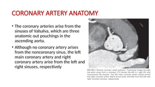
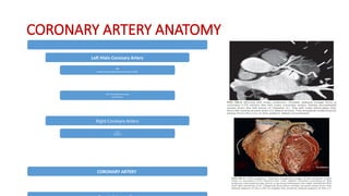
CORONARY ARTERY ANATOMY
•The coronary arteries arise from the
sinuses of Valsalva, which are three
anatomic out pouchings in the
ascending aorta.
• Although no coronary artery arises
from the noncoronary sinus, the left
main coronary artery and right
coronary artery arise from the left and
right sinuses, respectively
5.
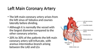
Left Main CoronaryArtery
• The left main coronary artery arises from
the left sinus of Valsalva and courses
laterally before dividing.
• Although it is normally the vessel with
the largest diameter compared to the
other coronary arteries.
• 20% to 30% of the patients the left main
coronary artery will trifurcate, with
aramus intermedius branch arising
between the LAD and LCx
THE RIGHT CORONARYARTERY (RCA)
• The right coronary artery (RCA) arises from the anterior-facing right
sinus of Valsalva
• right dominant the RCA is a large vessel that courses anteriorly in the right
AV groove. Similar to the LAD the RCA is divided into three territories
• The proximal RCA is defined as the ostium of the RCA to half the distance
to the acute margin of the heart. The mid-RCA is defined as the end of the
proximal RCA to the acute margin of the heart, and the distal RCA is
defined as the end of the mid-RCA to the origin of the posterior
descending artery.
8.
CARDIAC CT
• optimizeimage quality, it is critical to properly prepare the patient
and select the appropriate imaging protocol that takes into account the
indication for the study.
• Prior to the scan, it is important to explain the procedure to the
patient, determine that there are no contraindications to
premedication or intravenous (IV) contrast, and coach the patient on
breath holding
9.
INDICATION
• cardiac CTapplications include quantitative assessment of
• coronary artery calcifications,
• ventricular function assessment,
• coronary angiography assessment of pulmonary veins,
• cardiac masses and pericardial disease, and
• coronary artery bypass grafts
• CORONARY ARTERY ANOMALIES(anomalous coronary anatomy is best
visualized with electrocardiographically(ECG)-gated CT angiography (CTA),
the improved temporal resolution of modern scanners often allows for
basic assessment of coronaryanatomy even on nongated thoracic CT
scans.)
10.
Patient Preparation
• Multipleinvestigators have shown that the best images are obtained in the setting of a
low heart rate, ideally below 65 beats per minute
(bpm).
• MDCT scanners that provide faster temporal resolution may permit adequate images at
higher heart rates.
• The contrast injection for coronary CTA is typically performed
• 60 to 80 mL of a highly concentrated iodine solution (300-400 mg/dL)
• at a flow rate of 5 to 6 mL/sec.
• For the latter part of the injection, iodine solution may be diluted with saline to
decrease attenuation in the RV, which reduces artifact in the RCA system.
• A saline bolus is added at the end to facilitate transit of the contrast bolus and
eliminate artifacts in the highly concentrated contrast in the superior vena cava.
11.
Technical Requirements
• Essentiallythese steps include the following:
1. Patient preparation
2. Acquisition parameters
3. Contrast medium administration
4. Image postprocessing techniques
12.
THE ACQUISITION PARAMETERS
•include the
• scan speed,
• the pitch, (pitch of 1.5, and a gantry rotation time of 0.5 seconds, a 100-
mm volume of tissue can be scanned in 9 seconds, while for a 16-slice
MSCT scanner with the same pitch and rotation time and at a slice width
of 0.75 mm, the 100-mm volume can be scanned in 3 seconds.
• the spatial resolution needed, (64-slice scanner with a 0.6-mm detector
element is 0.6 mm to 0.7 mm.)
• Contrast material administration,
• the image reconstruction algorithm
13.
CT SCANNING METHODS
•The initial use of CT technology to evaluate the coronary arteries
primarily involved assessing coronary artery calcium and was gathered
used electron beam CT (EBCT), a technology with stationary components
that permitted a high-temporal-resolution solution needed to freeze
physiologic coronary artery motion.
• A minimum requirement for coronary CTA is a 64-slice scanner, and
there are a number of scanners that meet or exceed this threshold.
• Scanner configurations range from 64 to 320 slices,
• consist of 1- or 2-tube configurations (i.e., single or dual source),
14.
• permit spatialresolution in the 0.5-mm range for all 3 planes, and have
temporal resolution as rapid as 66 milliseconds.
• There has also been substantial advancement in detector and other hardware
technology as well as software.
• The focus on radiation dose reduction has led to meaningful innovations such as
introduction of increasingly powerful iterative reconstruction techniques and
• other valuable automated or selectable parameters to decrease kilovoltage and
milliamperage (kVp and mA) factors
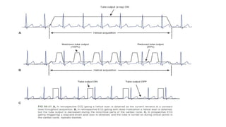
• Proper coronary CTA requires ECG gating to minimize or freeze coronary artery
motion, and several gating options exist (Fig. 58-31).
• In retrospective ECG gating, a volume of data is obtained throughout
• the cardiac cycle using a helical mode
• This technique produces the most complete set of images and permits
assessment of myocardial wall motion and function in addition to coronary
artery evaluation.
16.
• One strategyto decrease such exposure is to use ECG-triggered dose modulation,
• which reduces tube output—and therefore dose—at a designated noncritical
point in the cardiac cycle, generally systole.
• Prospective ECG gating or triggering can be performed in an axial or helical
manner. In the axial mode, sequential scans are performed through the volume of
interest using a step-and-shoot technique at a prespecified point in the cardiac
cycle, usually mid- to late diastole.
• Tube output is turned off for the remainder of the cardiac cycle, leading to dose
reduction on the order of 70% to 80% compared to standard retrospective ECG
gating. In prospective helical gating (high pitched helical acquisition) an entire
volume is scanned within one heart beat, beginning at a preselected time in the
cardiac cycle.
• Major drawbacks of prospective ECG gating are the inability to evaluate cardiac
function (because scanning only occurs during a limited part of the cardiac cycle)
and difficulty with imaging at higher heart rates (>65 bpm).
17.
CONTRAST MEDIUM ADMINISTRATION
•Consideration must be given to the size of the needle and the site of
the injection. Various sized intravenous angiocatheters, such as 18-
gauge, 20-gauge, or 22-gauge, are commonly inserted into a medial
antecubital vein,
• using injections at rates from 3 ml/s to 4 ml/s to 5 ml/s .
• These injection rates may vary among radiology departments.
• the contrast reaches a set value (threshold), the monitoring scan
ends, and the main scan (helical scan) starts automatically to provide
images when contrast flow in the vessels is optimum.
18.
IMAGE RECONSTRUCTION ANDPOSTPROCESSING
• The volume of data acquired from scanning is typically reconstructed
with slice thickness in the range of 0.5 to 0.8 mm using a 50% overlap.
• A field of view of 200 to 250 mm centered on the heart is generally
reconstructed.
• A medium smooth reconstruction kernel is used
• Although axial images are the cornerstone of evaluation of the
coronary arteries, several options exist for postprocessing of the
image data, including multiplanar reformatted (MPR), maximum
intensity projection (MIP), and volumetric images.
CORONARY ARTERY CALCIUMSCORING SCAN
• A noncontrast coronary artery calcium scoring scan can provide an
assessment of risk for major adverse coronary events.
• Coronary CTA allows evaluation of coronary artery stenosis and
remodeling and characterization of coronary plaque
• Coronary artery calcium scoring (CACS) has been well validated as a
marker for cardiovascular risk, providing incremental value in some
instances over information obtained from the population-based
Framingham Risk Score (FRS)
21.
history
• The capabilityof CT to detect coronary artery calcification on CT was initially
described by Guthaner et al. in 1979 on EBCT, and this technique was shown
to be more sensitive than chest radiography or fluoroscopy
• Agatston and his colleagues described the first practical scoring system for
CACS.5 Using 3-mm collimation EBCT, they defined as a calcified focus any
pixel in the coronary arteries with a threshold value of 130 HU or greater,
using a minimum of 1-mm2 area to exclude noise artifact.
• They further stratified scoring based on the density measurement above the
threshold, assigning a score of 1 for 130 to 199 HU, 2 for 200 to 299 HU, 3 for
300 to 399 HU, and 4 for 400 HU or greater.
• The Agatston score is still widely used and is the sum of the score (1-4 above)
on each slice added together for each scan slice
22.
indication
• Coronary Stenosis
•Coronary Plaque(severity, and characteristics of coronary
atherosclerotic plaque, lipid-rich core, a thin fibrous cap, and loss of
integrity of the endothelium, with platelet aggregation)
• Coronary artery aneurysm
• CORONARY ARTERY BYPASS GRAFTS
• CORONARY STENTS
24.
these approaches areless well
validated than the Agatston score.
• Agatston method, scores of 1 to 10 are considered to reflect minimal
coronary artery calcification,
• 11 to 100 mild, 101 to 400 moderate, and greater than 400 severe
calcification.
• An Agatston score of 400 or more indicates a strong possibility
of hemodynamically significant coronary artery stenosis
26.
MYOCARDIAL IMAGING
• Computedtomography myocardial perfusion imaging (CTMPI) provides
functional information in addition to anatomic cardiovascular
assessment via coronary CT angiography (cCTA) and may enhance
diagnostic performance of cardiac CT for detection of hemodynamically
significant coronary artery disease.
27.
Scanning Technique
• Twotechniques can be differentiated:
1) static image of myocardial attenuation at the time of arterial first-
pass perfusion represents a snapshot of the distribution of iodinated
contrast material.
2)Dynamic myocardial perfusion imaging is obtained when myocardial
attenuation is recorded at several consecutive time points.
• The data sample displays the entire heart and can either be acquired
over multiple heartbeats in a certain cardiac phase or within one or
two heartbeats using wide-detector CT technology.
28.
• Volumes ofcontrast medium generally range between 60 and 70 mL.
• The single data sample should be gathered during peak myocardial
contrast material enhancement and therefore requires bolus tracking to
ensure a proper CTMPI acquisition during the contrast enhancement peak.
• Furthermore, if the data are acquired during multiple heartbeats,
myocardial contrast enhancement may vary along the myocardial wall.
• Static CTMPI can also be performed using a dual-energy acquisition
technique
• This technique takes advantage of the improved iodine discrimination
under radiation from different tube voltages and makes quantification of
the myocardial blood pool from iodine concentration possible
29.
• this purposethe two tubes of a dual-source CT system may be operated
simultaneously with different tube voltage settings (100 kV and140 kV),
resulting in a low- and high-photon energy level dataset that can be used
to create an iodine map of the myocardium.
• A different approach to dual-energy static CTMPI is called kV switching and
uses a dual-energy–capable single-source scanner that rapidly switches
tube potential between a low and high tube voltage setting
• “sandwich detector” can be used for dual-energy acquisition, with
superimposition of two detectors in the same gantry, absorbing at
different photon energy levels.
30.
• Dynamic CTMPIallows for assessment of myocardial perfusion using
sequential imaging for the evaluation of changes in contrast attenuation
over time.
• Dynamic CTMPI can be performed either using a stationary table
position or in shuttle mode. With the traditional stationary imaging
technique, myocardial perfusion is recorded at a certain level in cine
mode.
• By use of the shuttle technique, coverage of the whole heart during a
certain cardiac phase is enabled through a backward-forward
alternating position of the table
• dynamic CTMPI allows for absolute quantification of myocardial blood
volume and perfusion, which provides information on myocardial blood
volume and mean transit time for each vascular territory independently
31.
Patient Preparation andImage Acquisition
• patients should be instructed to avoid intake of caffeine and products
containing theophylline, methylxanthine, and dipyridamole because
the vasodilator capacity of pharmacologic stress agents may
consequently be limited during stress imaging
• Furthermore,the use of β-blockers before undergoing the stress
acquisition is considered contraindicated by some because of the
theoretical concern that myocardial ischemia may be masked.
• Nitrates are not recommended before CTMPI, as they may reduce the
diagnostic capabilities for detecting myocardial perfusion defects
32.
• second intravenousaccess is necessary because the infusion of contrast
material and the pharmacologic stressor are simultaneously performed. In
addition to 12-lead electrocardiographic monitoring, continuous blood
pressure surveillance and supervision by a physician certified in Advanced
Cardiovascular Life Support (ACLS) are indicated.
33.
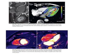
Analysis of CTMPI
•CTMPI reveals decreased myocardial attenuation during the stress phase
only, or if the hypo attenuated area increases significantly, reversible
ischemia can be suspected.
• static CTMPI the coronary arteries are also visualized anatomically, allowing
for detection of diffuse disease. Compared with static CTMPI, the
absolutequantification of blood volume via dynamic CTMPI allows an
accurateassessment of myocardial perfusion without the need for visual
comparison of myocardial segments
35.
references
• COMPUTED TOMOGRAPHYPhysical Principles, Clinical Applications, and Quality Control FOURTH
EDITION (Dr. EUCLID SEERAM, PhD, MSc, BSc, FCAMRT)
• CT AND MRI OF THE WHOLE BODY Sixth Edition (John R. Haaga, MD, FACR, FSIR, FSCBT, FSRS)