SlideShare a Scribd company logo
1 of 21
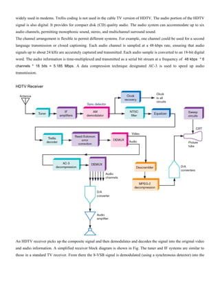
Download to read offline
UNIT II (Television standards and systems)
Interlaced scanning
In a video system a picture is scanned to convert the image to an electrical signal. This scanning is carried
out inside the camera, and at the the receiver end. The form of scanning used in analog television is known
Interlaced scanning. Frame frequency is the number times a complete picture is traced. The rate for PAL
(Phase Alternating Line) TV is 25 frames per second. 25 frames per second is not enough to keep the
human eye from perceiving flicker as a result of a non continues visual presentation. If the frame rate is
increased to 50 per second the flicker would no longer be apparent, but the video signal band would have to
be doubled. Instead of that solution the process on interlaced scanning is used to trick the human eye into
thinking that it is seeing 50 frames per second. The figure 1 gives a simplified view of the process. The odd
set of lines is traced in the first 1/50 Th of a second. The even lines are traced in the second 1/50 Th of a
second. Then the two are interleaved. The field frequency is 50Hz and the frame frequency is 25Hz. This
illusion is enough to convince the eye that 50 pictures per second occur when, infact, there are only 25 full
pictures per second.
1.CCIR/PAL standard video signal has 625 lines/frame
and it repeats @ 25 frames/sec.
2. Each frame is split into 2 fields; - each consisting of
312.5 lines, called odd and even fields. Thus field rate is
50. i.e. CCIR /PAL std has 50 fields/sec rate .
3. 3. Interlacing: The lines of odd-even field lie alternately
. This method of scanning is called interlacing. This
interlaced scanning is used to reduce flicker while
displaying the image on a monitor.
Monochrome picture tube
The receiving antenna intercepts the radiated picture and sound carrier signals and feeds them to the RF
tuner. The receiver is of the heterodyne type and employs two or three stages of intermediate frequency (IF)
amplification. The output from the last IF stage is demodulated to recover the video signal. This signal that
carries the picture information is amplified and coupled to the picture tube which converts the electrical
signal back into picture elements of the same degree of black and white. The picture tube shown in Fig is
very similar to the cathode-ray tube used in an oscilloscope. The glass envelope contains an electrongun
structure that produces a beam of electrons aimed at the fluorescent screen. When the electron beam strikes
the screen, light is emitted. The beam is deflected by a pair of deflecting coils mounted on the neck of the
picture tube in the same way and rate as the beam scans the target in the camera tube. The amplitudes of the
currents in the horizontal and vertical deflecting coils are so adjusted that the entire screen, called raster, gets
illuminated because of the fast rate of scanning.
The video signal is fed to the grid or
cathode of the picture tube. When
the varying signal voltage makes the
control grid less negative, the beam
current is increased, making the spot
of light on the screen brighter. More
negative grid voltage reduces the
brightness. if the grid voltages is
negative enough to cut-off the
electron beam current at the picture tube there will be no light. This state corresponds to black. Thus the
video signal illuminates the fluorescent screen from white to black through various shades of grey depending
on its amplitude at any instant. This corresponds to the brightness changes encountered by the electron beam
of the camera tube while scanning the picture details element by element. The rate at which the spot of light
moves is so fast that the eye is unable to follow it and so a complete picture is seen because of the storage
capability of the human eye.
Colour picture tube
The colour television camera
separates the primary hues from the
televised scene and the colour
picture tube recombines them. The
colour picture tube consists of three
electron guns(red, blue and green
gun) in one picture tube envelope.
The three guns are placed in the
neck of the tube in a triangle(delta). The combinations of these primary colours produce all the other
colours, including white.
The phosphor on the screen or face plate is considerably different from the phosphor of monochrome
picture tubes. Instead of a solid coating of one phosphor on the screen, each of three phosphors is placed in
dots along a horizontal axis in a triangle fashion. The colour tube called the trigun tricolor tube also has a
shadow mask. It ensures that the beams from the three electron guns hit their respective phosphor dots.
The colour tube is scanned in the same way as a
black and white picture tube. If the picture
being received is a black and white picture all
the three guns will be operating. If however, the
picture being televised is in colour, the red gun
will operate for red objects, green for green
objects in the picture and so on. If some other
colour is required, then the proper guns will
operate to mix the basic colours and produce
the desired colour. The quantity of electrons
hitting the phosphor dots is controlled by their respective control grids so as to produce any desired colour.
Luminance signal
The luminance signal can be obtained by adding three primary colour R,G and B. however, the three
voltages contributing the luminance signal must be taken
in different amounts because the human eye responds to
each of the three primaries differently. Calculations show
that then luminance signal associated with whites of the
picture should contain 30% red, 59% green and 11% blue
EY=0.30 ER + 0.59 EG + 0.11 EB
Suppose white stripe is projected on colour camera
tubes, the diachronic mirrors will split light from the
white stripe into three colour components R,G and B. the
gain of the video amplifiers can then be adjusted so that
their output voltage is the same i.e.: ER=EG=EB
This is the relative sensitivity of a three camera tube. The
luminance signal essential to operation of a black and white TV, is produced by means of a matrix. The
circuit of simple matrix composed of four resistor(three voltage dividers) is shown in the figure. If the values
of R1,R2 and R3 are chosen to be sufficiently high in comparison with Rout, the voltage dividers are mutually
isolated so that the following voltages are developed across the resistor Rout
ERout=ER(Rout/R1) ;EGout=EG(Rout/R2) ;EBout=EB(Rout/R3) ;
By setting the scale factors Rout/R1=0.30, Rout/R2 =0.59 and Rout/R3=0.11 the following luminance signal will
be secured at the matrix output
EY=ERout + EGout + EBout
EY=0.30 ER + 0.59 EG + 0.11 EB
Chrominance signal
The generation of chrominance signal
involves the separation of the
luminance signal, EY from the natural
colour signals, ER, EG and EB. The
natural colour signals are developed
across resistors R1, R2 and R3
respectively is simultaneously fed to
the adders in the stages 2, 3 and 4.
When a white scene is being televised,
the three pick-up tubes will extract the
three primary colours from the white
light and develop corresponding
voltages across r1,r2 and R3. Since light falls on all the three pick-up tubes with the same intensity, these
three voltages would be equal
ER + EG + EB=1V
Adder stage 1 will produce an output of 0.30 ER + 0.59 EG + 0.11 EB . the sum of these voltages is the
voltage Ey corresponding to white light. As such, the output from adder stage 1, will be EY=1v. The output
is routed through an low pass filter(LPF) to an amolifier stage which is a common emitter amplifier, so that
at its output signal is –EY, whose value in this example will be -1V.
The (–EY) signal is applied simultaneously to stage 2, 3 and 4. To these stages the full voltages ER, EG and
EB are also applied. In the case of white light each of these three voltages are each equal to 1v. Thus each of
the 2,3 and 4 stages has two inputs -EY=-1V and ER + EG + EB=1v
Obviously the output of each adder stages 2,3 and 4 will be zero. These four outputs are brought out from
terminal 1 to 4 and routed to the TV transmitter after due processing. This, then , is the process of television
a white scene. The luminance signal is available at terminal 1 for transmission and no signal is available at
terminal 2,3 and 4.
Television remote control
The figure shows the television remote control transmitter uses two separate oscillators. One of the
oscillator generates a carrier wave and the other, a modulating signal. By a slight variation in the tuning
circuit, the carrier oscillator can produce four or more different frequencies, example 35.43Khz,
38.29khz,41.14 khz and 4401khz.similarly, the other oscillator, for generating modulating signal, can
produce 148hz,193hz,244hz or 333hz. A modulating signal amplitude modulates any one of the four carrier
frequencies depending upon the remote operation required. In this way, one would able to select any of the
16 frequency combinations for transmitter by 4x4 matrix of push buttons switches. Each frequency
combination represents a specific instruction.
In the ultrasonic receiver, a narrow band
pass filter(F1) allows only those signals
whose frequencies lie within 35khz to 45
khz range. All such signals are then
applied to four more narrow band pass
filter(F2 to F5), only one of which will
allow the frequency, already accepted by
F1, to pass. Thus these filters act as
signal sorts ensuring that the desired
signal is always routed to its correct
terminals on the matrix decoder.
On leaving F2-F5, the desired signal is rectified by one of the four detectors D1-D4. It is then applied
without high pass filtering to
any one of the detector
integrators D5 to D8, and to
the signal combiner unit.
Since a detector integrator
can produce an output only if
it receives the correct input, a
rectified signal at the input of
a particular detector-
integrator produces a DC
signal at its output. This
signal is applied to the
appropriate terminal of the
matrix decoder as a carrier
identifier. It is now necessary to determine which of the four possible modulating frequencies is being
applied to the identified carrier.
The signal combiner accepts any of the rectified, but unfiltered, modulated carrier derived from detectors
D1-D4 and feeds the one it receives simultaneously to the four narrow band pass filters F6-F9. Only one of
these filters will allow the modulating signal of the received carrier to pass, and so only on of the four
possible modulating signal will be allowed to reach the detector integrator, D9-D12.
Theses operate in the same way as D5 – D8, producing a their output dc signals corresponding to one
particular modulating frequency. These DC signal are applied to the appropriate terminals of the matrix
decoder as modulation identifiers, from these two identifiers the matrix decode produces a signal at one of its
16 output terminals.
COMPONENTS OF A TV SYSTEM:
The fundamental aim of a television system is to extend the sense of sight beyond its natural limits,
along with the sound associated with the scene being televised. Essentially then, a TV system is an extension
of the science of radio communication with the additional complexity that besides sound the picture details
are also to be transmitted. In most television systems, as also in the C.C.I.R. 625 line monochrome system
adopted by India, the picture signal is amplitude modulated and sound signal frequency modulated before
transmission. The carrier frequencies are suitably spaced and the modulated outputs radiated through a
common antenna. Thus each broadcasting station can have its own carrier frequency and the receiver can
then be tuned to select any desired station. Figure shows a simplified block representation of a TV
transmitter and receiver.
PICTURE TRANSMISSION:
The picture information is optical in character and may be thought of as an assemblage of a large
number of bright and dark areas representing picture details. These elementary areas into which the picture
details may be broken up are known as ‗picture elements‘, which when viewed together, represent the visual
information of the scene. Thus the problem of picture transmission is fundamentally much more complex,
because, at any instant there are almost an infinite number of pieces of information, existing simultaneously,
each representing the level of brightness of the scene to the reproduced. In other words the information is a
function of two variables, time and space. Ideally then, it would need an infinite number of channels to
transmit optical information corresponding to all the picture elements simultaneously. Presently the practical
difficulties of transmitting all the information simultaneously and decoding it at the receiving end seem
insurmountable and so a method known as scanning is used instead. Here the conversion of optical
information to electrical form and its transmission are carried out element by element, one at a time and in a
sequential manner to cover the entire scene which is to be televised. Scanning of the elements is done at a
very fast rate and this process is repeated a large number of times per second to create an illusion of
simultaneous pick-up and transmission of picture details.
A TV camera, the heart of which is a camera tube, is used to convert the optical information into a
corresponding electrical signal, the amplitude of which varies in accordance with the variations of
brightness. Fig. shows very elementary details of one type of camera tube to illustrate this principle. An
optical image of the scene to be transmitted is focused by a lens assembly on the rectangular glass face-plate
of the camera tube. The inner
Basic monochrome television transmitter
Basic monochrome television receiver.
Simplified block diagram of a monochrome television broadcasting system.
side of the glass face-plate has a transparent conductive coating on which is laid a very thin layer of
photoconductive material. The photolayer has a very high resistance when no light falls on it, but decreases
depending on the intensity of light falling on it. Thus depending on the light intensity variations in the
focused optical image, the conductivity of each element of the photolayer changes accordingly. An electron
beam is used to pick-up the picture information now available on the target plate in terms of varying
resistance at each point. The beam is formed by an electron gun in the TV camera tube. On its way to the
inner side of the glass faceplate it is deflected by a pair of deflecting coils mounted on the glass envelope and
kept mutually perpendicular to each other to achieve scanning of the entire target area. Scanning is done in
the same way as one reads a written page to cover all the words in one line and all the lines on the page. To
achieve this the deflecting coils are fed separately from two sweep oscillators which continuously generate
saw-tooth waveforms, each operating at a different desired frequency. The magnetic deflection caused by the
current in one coil gives horizontal motion to the beam from left to right at a uniform rate and then brings it
quickly to the left side to commence the trace of next line. The other coil is used to deflect the beam from
top to bottom at a uniform rate and for its quick retrace back to the top of the plate to start this process all
over again. Two simultaneous motions are thus given to the beam, one from left to right across the target
plate and the other from top to bottom thereby covering the entire area on which the electrical image of the
picture is available. As the beam moves from element to element, it encounters a different resistance across
the target-plate, depending on the resistance of the photoconductive coating. The result is a flow of current
which varies in magnitude as the elements are scanned. This current passes through a load resistance RL,
connected to the conductive coating on one side and to a dc supply source on the other. Depending on the
magnitude of the current a varying voltage appears across the resistance RL and this corresponds
to the optical information of the picture.
NTSC:
NTSC, named for the National Television System Committee, is the analog television system that is used in
most of North America, most of South America(except Brazil, Argentina, Uruguay, and French
Guiana), Burma, South Korea,Taiwan, Japan, the Philippines, and some Pacific island nations and territories.
Most countries using the NTSC standard, as well as those using other analog television standards, are
switching to newer digital television standards, of which at least four different ones are in use around the
world. North America, parts of Central America, and South Korea are adopting the ATSC standards, while
other countries are adopting or have adopted other standards.
The first NTSC standard was developed in 1941 and had no provision for color television. In 1953 a second
modified version of the NTSC standard was adopted, which allowed color television broadcasting
compatible with the existing stock of black-and-white receivers. NTSC was the first widely adopted
broadcast color system. After nearly 70 years of use, the vast majority of over-the-air NTSC transmissions in
the United States were replaced with digital ATSC on June 12, 2009 and August 31, 2011 in Canada and
most other NTSC markets. Despite the shift to digital broadcasting, standard definition television in these
countries continues to follow the NTSC standard in terms of frame rate and number of lines of resolution. In
the United States a small number of short-range local and TV relay stations continue to broadcast NTSC, as
the FCC allows. NTSC baseband video signals are also still often used in video playback and in CCTV and
surveillance video systems.
PAL:
Short for Phase Alternating Line, the dominant television standard in Europe. The United States uses a
different standard, NTSC. Whereas NTSC delivers 525 lines of resolution at 60 half-frames per second, PAL
delivers 625 lines at 50 half-frames per second. Many video adapters that enable computer monitors to be
used as television screens support both NTSC and PAL signals.
NTSC receivers have a tint control to perform colour correction manually. If this is not adjusted correctly,
the colours may be faulty. The PAL standard automatically cancels hue errors by phase reversal, so a tint
control is unnecessary. Chrominance phase errors in the PAL system are cancelled out using a 1H delay
line resulting in lower saturation, which is much less noticeable to the eye than NTSC hue errors.
However, the alternation of colour information — Hanover bars — can lead to picture grain on pictures with
extreme phase errors even in PAL systems, if decoder circuits are misaligned or use the simplified decoders
of early designs (typically to overcome royalty restrictions). In most cases such extreme phase shifts do not
occur. This effect will usually be observed when the transmission path is poor, typically in built up areas or
where the terrain is unfavourable. The effect is more noticeable on UHF than VHF signals as VHF signals
tend to be more robust.
In the early 1970s some Japanese set manufacturers developed decoding systems to avoid paying royalties
to Telefunken. The Telefunken license covered any decoding method that relied on the alternating subcarrier
phase to reduce phase errors. This included very basic PAL decoders that relied on the human eye to average
out the odd/even line phase errors. One solution was to use a 1Hdelay line to allow decoding of only the odd
or even lines. For example, the chrominance on odd lines would be switched directly through to the decoder
and also be stored in the delay line. Then, on even lines, the stored odd line would be decoded again. This
method effectively converted PAL to NTSC. Such systems suffered hue errors and other problems inherent
in NTSC and required the addition of a manual hue control.
PAL and NTSC have slightly divergent colour spaces, but the colour decoder differences here are ignored.
SECAM:
SECAM is an earlier attempt at compatible colour television which also tries to resolve the NTSC
hue problem. It does so by applying a different method to colour transmission, namely alternate transmission
of the U and V vectors and frequency modulation, while PAL attempts to improve on the NTSC method.
SECAM transmissions are more robust over longer distances than NTSC or PAL. However, owing to their
FM nature, the colour signal remains present, although at reduced amplitude, even in monochrome portions
of the image, thus being subject to stronger cross colour. Like PAL, a SECAM receiver needs a delay line.
COMPOSITE VIDEO SIGNAL:
• Camera signal - corresponding to the desired picture information
• Blanking pulses – to make the retrace invisible
• Synchronizing pulses – to synchronize the transmitter and receiver scanning
-horizontal sync pulse
-vertical sync pulse
-their amplitudes are kept same
-but their duration are different
-needed consecutively and not simultaneously with the picture signal – so sent on a
time division basis
LCD TV
A Liquid crystal display is a passive device, which means it doesn‘t produce any light to display characters,
images, video and animations. But it simply alters the light travelling through it. The internal construction of LCD
describes how the light altered when it passes through it in order to produce any characters, images, etc.
Consider a single
pixel area in LCD, in
which there are two
polarization filters
oriented at 90 degree
angle to each other as
shown in figure 1.1. These
filters are used to polarize
the unpolarized light. The
first filter (Vertical
polarized filter in figure
1.1) polarizes the light
with one polarization
plane (Vertical). When the
vertically polarized light
passes through the second
filter (Horizontal polarized
filter) no light output will
produce.
Figure 1.1 Orientation of two polarization filters in LCD
The vertically polarized light should rotate 90 degrees in order to pass through the horizontal polarized light.
This can be achieving by embedding liquid crystal layer between two polarization filters. The liquid crystal layer
consists of rod shaped tiny molecules and ordering of these molecules creates directional orientation property. These
molecules in the liquid crystal are twisted 90 degrees as shown in the figure 1.2. The vertically polarized light passes
through rotation of the molecules and twisted to 90 degrees. When the orientation of light matches with the outer
polarization filter light will pass it and brightens the screen.
Figure 1.2 Liquid Crystal molecules orientation.
If the Liquid crystal molecules are twisted 90 degrees more precisely, then more light will pass through it.
Two glass transparent electrodes are aligned front and back of the liquid crystal in order to change the orientation of
the crystal molecules by applying voltage between them as shown in figure 1.3 and figure 1.4. If there is no voltage
applied between the electrodes, the orientation of molecules will remain twist at 90 degrees and the light passes
through the outer polarization filter thus pixel appears as complete white. If the voltage is applied large enough the
molecules in the liquid crystal layer changes its orientation (untwist) so that light orientation also changes and then
blocked by the outer polarization filter thus the pixel appears black. In this way, black and white images or characters
are produced. By arranging small pixels together as a matrix will produce on which it is possible to show different
sizes of images and characters. By controlling the voltage applied between liquid crystal layers in each pixel, light can
be allowed to pass through outer polarization filter in various amounts, so that it can possible to produce different gray
levels on the LCD screen.
Generally the electrodes is made up of Indium Tin Oxide (ITO) which is transparent material, hence it is
simply called glass electrodes plates. LCD display is also ―twisted nematic LCD‖ because of twist and untwist of
molecules in liquid crystal layer.
Figure 1.3
In order to produce color images a color filter is placed in front of the outer polarization plate as shown in
figure1.5. The red, green and blue are the three standard colors filters are placed for every three pixels to produce
different color images by varying the intensity of each color.
Figure 1.4
LED (Light Emitting Diodes) TVs are basically LCDs only. The difference is that the lamp behind
the screen that was used to illuminate the fluorescent display in LCD is replaced by small LEDs. The
working of the TV remains the same, but due to the use of LEDs the screen is much slimmer in size, power
efficient and can yield a true black effect to a much greater extent.
DTH (Direct to home) or DBS(Direct broadcast satellite)
A block diagram of a typical DBS digital receiver is shown in Fig. The receiver subsystem begins
with the antenna and its low-noise block converter. The horn antenna picks up the Ku band signal and
translates the entire 500-MHz band used by the signal down to the 950- to 1450-MHz range. The RF signal
from the antenna is sent by coaxial cable to the receiver.
The received signal is passed through another mixer with a variable-frequency local oscillator to
provide channel selection. The digital signal at the second IF is then demodulated to recover the originally
transmitted digital signal, which is passed through a forward error correction (FEC) circuit. This circuit is
designed to detect bit errors in the transmission and to correct them on the fly. Any bits lost or obscured by
noise during the transmission process are usually caught and corrected to ensure a near-perfect digital signal.
The resulting error-corrected signals are then sent to the audio and video decompression circuits. Then they
are stored in random access memory (RAM), after which the signal is decoded to separate it into both the
video and the audio portions. The DBS TV system uses digital compression-decompression standards
referred to as MPEG2 (MPEG means Moving Picture Experts Group, which is a standards organization that
establishes technical standards for movies and video). MPEG2 is a compression method for video that
achieves a compression of about 50 to 1 in data rate. Finally, the signals are sent to D/A converters that
modulate the RF modulator which sends the signals to the TV set antenna terminals.
HDTV (High definition TV)
Transmission Concepts
HDTV Transmitter. Figure shows the block diagram of an HDTV transmitter. The video from the camera consists of
the R, G, and B signals that are converted to the luminance and chrominance signals. These are digitized by A/D
converters. The luminance sampling rate is 14.3 MHz, and the chroma sampling rate is 7.15 MHz. The resulting
signals are serialized and sent to a data compressor. The purpose of this device is to reduce the number of bits needed
to represent the video data and therefore permit higher transmission rates in a limited-bandwidth channel. MPEG-2 is
the data compression method used in HDTV. The MPEG-2 data compressor processes the data according to an
algorithm that effectively reduces any redundancy in the video signal. The MPEG-2 encoder captures and compares
successive frames of video and compares them to detect the redundancy so that only differences between successive
frames are transmitted. The signal is next sent to a data randomizer. The randomizer scrambles or randomizes the
signal. This is done to ensure that random data is transmitted even when no video is present or when the video is a
constant value for many scan lines. This permits clock recovery at the receiver.
Next the random serial signal is passed through a Reed-Solomon (RS) error detection and correction circuit.
This circuit adds extra bits to the data stream so that transmission errors can be detected at the receiver and corrected.
This ensures high reliability in signal transmission even under severe noise conditions. In HDTV, the RS encoder adds
20 parity bytes per block of data that can provide correction for up to 10 byte errors per block. The signal is next fed to
a trellis encoder. This circuit further modifies the data to permit error correction at the receiver. Trellis encoding is
widely used in modems. Trellis coding is not used in the cable TV version of HDTV. The audio portion of the HDTV
signal is also digital. It provides for compact disk (CD) quality audio. The audio system can accommodate up to six
audio channels, permitting monophonic sound, stereo, and multichannel surround sound.
The channel arrangement is flexible to permit different systems. For example, one channel could be used for a second
language transmission or closed captioning. Each audio channel is sampled at a 48-kbps rate, ensuring that audio
signals up to about 24 kHz are accurately captured and transmitted. Each audio sample is converted to an 18-bit digital
word. The audio information is time-multiplexed and transmitted as a serial bit stream at a frequency of 48 kbps * 6
channels * 18 bits = 5.185 Mbps. A data compression technique designated AC-3 is used to speed up audio
transmission.
HDTV Receiver
An HDTV receiver picks up the composite signal and then demodulates and decodes the signal into the original video
and audio information. A simplified receiver block diagram is shown in Fig. The tuner and IF systems are similar to
those in a standard TV receiver. From there the 8-VSB signal is demodulated (using a synchronous detector) into the
original bit stream. A balanced modulator is used along with a carrier signal that is phase-locked to the pilot carrier to
ensure accurate demodulation.
A clock recovery circuit regenerates the clock signal that times all the remaining digital operations.The signal
then passes through an NTSC filter that is designed to filter out any one channel or adjacent channel interference from
standard TV stations. The signal is also passed through an equalizer circuit that adjusts the signal to correct for
amplitude and phase variations encountered during transmission. The signals are demultiplexed into the video and
audio bit streams. Next, the trellis decoder and RS decoder ensure that any received errors caused by noise are
corrected.
The signal is descrambled and decompressed. The video signal is then converted back to the digital signals that will
drive the D/A converters that, in turn, drive the red, green, and blue electron guns in the CRT. The audio signal is also
de multiplexed and fed to AC-3 decoders. The resulting digital signals are fed to D/A converters that create the
analog audio for each of the six audio channels.
Camera tubes
TV Camera Tubes: Camera is the first and basic equipment in a TV. The input to a camera is the light from
the picture or scene to be televised and output obtained from camera is the electrical pulses corresponding to
the information contained in picture.
The image-orthicon, vidicon and plumbicon are some important electronic scan camera tubes which find
wide applications these days.
1. Image Orthicon:
It is a sensitive tube and is capable of handling a wide range of light values and contrast. In a single
envelope, it includes three sections:
(a). Image Section: This section includes:
1. a photo sensitive surface, called photo cathode, operated at a very large negative potential.
2. a target plate which is a thin plate of glass of low resistivity. Thickness is less than 0.0002 in.
3. a screen located very close to target plate and has about 500,000 openings per square inch.
When the optical image is focused on the photo cathode, photoelectrons, in proportion to the amount of light
impinging, are emitted. Most of the photoelectrons pass through the screen and hit the target plate.
As the photoelectrons are accelerated to several hundred electron volts, they liberate several secondary
electrons from the target plate surface, and are then collected by the nearby-screen which is at a small
positive potential. The emission of secondary electrons from target plate leaves a distribution of positive
charge on its surface. The low resistivity of target plate resists the lateral charge flow on its surface and thus
the image charge pattern, formed on the plate, is truly restored as such. Since the plate is thin, this charge
pattern also appears on the other side (away from screen) of the plate.
(b). Scanning Section: The otherside of the pattern is now scanned by a beam of low velocity electrons
generated by an electron gun. The beam is deflected on the plate in vertical and horizontal directions and
enables the electron beam to scan the whole plate. This beam gives up the number of electrons required to
neutralize the positive charge at that point and thus the returning electron beam varies in magnitude in
accordance with the brightness variation of the image. It should be noted here that since the target portion
affected by the white portion of the image will be positively charged and hence the electron beam has to give
up large number of electrons to neutralize the positive charge at that point, i.e., the intensity of returning
electron beam is much reduced and the video signal developed across the output resistor for this part will be
small. It, therefore, concludes that the brightest part of image are transmitted as the signals of low amplitude
which is very advantageous in avoiding the effect of strong noise at the receiver.
(c). Electron Multiplier Section: An electron multiplier is located within the pick-up tube for amplifying the
electron density variation in the returning beam.
Merits and Demerits:
1.It has high Sensitivity
2. The S/N ratio is better and its typical value is 30 dB.
3. It‘s spectral response is close to eyes.
4. The ratio of signal current to illumination os gamma and it varies from unity at low light to 0.5 at high
light levels.
5. It produces no lag.
6. Size of image orthicon is bulky in nature.
7. It‘s operation is elaborate.
8. It is very costly camera tube and life time of this camera tube is nearly 1500 to 6000 hrs.
2. Vidicon:
This camera tube based on the photo conductive properties of semiconductors i.e., decrease in resistance
with the amount of incident light. The tube is shown in figure. It consists of
(a). Signal Plate: Which is a conducting metallic film very thin so as to be transparent. The side of this film
facing cathode is coated with a very thin layer of photoconductive material (amorphousselenium). This side
is scanned by electron beam. The optical image is focused on the other side of this film.
(b).Scanning System: The electron beam for scanning is formed by the combination of cathode, control grid-
1, accelerating grid-2 and anode grid-3. The focusing coil produces an axial field which focuses the beam on
the film. Vertical and horizontal deflection of the beam, so as to the scan the whole film, is accomplished by
passing saw-tooth current waves through deflecting coils which thus produce transverse horizontal and
vertical magnetic fields respectively. The alignment coils are for initial adjustment of the direction of
electron beam.
Operation: When the scanning beam passes over the photo conductive material of the signal plate, it deposits
electrons so that the potential of this side of plate is reduced to that of the cathode. But the otherside of the
film (plate) is still at its original potential. Consequently a potential difference across a given pointon the
photoconductive material is created. It is approximately 30 V. Before the next scanning (which may be done
after an interval of 1/50 or 1/25 sec.) the charge leaks through photoconductive material at a rate determined
by the conductivity of the material which, in turn depends upon the amount of incident light.
White portions of the object will project more light on the film and make it more conductive. This charge
leaked to photoconductive side of the film will vary according to illumination of the object. As a result,
potential at every point on the photoconductive side will vary. Now the electron beam again starts scanning
the photoconductive side of the film but this time the charge deposited by the beam in order to reduce its
potential towards zero (cathode potential) will vary with time. Therefore current through RL (and hence the
output voltage) will follow the changes in potential difference between two surfaces of the film and hence
follows the variations of light intensity of successive points in the optical image.
Advantages:
1. Low cost.
2. Simple Adjustment.
3. Sensitivity is large.
4. Resolution of the order of 350 lines can be achieved under practical conditions.
Disadvantages:
1. Owing to the fact that the resistance of the photoconductive film does not change instantaneously
with change of light intensity, different levels of light intensity are adjusted with slight time slag.
2. The response characteristic is non-linear.
3. Plumbicon:
The construction of a plumbicon camera tube is similar to that of a standard vidicon except for the target
material. The plumbicon has a new type of photo-conductive target, i.e., lead oxide of the form PbO. The
figure below shows the constructional features of a plumbicon camera.
Operation: The operation of a plumbicon camera tube can be best explained from the diagram. Initially,
when there is no light input, the PIN diode is reverse biased due to a positive potential appearing on
SnO2 coating (n-type) and p-type stabilized at a potential slightly below the cathode due to negatively
charged scanning beam. This results in a very small output current which is almost negligible. This is the
greatest advantage of a plumbicon camera tube especially when used with color systems. The photo
electronic conversion is almost similar to that of a standard vidicon except for the method of discharging
each storage element. In standard vidicon each element acted as a leaky capacitor with leakage resistance
decreasing with more light. Here when light falls on the target, the diode becomes forward biased upon the
extent depending upon light intensity. The forward bias on each diode results from the photo excitation of
the pure PbO and doped PbO junction. Thus the target behaves as a capacitor in series with PIN diode.
Merits and Demerits:
1. In plumbicons, the uniluminated or the dark current is negligible and also it is temperature independent.
2. It has got high sensitivity and a high signal to noise ratio.
3. Resolution is good but not as good as that of a vidicon.
4. Operational gamma is unity.
5. It is compact and exhibits simplicity of operation.
6. It is free of spurious signals.
7. Susceptibility to damage by over loads is not as severe as it is in vidicons.
8. There are some forms of PbO which have spectral limitations.

More Related Content

What's hot

Unit iv wcn main
Unit iv wcn mainUnit iv wcn main
Unit iv wcn mainvilasini rvr
 
Software PLL for PLI synchronization, design, modeling and simulation , sozopol
Software PLL for PLI synchronization, design, modeling and simulation , sozopolSoftware PLL for PLI synchronization, design, modeling and simulation , sozopol
Software PLL for PLI synchronization, design, modeling and simulation , sozopoldpdobrev
 
Chapter2 cont
Chapter2 contChapter2 cont
Chapter2 contmkazree
 
Comm lab manual_final-1
Comm lab manual_final-1Comm lab manual_final-1
Comm lab manual_final-1Abhishek Bansal
 
Ac lab final_report
Ac lab final_reportAc lab final_report
Ac lab final_reportGeorge Cibi
 
Introduction to equalization
Introduction to equalizationIntroduction to equalization
Introduction to equalizationHarshit Srivastava
 
Communicationlabmanual
CommunicationlabmanualCommunicationlabmanual
Communicationlabmanualjkanth26
 
Equalization
EqualizationEqualization
Equalization@zenafaris91
 
NTSC Software Decoding Presentation
NTSC Software Decoding PresentationNTSC Software Decoding Presentation
NTSC Software Decoding PresentationPrateek Dayal
 
Ads harmonic balance
Ads harmonic balanceAds harmonic balance
Ads harmonic balanceSaravana Selvan
 
Adaptive equalization
Adaptive equalizationAdaptive equalization
Adaptive equalizationOladapo Abiodun
 
Lecture Notes: EEEC6440315 Communication Systems - Digital Modulation
Lecture Notes:  EEEC6440315 Communication Systems - Digital ModulationLecture Notes:  EEEC6440315 Communication Systems - Digital Modulation
Lecture Notes: EEEC6440315 Communication Systems - Digital ModulationAIMST University
 
Advanced communication lab manual
Advanced communication lab manual Advanced communication lab manual
Advanced communication lab manual AJAL A J
 
Equalization
EqualizationEqualization
Equalizationbhabendu
 
linear equalizer and turbo equalizer
linear equalizer and turbo equalizerlinear equalizer and turbo equalizer
linear equalizer and turbo equalizerDivya_mtech
 
Eecb351 exp 8 ask fsk
Eecb351 exp 8 ask fskEecb351 exp 8 ask fsk
Eecb351 exp 8 ask fskZufayri Chan
 
Optical recording system
Optical recording systemOptical recording system
Optical recording systemTamilarasan N
 
CHANNEL EQUALIZATION by NAVEEN TOKAS
CHANNEL EQUALIZATION by NAVEEN TOKASCHANNEL EQUALIZATION by NAVEEN TOKAS
CHANNEL EQUALIZATION by NAVEEN TOKASNAVEEN TOKAS
 

What's hot (20)

Unit iv wcn main
Unit iv wcn mainUnit iv wcn main
Unit iv wcn main
 
Software PLL for PLI synchronization, design, modeling and simulation , sozopol
Software PLL for PLI synchronization, design, modeling and simulation , sozopolSoftware PLL for PLI synchronization, design, modeling and simulation , sozopol
Software PLL for PLI synchronization, design, modeling and simulation , sozopol
 
Chapter2 cont
Chapter2 contChapter2 cont
Chapter2 cont
 
Comm lab manual_final-1
Comm lab manual_final-1Comm lab manual_final-1
Comm lab manual_final-1
 
Ac lab final_report
Ac lab final_reportAc lab final_report
Ac lab final_report
 
Introduction to equalization
Introduction to equalizationIntroduction to equalization
Introduction to equalization
 
Communicationlabmanual
CommunicationlabmanualCommunicationlabmanual
Communicationlabmanual
 
Equalization
EqualizationEqualization
Equalization
 
Analog comm lab manual
Analog comm lab manualAnalog comm lab manual
Analog comm lab manual
 
NTSC Software Decoding Presentation
NTSC Software Decoding PresentationNTSC Software Decoding Presentation
NTSC Software Decoding Presentation
 
Ads harmonic balance
Ads harmonic balanceAds harmonic balance
Ads harmonic balance
 
Adc assignment final
Adc assignment finalAdc assignment final
Adc assignment final
 
Adaptive equalization
Adaptive equalizationAdaptive equalization
Adaptive equalization
 
Lecture Notes: EEEC6440315 Communication Systems - Digital Modulation
Lecture Notes:  EEEC6440315 Communication Systems - Digital ModulationLecture Notes:  EEEC6440315 Communication Systems - Digital Modulation
Lecture Notes: EEEC6440315 Communication Systems - Digital Modulation
 
Advanced communication lab manual
Advanced communication lab manual Advanced communication lab manual
Advanced communication lab manual
 
Equalization
EqualizationEqualization
Equalization
 
linear equalizer and turbo equalizer
linear equalizer and turbo equalizerlinear equalizer and turbo equalizer
linear equalizer and turbo equalizer
 
Eecb351 exp 8 ask fsk
Eecb351 exp 8 ask fskEecb351 exp 8 ask fsk
Eecb351 exp 8 ask fsk
 
Optical recording system
Optical recording systemOptical recording system
Optical recording system
 
CHANNEL EQUALIZATION by NAVEEN TOKAS
CHANNEL EQUALIZATION by NAVEEN TOKASCHANNEL EQUALIZATION by NAVEEN TOKAS
CHANNEL EQUALIZATION by NAVEEN TOKAS
 

Similar to Television standards and systems

TRAINING REPORT
TRAINING REPORTTRAINING REPORT
TRAINING REPORTGheethu Joy
 
Doordarshan Lucknow Summer Training Report
Doordarshan Lucknow Summer Training ReportDoordarshan Lucknow Summer Training Report
Doordarshan Lucknow Summer Training ReportNIMISHADWIVEDI4
 
Images
ImagesImages
Imagesadil raja
 
chapter-03.pptx TV transmission Balck and White Color
chapter-03.pptx  TV transmission Balck and White Colorchapter-03.pptx  TV transmission Balck and White Color
chapter-03.pptx TV transmission Balck and White ColorSANGRAMJADHAV49
 
chapter-03cel.pptx deals with TV fundamentals
chapter-03cel.pptx deals with TV fundamentalschapter-03cel.pptx deals with TV fundamentals
chapter-03cel.pptx deals with TV fundamentalsJatin Patil
 
CRO-SARAVANA SELVI.pdf which is visualise the electrical signal into waveform
CRO-SARAVANA SELVI.pdf which is visualise the electrical signal into waveformCRO-SARAVANA SELVI.pdf which is visualise the electrical signal into waveform
CRO-SARAVANA SELVI.pdf which is visualise the electrical signal into waveformsivanandagouda57
 
CRO is the instrument that which visualise tha electrical signal into waveform
CRO is the instrument that which visualise tha electrical signal into waveformCRO is the instrument that which visualise tha electrical signal into waveform
CRO is the instrument that which visualise tha electrical signal into waveformsivanandagouda57
 
Analog TV set by Amjad Abdulsatar.pptx
Analog TV set by Amjad Abdulsatar.pptxAnalog TV set by Amjad Abdulsatar.pptx
Analog TV set by Amjad Abdulsatar.pptxAmjadAbdulsatarMasee
 
Wireless/Wired Automatic Switched Plasma Tweeter & Speaker System
Wireless/Wired Automatic Switched Plasma Tweeter & Speaker SystemWireless/Wired Automatic Switched Plasma Tweeter & Speaker System
Wireless/Wired Automatic Switched Plasma Tweeter & Speaker SystemIOSRJECE
 
CG03 Random Raster Scan displays and Color CRTs.ppsx
CG03 Random Raster Scan displays and Color CRTs.ppsxCG03 Random Raster Scan displays and Color CRTs.ppsx
CG03 Random Raster Scan displays and Color CRTs.ppsxjyoti_lakhani
 
Ddk patna soft copy
Ddk patna soft copyDdk patna soft copy
Ddk patna soft copyNIRAJ KUMAR
 
Cathode Ray Oscilloscope
Cathode Ray OscilloscopeCathode Ray Oscilloscope
Cathode Ray OscilloscopeEkambareshToulam
 
Module-V-Wave-Analyzers-G.Anitha.ppt
Module-V-Wave-Analyzers-G.Anitha.pptModule-V-Wave-Analyzers-G.Anitha.ppt
Module-V-Wave-Analyzers-G.Anitha.pptMANIMEGALAIMECE
 
Cro (emmi) (1)
Cro (emmi) (1)Cro (emmi) (1)
Cro (emmi) (1)Ravi Anand
 
CRO and FG.ppt
CRO and FG.pptCRO and FG.ppt
CRO and FG.pptAnaniahDurai1
 
Broadcasting and video systems
Broadcasting and video systemsBroadcasting and video systems
Broadcasting and video systemsMohammad Bappy
 
Presentaion on dual trace oscilloscope
Presentaion on dual trace oscilloscopePresentaion on dual trace oscilloscope
Presentaion on dual trace oscilloscopeAliya Sahir
 

Similar to Television standards and systems (20)

TRAINING REPORT
TRAINING REPORTTRAINING REPORT
TRAINING REPORT
 
3Ganar_unit-1ttelevision3.ppt
3Ganar_unit-1ttelevision3.ppt3Ganar_unit-1ttelevision3.ppt
3Ganar_unit-1ttelevision3.ppt
 
Doordarshan Lucknow Summer Training Report
Doordarshan Lucknow Summer Training ReportDoordarshan Lucknow Summer Training Report
Doordarshan Lucknow Summer Training Report
 
Images
ImagesImages
Images
 
Doordarshan Lucknow Summer training report
Doordarshan Lucknow Summer training reportDoordarshan Lucknow Summer training report
Doordarshan Lucknow Summer training report
 
chapter-03.pptx TV transmission Balck and White Color
chapter-03.pptx  TV transmission Balck and White Colorchapter-03.pptx  TV transmission Balck and White Color
chapter-03.pptx TV transmission Balck and White Color
 
chapter-03cel.pptx deals with TV fundamentals
chapter-03cel.pptx deals with TV fundamentalschapter-03cel.pptx deals with TV fundamentals
chapter-03cel.pptx deals with TV fundamentals
 
CRO-SARAVANA SELVI.pdf which is visualise the electrical signal into waveform
CRO-SARAVANA SELVI.pdf which is visualise the electrical signal into waveformCRO-SARAVANA SELVI.pdf which is visualise the electrical signal into waveform
CRO-SARAVANA SELVI.pdf which is visualise the electrical signal into waveform
 
CRO is the instrument that which visualise tha electrical signal into waveform
CRO is the instrument that which visualise tha electrical signal into waveformCRO is the instrument that which visualise tha electrical signal into waveform
CRO is the instrument that which visualise tha electrical signal into waveform
 
Analog TV set by Amjad Abdulsatar.pptx
Analog TV set by Amjad Abdulsatar.pptxAnalog TV set by Amjad Abdulsatar.pptx
Analog TV set by Amjad Abdulsatar.pptx
 
Wireless/Wired Automatic Switched Plasma Tweeter & Speaker System
Wireless/Wired Automatic Switched Plasma Tweeter & Speaker SystemWireless/Wired Automatic Switched Plasma Tweeter & Speaker System
Wireless/Wired Automatic Switched Plasma Tweeter & Speaker System
 
CG03 Random Raster Scan displays and Color CRTs.ppsx
CG03 Random Raster Scan displays and Color CRTs.ppsxCG03 Random Raster Scan displays and Color CRTs.ppsx
CG03 Random Raster Scan displays and Color CRTs.ppsx
 
Chapter two 1
Chapter two 1Chapter two 1
Chapter two 1
 
Ddk patna soft copy
Ddk patna soft copyDdk patna soft copy
Ddk patna soft copy
 
Cathode Ray Oscilloscope
Cathode Ray OscilloscopeCathode Ray Oscilloscope
Cathode Ray Oscilloscope
 
Module-V-Wave-Analyzers-G.Anitha.ppt
Module-V-Wave-Analyzers-G.Anitha.pptModule-V-Wave-Analyzers-G.Anitha.ppt
Module-V-Wave-Analyzers-G.Anitha.ppt
 
Cro (emmi) (1)
Cro (emmi) (1)Cro (emmi) (1)
Cro (emmi) (1)
 
CRO and FG.ppt
CRO and FG.pptCRO and FG.ppt
CRO and FG.ppt
 
Broadcasting and video systems
Broadcasting and video systemsBroadcasting and video systems
Broadcasting and video systems
 
Presentaion on dual trace oscilloscope
Presentaion on dual trace oscilloscopePresentaion on dual trace oscilloscope
Presentaion on dual trace oscilloscope
 

More from Tamilarasan N

PHASE LOCKED LOOP AND TIMER
PHASE LOCKED LOOP AND TIMERPHASE LOCKED LOOP AND TIMER
PHASE LOCKED LOOP AND TIMERTamilarasan N
 
Analog IC Application
Analog IC ApplicationAnalog IC Application
Analog IC ApplicationTamilarasan N
 
OPERATIONAL AMPLIFIERS
OPERATIONAL AMPLIFIERSOPERATIONAL AMPLIFIERS
OPERATIONAL AMPLIFIERSTamilarasan N
 
Digital integrated circuits
Digital integrated circuitsDigital integrated circuits
Digital integrated circuitsTamilarasan N
 
telecommunication system
telecommunication systemtelecommunication system
telecommunication systemTamilarasan N
 
Home appliances
Home appliancesHome appliances
Home appliancesTamilarasan N
 
Telecommunication Systems
Telecommunication SystemsTelecommunication Systems
Telecommunication SystemsTamilarasan N
 
LOUD SPEAKER AND MICROPHONE
LOUD SPEAKER AND MICROPHONELOUD SPEAKER AND MICROPHONE
LOUD SPEAKER AND MICROPHONETamilarasan N
 
Performance of the MIMO-MC-CDMA System with MMSE Equalization
Performance of the MIMO-MC-CDMA System with MMSE EqualizationPerformance of the MIMO-MC-CDMA System with MMSE Equalization
Performance of the MIMO-MC-CDMA System with MMSE EqualizationTamilarasan N
 
PERFORMANCE OF MIMO MC-CDMA SYSTEM WITH CHANNEL ESTIMATION AND MMSE EQUALIZATION
PERFORMANCE OF MIMO MC-CDMA SYSTEM WITH CHANNEL ESTIMATION AND MMSE EQUALIZATIONPERFORMANCE OF MIMO MC-CDMA SYSTEM WITH CHANNEL ESTIMATION AND MMSE EQUALIZATION
PERFORMANCE OF MIMO MC-CDMA SYSTEM WITH CHANNEL ESTIMATION AND MMSE EQUALIZATIONTamilarasan N
 
Mmse partially connected hybrid beam forming in mimo ofdm
Mmse partially connected hybrid beam forming in mimo ofdmMmse partially connected hybrid beam forming in mimo ofdm
Mmse partially connected hybrid beam forming in mimo ofdmTamilarasan N
 
Hybrid Adaptive Channel Estimation Technique in Time and Frequency Domain for...
Hybrid Adaptive Channel Estimation Technique in Time and Frequency Domain for...Hybrid Adaptive Channel Estimation Technique in Time and Frequency Domain for...
Hybrid Adaptive Channel Estimation Technique in Time and Frequency Domain for...Tamilarasan N
 
Automated brain tumor detection and segmentation from mri images using adapti...
Automated brain tumor detection and segmentation from mri images using adapti...Automated brain tumor detection and segmentation from mri images using adapti...
Automated brain tumor detection and segmentation from mri images using adapti...Tamilarasan N
 
Performance improvement of mimo mc cdma system using equalization, beamformin...
Performance improvement of mimo mc cdma system using equalization, beamformin...Performance improvement of mimo mc cdma system using equalization, beamformin...
Performance improvement of mimo mc cdma system using equalization, beamformin...Tamilarasan N
 
Performance improvement of mimo mc cdma system using relay and itbf
Performance improvement of mimo mc  cdma system using relay and itbfPerformance improvement of mimo mc  cdma system using relay and itbf
Performance improvement of mimo mc cdma system using relay and itbfTamilarasan N
 

More from Tamilarasan N (15)

PHASE LOCKED LOOP AND TIMER
PHASE LOCKED LOOP AND TIMERPHASE LOCKED LOOP AND TIMER
PHASE LOCKED LOOP AND TIMER
 
Analog IC Application
Analog IC ApplicationAnalog IC Application
Analog IC Application
 
OPERATIONAL AMPLIFIERS
OPERATIONAL AMPLIFIERSOPERATIONAL AMPLIFIERS
OPERATIONAL AMPLIFIERS
 
Digital integrated circuits
Digital integrated circuitsDigital integrated circuits
Digital integrated circuits
 
telecommunication system
telecommunication systemtelecommunication system
telecommunication system
 
Home appliances
Home appliancesHome appliances
Home appliances
 
Telecommunication Systems
Telecommunication SystemsTelecommunication Systems
Telecommunication Systems
 
LOUD SPEAKER AND MICROPHONE
LOUD SPEAKER AND MICROPHONELOUD SPEAKER AND MICROPHONE
LOUD SPEAKER AND MICROPHONE
 
Performance of the MIMO-MC-CDMA System with MMSE Equalization
Performance of the MIMO-MC-CDMA System with MMSE EqualizationPerformance of the MIMO-MC-CDMA System with MMSE Equalization
Performance of the MIMO-MC-CDMA System with MMSE Equalization
 
PERFORMANCE OF MIMO MC-CDMA SYSTEM WITH CHANNEL ESTIMATION AND MMSE EQUALIZATION
PERFORMANCE OF MIMO MC-CDMA SYSTEM WITH CHANNEL ESTIMATION AND MMSE EQUALIZATIONPERFORMANCE OF MIMO MC-CDMA SYSTEM WITH CHANNEL ESTIMATION AND MMSE EQUALIZATION
PERFORMANCE OF MIMO MC-CDMA SYSTEM WITH CHANNEL ESTIMATION AND MMSE EQUALIZATION
 
Mmse partially connected hybrid beam forming in mimo ofdm
Mmse partially connected hybrid beam forming in mimo ofdmMmse partially connected hybrid beam forming in mimo ofdm
Mmse partially connected hybrid beam forming in mimo ofdm
 
Hybrid Adaptive Channel Estimation Technique in Time and Frequency Domain for...
Hybrid Adaptive Channel Estimation Technique in Time and Frequency Domain for...Hybrid Adaptive Channel Estimation Technique in Time and Frequency Domain for...
Hybrid Adaptive Channel Estimation Technique in Time and Frequency Domain for...
 
Automated brain tumor detection and segmentation from mri images using adapti...
Automated brain tumor detection and segmentation from mri images using adapti...Automated brain tumor detection and segmentation from mri images using adapti...
Automated brain tumor detection and segmentation from mri images using adapti...
 
Performance improvement of mimo mc cdma system using equalization, beamformin...
Performance improvement of mimo mc cdma system using equalization, beamformin...Performance improvement of mimo mc cdma system using equalization, beamformin...
Performance improvement of mimo mc cdma system using equalization, beamformin...
 
Performance improvement of mimo mc cdma system using relay and itbf
Performance improvement of mimo mc  cdma system using relay and itbfPerformance improvement of mimo mc  cdma system using relay and itbf
Performance improvement of mimo mc cdma system using relay and itbf
 

Recently uploaded

Introduction and different types of Ethernet.pptx
Introduction and different types of Ethernet.pptxIntroduction and different types of Ethernet.pptx
Introduction and different types of Ethernet.pptxupamatechverse
 
the ladakh protest in leh ladakh 2024 sonam wangchuk.pptx
the ladakh protest in leh ladakh 2024 sonam wangchuk.pptxthe ladakh protest in leh ladakh 2024 sonam wangchuk.pptx
the ladakh protest in leh ladakh 2024 sonam wangchuk.pptxhumanexperienceaaa
 
chaitra-1.pptx fake news detection using machine learning
chaitra-1.pptx  fake news detection using machine learningchaitra-1.pptx  fake news detection using machine learning
chaitra-1.pptx fake news detection using machine learningmisbanausheenparvam
 
Structural Analysis and Design of Foundations: A Comprehensive Handbook for S...
Structural Analysis and Design of Foundations: A Comprehensive Handbook for S...Structural Analysis and Design of Foundations: A Comprehensive Handbook for S...
Structural Analysis and Design of Foundations: A Comprehensive Handbook for S...Dr.Costas Sachpazis
 
MANUFACTURING PROCESS-II UNIT-2 LATHE MACHINE
MANUFACTURING PROCESS-II UNIT-2 LATHE MACHINEMANUFACTURING PROCESS-II UNIT-2 LATHE MACHINE
MANUFACTURING PROCESS-II UNIT-2 LATHE MACHINESIVASHANKAR N
 
Call Girls in Nagpur Suman Call 7001035870 Meet With Nagpur Escorts
Call Girls in Nagpur Suman Call 7001035870 Meet With Nagpur EscortsCall Girls in Nagpur Suman Call 7001035870 Meet With Nagpur Escorts
Call Girls in Nagpur Suman Call 7001035870 Meet With Nagpur EscortsCall Girls in Nagpur High Profile
 
APPLICATIONS-AC/DC DRIVES-OPERATING CHARACTERISTICS
APPLICATIONS-AC/DC DRIVES-OPERATING CHARACTERISTICSAPPLICATIONS-AC/DC DRIVES-OPERATING CHARACTERISTICS
APPLICATIONS-AC/DC DRIVES-OPERATING CHARACTERISTICSKurinjimalarL3
 
SPICE PARK APR2024 ( 6,793 SPICE Models )
SPICE PARK APR2024 ( 6,793 SPICE Models )SPICE PARK APR2024 ( 6,793 SPICE Models )
SPICE PARK APR2024 ( 6,793 SPICE Models )Tsuyoshi Horigome
 
Software Development Life Cycle By Team Orange (Dept. of Pharmacy)
Software Development Life Cycle By  Team Orange (Dept. of Pharmacy)Software Development Life Cycle By  Team Orange (Dept. of Pharmacy)
Software Development Life Cycle By Team Orange (Dept. of Pharmacy)Suman Mia
 
(RIA) Call Girls Bhosari ( 7001035870 ) HI-Fi Pune Escorts Service
(RIA) Call Girls Bhosari ( 7001035870 ) HI-Fi Pune Escorts Service(RIA) Call Girls Bhosari ( 7001035870 ) HI-Fi Pune Escorts Service
(RIA) Call Girls Bhosari ( 7001035870 ) HI-Fi Pune Escorts Serviceranjana rawat
 
Call for Papers - African Journal of Biological Sciences, E-ISSN: 2663-2187, ...
Call for Papers - African Journal of Biological Sciences, E-ISSN: 2663-2187, ...Call for Papers - African Journal of Biological Sciences, E-ISSN: 2663-2187, ...
Call for Papers - African Journal of Biological Sciences, E-ISSN: 2663-2187, ...Christo Ananth
 
Introduction to IEEE STANDARDS and its different types.pptx
Introduction to IEEE STANDARDS and its different types.pptxIntroduction to IEEE STANDARDS and its different types.pptx
Introduction to IEEE STANDARDS and its different types.pptxupamatechverse
 
High Profile Call Girls Nagpur Isha Call 7001035870 Meet With Nagpur Escorts
High Profile Call Girls Nagpur Isha Call 7001035870 Meet With Nagpur EscortsHigh Profile Call Girls Nagpur Isha Call 7001035870 Meet With Nagpur Escorts
High Profile Call Girls Nagpur Isha Call 7001035870 Meet With Nagpur Escortsranjana rawat
 
(SHREYA) Chakan Call Girls Just Call 7001035870 [ Cash on Delivery ] Pune Esc...
(SHREYA) Chakan Call Girls Just Call 7001035870 [ Cash on Delivery ] Pune Esc...(SHREYA) Chakan Call Girls Just Call 7001035870 [ Cash on Delivery ] Pune Esc...
(SHREYA) Chakan Call Girls Just Call 7001035870 [ Cash on Delivery ] Pune Esc...ranjana rawat
 
(ANJALI) Dange Chowk Call Girls Just Call 7001035870 [ Cash on Delivery ] Pun...
(ANJALI) Dange Chowk Call Girls Just Call 7001035870 [ Cash on Delivery ] Pun...(ANJALI) Dange Chowk Call Girls Just Call 7001035870 [ Cash on Delivery ] Pun...
(ANJALI) Dange Chowk Call Girls Just Call 7001035870 [ Cash on Delivery ] Pun...ranjana rawat
 
GDSC ASEB Gen AI study jams presentation
GDSC ASEB Gen AI study jams presentationGDSC ASEB Gen AI study jams presentation
GDSC ASEB Gen AI study jams presentationGDSCAESB
 
Model Call Girl in Narela Delhi reach out to us at 🔝8264348440🔝
Model Call Girl in Narela Delhi reach out to us at 🔝8264348440🔝Model Call Girl in Narela Delhi reach out to us at 🔝8264348440🔝
Model Call Girl in Narela Delhi reach out to us at 🔝8264348440🔝soniya singh
 
Decoding Kotlin - Your guide to solving the mysterious in Kotlin.pptx
Decoding Kotlin - Your guide to solving the mysterious in Kotlin.pptxDecoding Kotlin - Your guide to solving the mysterious in Kotlin.pptx
Decoding Kotlin - Your guide to solving the mysterious in Kotlin.pptxJoĂŁo Esperancinha
 

Recently uploaded (20)

Introduction and different types of Ethernet.pptx
Introduction and different types of Ethernet.pptxIntroduction and different types of Ethernet.pptx
Introduction and different types of Ethernet.pptx
 
the ladakh protest in leh ladakh 2024 sonam wangchuk.pptx
the ladakh protest in leh ladakh 2024 sonam wangchuk.pptxthe ladakh protest in leh ladakh 2024 sonam wangchuk.pptx
the ladakh protest in leh ladakh 2024 sonam wangchuk.pptx
 
chaitra-1.pptx fake news detection using machine learning
chaitra-1.pptx  fake news detection using machine learningchaitra-1.pptx  fake news detection using machine learning
chaitra-1.pptx fake news detection using machine learning
 
Structural Analysis and Design of Foundations: A Comprehensive Handbook for S...
Structural Analysis and Design of Foundations: A Comprehensive Handbook for S...Structural Analysis and Design of Foundations: A Comprehensive Handbook for S...
Structural Analysis and Design of Foundations: A Comprehensive Handbook for S...
 
MANUFACTURING PROCESS-II UNIT-2 LATHE MACHINE
MANUFACTURING PROCESS-II UNIT-2 LATHE MACHINEMANUFACTURING PROCESS-II UNIT-2 LATHE MACHINE
MANUFACTURING PROCESS-II UNIT-2 LATHE MACHINE
 
Call Girls in Nagpur Suman Call 7001035870 Meet With Nagpur Escorts
Call Girls in Nagpur Suman Call 7001035870 Meet With Nagpur EscortsCall Girls in Nagpur Suman Call 7001035870 Meet With Nagpur Escorts
Call Girls in Nagpur Suman Call 7001035870 Meet With Nagpur Escorts
 
Roadmap to Membership of RICS - Pathways and Routes
Roadmap to Membership of RICS - Pathways and RoutesRoadmap to Membership of RICS - Pathways and Routes
Roadmap to Membership of RICS - Pathways and Routes
 
APPLICATIONS-AC/DC DRIVES-OPERATING CHARACTERISTICS
APPLICATIONS-AC/DC DRIVES-OPERATING CHARACTERISTICSAPPLICATIONS-AC/DC DRIVES-OPERATING CHARACTERISTICS
APPLICATIONS-AC/DC DRIVES-OPERATING CHARACTERISTICS
 
SPICE PARK APR2024 ( 6,793 SPICE Models )
SPICE PARK APR2024 ( 6,793 SPICE Models )SPICE PARK APR2024 ( 6,793 SPICE Models )
SPICE PARK APR2024 ( 6,793 SPICE Models )
 
Software Development Life Cycle By Team Orange (Dept. of Pharmacy)
Software Development Life Cycle By  Team Orange (Dept. of Pharmacy)Software Development Life Cycle By  Team Orange (Dept. of Pharmacy)
Software Development Life Cycle By Team Orange (Dept. of Pharmacy)
 
(RIA) Call Girls Bhosari ( 7001035870 ) HI-Fi Pune Escorts Service
(RIA) Call Girls Bhosari ( 7001035870 ) HI-Fi Pune Escorts Service(RIA) Call Girls Bhosari ( 7001035870 ) HI-Fi Pune Escorts Service
(RIA) Call Girls Bhosari ( 7001035870 ) HI-Fi Pune Escorts Service
 
Call for Papers - African Journal of Biological Sciences, E-ISSN: 2663-2187, ...
Call for Papers - African Journal of Biological Sciences, E-ISSN: 2663-2187, ...Call for Papers - African Journal of Biological Sciences, E-ISSN: 2663-2187, ...
Call for Papers - African Journal of Biological Sciences, E-ISSN: 2663-2187, ...
 
Introduction to IEEE STANDARDS and its different types.pptx
Introduction to IEEE STANDARDS and its different types.pptxIntroduction to IEEE STANDARDS and its different types.pptx
Introduction to IEEE STANDARDS and its different types.pptx
 
Exploring_Network_Security_with_JA3_by_Rakesh Seal.pptx
Exploring_Network_Security_with_JA3_by_Rakesh Seal.pptxExploring_Network_Security_with_JA3_by_Rakesh Seal.pptx
Exploring_Network_Security_with_JA3_by_Rakesh Seal.pptx
 
High Profile Call Girls Nagpur Isha Call 7001035870 Meet With Nagpur Escorts
High Profile Call Girls Nagpur Isha Call 7001035870 Meet With Nagpur EscortsHigh Profile Call Girls Nagpur Isha Call 7001035870 Meet With Nagpur Escorts
High Profile Call Girls Nagpur Isha Call 7001035870 Meet With Nagpur Escorts
 
(SHREYA) Chakan Call Girls Just Call 7001035870 [ Cash on Delivery ] Pune Esc...
(SHREYA) Chakan Call Girls Just Call 7001035870 [ Cash on Delivery ] Pune Esc...(SHREYA) Chakan Call Girls Just Call 7001035870 [ Cash on Delivery ] Pune Esc...
(SHREYA) Chakan Call Girls Just Call 7001035870 [ Cash on Delivery ] Pune Esc...
 
(ANJALI) Dange Chowk Call Girls Just Call 7001035870 [ Cash on Delivery ] Pun...
(ANJALI) Dange Chowk Call Girls Just Call 7001035870 [ Cash on Delivery ] Pun...(ANJALI) Dange Chowk Call Girls Just Call 7001035870 [ Cash on Delivery ] Pun...
(ANJALI) Dange Chowk Call Girls Just Call 7001035870 [ Cash on Delivery ] Pun...
 
GDSC ASEB Gen AI study jams presentation
GDSC ASEB Gen AI study jams presentationGDSC ASEB Gen AI study jams presentation
GDSC ASEB Gen AI study jams presentation
 
Model Call Girl in Narela Delhi reach out to us at 🔝8264348440🔝
Model Call Girl in Narela Delhi reach out to us at 🔝8264348440🔝Model Call Girl in Narela Delhi reach out to us at 🔝8264348440🔝
Model Call Girl in Narela Delhi reach out to us at 🔝8264348440🔝
 
Decoding Kotlin - Your guide to solving the mysterious in Kotlin.pptx
Decoding Kotlin - Your guide to solving the mysterious in Kotlin.pptxDecoding Kotlin - Your guide to solving the mysterious in Kotlin.pptx
Decoding Kotlin - Your guide to solving the mysterious in Kotlin.pptx
 

Television standards and systems

  • 1. UNIT II (Television standards and systems) Interlaced scanning In a video system a picture is scanned to convert the image to an electrical signal. This scanning is carried out inside the camera, and at the the receiver end. The form of scanning used in analog television is known Interlaced scanning. Frame frequency is the number times a complete picture is traced. The rate for PAL (Phase Alternating Line) TV is 25 frames per second. 25 frames per second is not enough to keep the human eye from perceiving flicker as a result of a non continues visual presentation. If the frame rate is increased to 50 per second the flicker would no longer be apparent, but the video signal band would have to be doubled. Instead of that solution the process on interlaced scanning is used to trick the human eye into thinking that it is seeing 50 frames per second. The figure 1 gives a simplified view of the process. The odd set of lines is traced in the first 1/50 Th of a second. The even lines are traced in the second 1/50 Th of a second. Then the two are interleaved. The field frequency is 50Hz and the frame frequency is 25Hz. This illusion is enough to convince the eye that 50 pictures per second occur when, infact, there are only 25 full pictures per second. 1.CCIR/PAL standard video signal has 625 lines/frame and it repeats @ 25 frames/sec. 2. Each frame is split into 2 fields; - each consisting of 312.5 lines, called odd and even fields. Thus field rate is 50. i.e. CCIR /PAL std has 50 fields/sec rate . 3. 3. Interlacing: The lines of odd-even field lie alternately . This method of scanning is called interlacing. This interlaced scanning is used to reduce flicker while displaying the image on a monitor. Monochrome picture tube The receiving antenna intercepts the radiated picture and sound carrier signals and feeds them to the RF tuner. The receiver is of the heterodyne type and employs two or three stages of intermediate frequency (IF) amplification. The output from the last IF stage is demodulated to recover the video signal. This signal that carries the picture information is amplified and coupled to the picture tube which converts the electrical signal back into picture elements of the same degree of black and white. The picture tube shown in Fig is very similar to the cathode-ray tube used in an oscilloscope. The glass envelope contains an electrongun structure that produces a beam of electrons aimed at the fluorescent screen. When the electron beam strikes the screen, light is emitted. The beam is deflected by a pair of deflecting coils mounted on the neck of the picture tube in the same way and rate as the beam scans the target in the camera tube. The amplitudes of the
  • 2. currents in the horizontal and vertical deflecting coils are so adjusted that the entire screen, called raster, gets illuminated because of the fast rate of scanning. The video signal is fed to the grid or cathode of the picture tube. When the varying signal voltage makes the control grid less negative, the beam current is increased, making the spot of light on the screen brighter. More negative grid voltage reduces the brightness. if the grid voltages is negative enough to cut-off the electron beam current at the picture tube there will be no light. This state corresponds to black. Thus the video signal illuminates the fluorescent screen from white to black through various shades of grey depending on its amplitude at any instant. This corresponds to the brightness changes encountered by the electron beam of the camera tube while scanning the picture details element by element. The rate at which the spot of light moves is so fast that the eye is unable to follow it and so a complete picture is seen because of the storage capability of the human eye. Colour picture tube The colour television camera separates the primary hues from the televised scene and the colour picture tube recombines them. The colour picture tube consists of three electron guns(red, blue and green gun) in one picture tube envelope. The three guns are placed in the neck of the tube in a triangle(delta). The combinations of these primary colours produce all the other colours, including white. The phosphor on the screen or face plate is considerably different from the phosphor of monochrome picture tubes. Instead of a solid coating of one phosphor on the screen, each of three phosphors is placed in dots along a horizontal axis in a triangle fashion. The colour tube called the trigun tricolor tube also has a shadow mask. It ensures that the beams from the three electron guns hit their respective phosphor dots.
  • 3. The colour tube is scanned in the same way as a black and white picture tube. If the picture being received is a black and white picture all the three guns will be operating. If however, the picture being televised is in colour, the red gun will operate for red objects, green for green objects in the picture and so on. If some other colour is required, then the proper guns will operate to mix the basic colours and produce the desired colour. The quantity of electrons hitting the phosphor dots is controlled by their respective control grids so as to produce any desired colour. Luminance signal The luminance signal can be obtained by adding three primary colour R,G and B. however, the three voltages contributing the luminance signal must be taken in different amounts because the human eye responds to each of the three primaries differently. Calculations show that then luminance signal associated with whites of the picture should contain 30% red, 59% green and 11% blue EY=0.30 ER + 0.59 EG + 0.11 EB Suppose white stripe is projected on colour camera tubes, the diachronic mirrors will split light from the white stripe into three colour components R,G and B. the gain of the video amplifiers can then be adjusted so that their output voltage is the same i.e.: ER=EG=EB This is the relative sensitivity of a three camera tube. The luminance signal essential to operation of a black and white TV, is produced by means of a matrix. The circuit of simple matrix composed of four resistor(three voltage dividers) is shown in the figure. If the values of R1,R2 and R3 are chosen to be sufficiently high in comparison with Rout, the voltage dividers are mutually isolated so that the following voltages are developed across the resistor Rout ERout=ER(Rout/R1) ;EGout=EG(Rout/R2) ;EBout=EB(Rout/R3) ; By setting the scale factors Rout/R1=0.30, Rout/R2 =0.59 and Rout/R3=0.11 the following luminance signal will be secured at the matrix output EY=ERout + EGout + EBout EY=0.30 ER + 0.59 EG + 0.11 EB
  • 4. Chrominance signal The generation of chrominance signal involves the separation of the luminance signal, EY from the natural colour signals, ER, EG and EB. The natural colour signals are developed across resistors R1, R2 and R3 respectively is simultaneously fed to the adders in the stages 2, 3 and 4. When a white scene is being televised, the three pick-up tubes will extract the three primary colours from the white light and develop corresponding voltages across r1,r2 and R3. Since light falls on all the three pick-up tubes with the same intensity, these three voltages would be equal ER + EG + EB=1V Adder stage 1 will produce an output of 0.30 ER + 0.59 EG + 0.11 EB . the sum of these voltages is the voltage Ey corresponding to white light. As such, the output from adder stage 1, will be EY=1v. The output is routed through an low pass filter(LPF) to an amolifier stage which is a common emitter amplifier, so that at its output signal is –EY, whose value in this example will be -1V. The (–EY) signal is applied simultaneously to stage 2, 3 and 4. To these stages the full voltages ER, EG and EB are also applied. In the case of white light each of these three voltages are each equal to 1v. Thus each of the 2,3 and 4 stages has two inputs -EY=-1V and ER + EG + EB=1v Obviously the output of each adder stages 2,3 and 4 will be zero. These four outputs are brought out from terminal 1 to 4 and routed to the TV transmitter after due processing. This, then , is the process of television a white scene. The luminance signal is available at terminal 1 for transmission and no signal is available at terminal 2,3 and 4. Television remote control The figure shows the television remote control transmitter uses two separate oscillators. One of the oscillator generates a carrier wave and the other, a modulating signal. By a slight variation in the tuning circuit, the carrier oscillator can produce four or more different frequencies, example 35.43Khz, 38.29khz,41.14 khz and 4401khz.similarly, the other oscillator, for generating modulating signal, can produce 148hz,193hz,244hz or 333hz. A modulating signal amplitude modulates any one of the four carrier frequencies depending upon the remote operation required. In this way, one would able to select any of the 16 frequency combinations for transmitter by 4x4 matrix of push buttons switches. Each frequency combination represents a specific instruction.
  • 5. In the ultrasonic receiver, a narrow band pass filter(F1) allows only those signals whose frequencies lie within 35khz to 45 khz range. All such signals are then applied to four more narrow band pass filter(F2 to F5), only one of which will allow the frequency, already accepted by F1, to pass. Thus these filters act as signal sorts ensuring that the desired signal is always routed to its correct terminals on the matrix decoder. On leaving F2-F5, the desired signal is rectified by one of the four detectors D1-D4. It is then applied without high pass filtering to any one of the detector integrators D5 to D8, and to the signal combiner unit. Since a detector integrator can produce an output only if it receives the correct input, a rectified signal at the input of a particular detector- integrator produces a DC signal at its output. This signal is applied to the appropriate terminal of the matrix decoder as a carrier identifier. It is now necessary to determine which of the four possible modulating frequencies is being applied to the identified carrier. The signal combiner accepts any of the rectified, but unfiltered, modulated carrier derived from detectors D1-D4 and feeds the one it receives simultaneously to the four narrow band pass filters F6-F9. Only one of these filters will allow the modulating signal of the received carrier to pass, and so only on of the four possible modulating signal will be allowed to reach the detector integrator, D9-D12.
  • 6. Theses operate in the same way as D5 – D8, producing a their output dc signals corresponding to one particular modulating frequency. These DC signal are applied to the appropriate terminals of the matrix decoder as modulation identifiers, from these two identifiers the matrix decode produces a signal at one of its 16 output terminals. COMPONENTS OF A TV SYSTEM: The fundamental aim of a television system is to extend the sense of sight beyond its natural limits, along with the sound associated with the scene being televised. Essentially then, a TV system is an extension of the science of radio communication with the additional complexity that besides sound the picture details are also to be transmitted. In most television systems, as also in the C.C.I.R. 625 line monochrome system adopted by India, the picture signal is amplitude modulated and sound signal frequency modulated before transmission. The carrier frequencies are suitably spaced and the modulated outputs radiated through a common antenna. Thus each broadcasting station can have its own carrier frequency and the receiver can then be tuned to select any desired station. Figure shows a simplified block representation of a TV transmitter and receiver. PICTURE TRANSMISSION: The picture information is optical in character and may be thought of as an assemblage of a large number of bright and dark areas representing picture details. These elementary areas into which the picture details may be broken up are known as ‗picture elements‘, which when viewed together, represent the visual information of the scene. Thus the problem of picture transmission is fundamentally much more complex, because, at any instant there are almost an infinite number of pieces of information, existing simultaneously, each representing the level of brightness of the scene to the reproduced. In other words the information is a function of two variables, time and space. Ideally then, it would need an infinite number of channels to transmit optical information corresponding to all the picture elements simultaneously. Presently the practical difficulties of transmitting all the information simultaneously and decoding it at the receiving end seem insurmountable and so a method known as scanning is used instead. Here the conversion of optical information to electrical form and its transmission are carried out element by element, one at a time and in a sequential manner to cover the entire scene which is to be televised. Scanning of the elements is done at a very fast rate and this process is repeated a large number of times per second to create an illusion of simultaneous pick-up and transmission of picture details. A TV camera, the heart of which is a camera tube, is used to convert the optical information into a corresponding electrical signal, the amplitude of which varies in accordance with the variations of brightness. Fig. shows very elementary details of one type of camera tube to illustrate this principle. An
  • 7. optical image of the scene to be transmitted is focused by a lens assembly on the rectangular glass face-plate of the camera tube. The inner Basic monochrome television transmitter Basic monochrome television receiver. Simplified block diagram of a monochrome television broadcasting system. side of the glass face-plate has a transparent conductive coating on which is laid a very thin layer of photoconductive material. The photolayer has a very high resistance when no light falls on it, but decreases depending on the intensity of light falling on it. Thus depending on the light intensity variations in the focused optical image, the conductivity of each element of the photolayer changes accordingly. An electron beam is used to pick-up the picture information now available on the target plate in terms of varying resistance at each point. The beam is formed by an electron gun in the TV camera tube. On its way to the inner side of the glass faceplate it is deflected by a pair of deflecting coils mounted on the glass envelope and
  • 8. kept mutually perpendicular to each other to achieve scanning of the entire target area. Scanning is done in the same way as one reads a written page to cover all the words in one line and all the lines on the page. To achieve this the deflecting coils are fed separately from two sweep oscillators which continuously generate saw-tooth waveforms, each operating at a different desired frequency. The magnetic deflection caused by the current in one coil gives horizontal motion to the beam from left to right at a uniform rate and then brings it quickly to the left side to commence the trace of next line. The other coil is used to deflect the beam from top to bottom at a uniform rate and for its quick retrace back to the top of the plate to start this process all over again. Two simultaneous motions are thus given to the beam, one from left to right across the target plate and the other from top to bottom thereby covering the entire area on which the electrical image of the picture is available. As the beam moves from element to element, it encounters a different resistance across the target-plate, depending on the resistance of the photoconductive coating. The result is a flow of current which varies in magnitude as the elements are scanned. This current passes through a load resistance RL, connected to the conductive coating on one side and to a dc supply source on the other. Depending on the magnitude of the current a varying voltage appears across the resistance RL and this corresponds to the optical information of the picture. NTSC: NTSC, named for the National Television System Committee, is the analog television system that is used in most of North America, most of South America(except Brazil, Argentina, Uruguay, and French Guiana), Burma, South Korea,Taiwan, Japan, the Philippines, and some Pacific island nations and territories. Most countries using the NTSC standard, as well as those using other analog television standards, are switching to newer digital television standards, of which at least four different ones are in use around the world. North America, parts of Central America, and South Korea are adopting the ATSC standards, while other countries are adopting or have adopted other standards. The first NTSC standard was developed in 1941 and had no provision for color television. In 1953 a second modified version of the NTSC standard was adopted, which allowed color television broadcasting compatible with the existing stock of black-and-white receivers. NTSC was the first widely adopted broadcast color system. After nearly 70 years of use, the vast majority of over-the-air NTSC transmissions in the United States were replaced with digital ATSC on June 12, 2009 and August 31, 2011 in Canada and most other NTSC markets. Despite the shift to digital broadcasting, standard definition television in these countries continues to follow the NTSC standard in terms of frame rate and number of lines of resolution. In the United States a small number of short-range local and TV relay stations continue to broadcast NTSC, as
  • 9. the FCC allows. NTSC baseband video signals are also still often used in video playback and in CCTV and surveillance video systems. PAL: Short for Phase Alternating Line, the dominant television standard in Europe. The United States uses a different standard, NTSC. Whereas NTSC delivers 525 lines of resolution at 60 half-frames per second, PAL delivers 625 lines at 50 half-frames per second. Many video adapters that enable computer monitors to be used as television screens support both NTSC and PAL signals. NTSC receivers have a tint control to perform colour correction manually. If this is not adjusted correctly, the colours may be faulty. The PAL standard automatically cancels hue errors by phase reversal, so a tint control is unnecessary. Chrominance phase errors in the PAL system are cancelled out using a 1H delay line resulting in lower saturation, which is much less noticeable to the eye than NTSC hue errors. However, the alternation of colour information — Hanover bars — can lead to picture grain on pictures with extreme phase errors even in PAL systems, if decoder circuits are misaligned or use the simplified decoders of early designs (typically to overcome royalty restrictions). In most cases such extreme phase shifts do not occur. This effect will usually be observed when the transmission path is poor, typically in built up areas or where the terrain is unfavourable. The effect is more noticeable on UHF than VHF signals as VHF signals tend to be more robust. In the early 1970s some Japanese set manufacturers developed decoding systems to avoid paying royalties to Telefunken. The Telefunken license covered any decoding method that relied on the alternating subcarrier phase to reduce phase errors. This included very basic PAL decoders that relied on the human eye to average out the odd/even line phase errors. One solution was to use a 1Hdelay line to allow decoding of only the odd or even lines. For example, the chrominance on odd lines would be switched directly through to the decoder and also be stored in the delay line. Then, on even lines, the stored odd line would be decoded again. This method effectively converted PAL to NTSC. Such systems suffered hue errors and other problems inherent in NTSC and required the addition of a manual hue control. PAL and NTSC have slightly divergent colour spaces, but the colour decoder differences here are ignored. SECAM: SECAM is an earlier attempt at compatible colour television which also tries to resolve the NTSC hue problem. It does so by applying a different method to colour transmission, namely alternate transmission of the U and V vectors and frequency modulation, while PAL attempts to improve on the NTSC method.
  • 10. SECAM transmissions are more robust over longer distances than NTSC or PAL. However, owing to their FM nature, the colour signal remains present, although at reduced amplitude, even in monochrome portions of the image, thus being subject to stronger cross colour. Like PAL, a SECAM receiver needs a delay line. COMPOSITE VIDEO SIGNAL: • Camera signal - corresponding to the desired picture information • Blanking pulses – to make the retrace invisible • Synchronizing pulses – to synchronize the transmitter and receiver scanning -horizontal sync pulse -vertical sync pulse -their amplitudes are kept same -but their duration are different -needed consecutively and not simultaneously with the picture signal – so sent on a time division basis
  • 11. LCD TV A Liquid crystal display is a passive device, which means it doesn‘t produce any light to display characters, images, video and animations. But it simply alters the light travelling through it. The internal construction of LCD describes how the light altered when it passes through it in order to produce any characters, images, etc. Consider a single pixel area in LCD, in which there are two polarization filters oriented at 90 degree angle to each other as shown in figure 1.1. These filters are used to polarize the unpolarized light. The first filter (Vertical polarized filter in figure 1.1) polarizes the light with one polarization plane (Vertical). When the vertically polarized light passes through the second filter (Horizontal polarized filter) no light output will produce. Figure 1.1 Orientation of two polarization filters in LCD The vertically polarized light should rotate 90 degrees in order to pass through the horizontal polarized light. This can be achieving by embedding liquid crystal layer between two polarization filters. The liquid crystal layer consists of rod shaped tiny molecules and ordering of these molecules creates directional orientation property. These molecules in the liquid crystal are twisted 90 degrees as shown in the figure 1.2. The vertically polarized light passes through rotation of the molecules and twisted to 90 degrees. When the orientation of light matches with the outer polarization filter light will pass it and brightens the screen. Figure 1.2 Liquid Crystal molecules orientation.
  • 12. If the Liquid crystal molecules are twisted 90 degrees more precisely, then more light will pass through it. Two glass transparent electrodes are aligned front and back of the liquid crystal in order to change the orientation of the crystal molecules by applying voltage between them as shown in figure 1.3 and figure 1.4. If there is no voltage applied between the electrodes, the orientation of molecules will remain twist at 90 degrees and the light passes through the outer polarization filter thus pixel appears as complete white. If the voltage is applied large enough the molecules in the liquid crystal layer changes its orientation (untwist) so that light orientation also changes and then blocked by the outer polarization filter thus the pixel appears black. In this way, black and white images or characters are produced. By arranging small pixels together as a matrix will produce on which it is possible to show different sizes of images and characters. By controlling the voltage applied between liquid crystal layers in each pixel, light can be allowed to pass through outer polarization filter in various amounts, so that it can possible to produce different gray levels on the LCD screen. Generally the electrodes is made up of Indium Tin Oxide (ITO) which is transparent material, hence it is simply called glass electrodes plates. LCD display is also ―twisted nematic LCD‖ because of twist and untwist of molecules in liquid crystal layer. Figure 1.3 In order to produce color images a color filter is placed in front of the outer polarization plate as shown in figure1.5. The red, green and blue are the three standard colors filters are placed for every three pixels to produce different color images by varying the intensity of each color.
  • 13. Figure 1.4 LED (Light Emitting Diodes) TVs are basically LCDs only. The difference is that the lamp behind the screen that was used to illuminate the fluorescent display in LCD is replaced by small LEDs. The working of the TV remains the same, but due to the use of LEDs the screen is much slimmer in size, power efficient and can yield a true black effect to a much greater extent.
  • 14. DTH (Direct to home) or DBS(Direct broadcast satellite) A block diagram of a typical DBS digital receiver is shown in Fig. The receiver subsystem begins with the antenna and its low-noise block converter. The horn antenna picks up the Ku band signal and translates the entire 500-MHz band used by the signal down to the 950- to 1450-MHz range. The RF signal from the antenna is sent by coaxial cable to the receiver. The received signal is passed through another mixer with a variable-frequency local oscillator to provide channel selection. The digital signal at the second IF is then demodulated to recover the originally transmitted digital signal, which is passed through a forward error correction (FEC) circuit. This circuit is designed to detect bit errors in the transmission and to correct them on the fly. Any bits lost or obscured by noise during the transmission process are usually caught and corrected to ensure a near-perfect digital signal. The resulting error-corrected signals are then sent to the audio and video decompression circuits. Then they are stored in random access memory (RAM), after which the signal is decoded to separate it into both the video and the audio portions. The DBS TV system uses digital compression-decompression standards referred to as MPEG2 (MPEG means Moving Picture Experts Group, which is a standards organization that
  • 15. establishes technical standards for movies and video). MPEG2 is a compression method for video that achieves a compression of about 50 to 1 in data rate. Finally, the signals are sent to D/A converters that modulate the RF modulator which sends the signals to the TV set antenna terminals. HDTV (High definition TV) Transmission Concepts HDTV Transmitter. Figure shows the block diagram of an HDTV transmitter. The video from the camera consists of the R, G, and B signals that are converted to the luminance and chrominance signals. These are digitized by A/D converters. The luminance sampling rate is 14.3 MHz, and the chroma sampling rate is 7.15 MHz. The resulting signals are serialized and sent to a data compressor. The purpose of this device is to reduce the number of bits needed to represent the video data and therefore permit higher transmission rates in a limited-bandwidth channel. MPEG-2 is the data compression method used in HDTV. The MPEG-2 data compressor processes the data according to an algorithm that effectively reduces any redundancy in the video signal. The MPEG-2 encoder captures and compares successive frames of video and compares them to detect the redundancy so that only differences between successive frames are transmitted. The signal is next sent to a data randomizer. The randomizer scrambles or randomizes the signal. This is done to ensure that random data is transmitted even when no video is present or when the video is a constant value for many scan lines. This permits clock recovery at the receiver. Next the random serial signal is passed through a Reed-Solomon (RS) error detection and correction circuit. This circuit adds extra bits to the data stream so that transmission errors can be detected at the receiver and corrected. This ensures high reliability in signal transmission even under severe noise conditions. In HDTV, the RS encoder adds 20 parity bytes per block of data that can provide correction for up to 10 byte errors per block. The signal is next fed to a trellis encoder. This circuit further modifies the data to permit error correction at the receiver. Trellis encoding is
  • 16. widely used in modems. Trellis coding is not used in the cable TV version of HDTV. The audio portion of the HDTV signal is also digital. It provides for compact disk (CD) quality audio. The audio system can accommodate up to six audio channels, permitting monophonic sound, stereo, and multichannel surround sound. The channel arrangement is flexible to permit different systems. For example, one channel could be used for a second language transmission or closed captioning. Each audio channel is sampled at a 48-kbps rate, ensuring that audio signals up to about 24 kHz are accurately captured and transmitted. Each audio sample is converted to an 18-bit digital word. The audio information is time-multiplexed and transmitted as a serial bit stream at a frequency of 48 kbps * 6 channels * 18 bits = 5.185 Mbps. A data compression technique designated AC-3 is used to speed up audio transmission. HDTV Receiver An HDTV receiver picks up the composite signal and then demodulates and decodes the signal into the original video and audio information. A simplified receiver block diagram is shown in Fig. The tuner and IF systems are similar to those in a standard TV receiver. From there the 8-VSB signal is demodulated (using a synchronous detector) into the
  • 17. original bit stream. A balanced modulator is used along with a carrier signal that is phase-locked to the pilot carrier to ensure accurate demodulation. A clock recovery circuit regenerates the clock signal that times all the remaining digital operations.The signal then passes through an NTSC filter that is designed to filter out any one channel or adjacent channel interference from standard TV stations. The signal is also passed through an equalizer circuit that adjusts the signal to correct for amplitude and phase variations encountered during transmission. The signals are demultiplexed into the video and audio bit streams. Next, the trellis decoder and RS decoder ensure that any received errors caused by noise are corrected. The signal is descrambled and decompressed. The video signal is then converted back to the digital signals that will drive the D/A converters that, in turn, drive the red, green, and blue electron guns in the CRT. The audio signal is also de multiplexed and fed to AC-3 decoders. The resulting digital signals are fed to D/A converters that create the analog audio for each of the six audio channels. Camera tubes TV Camera Tubes: Camera is the first and basic equipment in a TV. The input to a camera is the light from the picture or scene to be televised and output obtained from camera is the electrical pulses corresponding to the information contained in picture. The image-orthicon, vidicon and plumbicon are some important electronic scan camera tubes which find wide applications these days. 1. Image Orthicon: It is a sensitive tube and is capable of handling a wide range of light values and contrast. In a single envelope, it includes three sections: (a). Image Section: This section includes: 1. a photo sensitive surface, called photo cathode, operated at a very large negative potential. 2. a target plate which is a thin plate of glass of low resistivity. Thickness is less than 0.0002 in. 3. a screen located very close to target plate and has about 500,000 openings per square inch. When the optical image is focused on the photo cathode, photoelectrons, in proportion to the amount of light impinging, are emitted. Most of the photoelectrons pass through the screen and hit the target plate.
  • 18. As the photoelectrons are accelerated to several hundred electron volts, they liberate several secondary electrons from the target plate surface, and are then collected by the nearby-screen which is at a small positive potential. The emission of secondary electrons from target plate leaves a distribution of positive charge on its surface. The low resistivity of target plate resists the lateral charge flow on its surface and thus the image charge pattern, formed on the plate, is truly restored as such. Since the plate is thin, this charge pattern also appears on the other side (away from screen) of the plate. (b). Scanning Section: The otherside of the pattern is now scanned by a beam of low velocity electrons generated by an electron gun. The beam is deflected on the plate in vertical and horizontal directions and enables the electron beam to scan the whole plate. This beam gives up the number of electrons required to neutralize the positive charge at that point and thus the returning electron beam varies in magnitude in accordance with the brightness variation of the image. It should be noted here that since the target portion affected by the white portion of the image will be positively charged and hence the electron beam has to give up large number of electrons to neutralize the positive charge at that point, i.e., the intensity of returning electron beam is much reduced and the video signal developed across the output resistor for this part will be small. It, therefore, concludes that the brightest part of image are transmitted as the signals of low amplitude which is very advantageous in avoiding the effect of strong noise at the receiver. (c). Electron Multiplier Section: An electron multiplier is located within the pick-up tube for amplifying the electron density variation in the returning beam. Merits and Demerits: 1.It has high Sensitivity 2. The S/N ratio is better and its typical value is 30 dB. 3. It‘s spectral response is close to eyes. 4. The ratio of signal current to illumination os gamma and it varies from unity at low light to 0.5 at high light levels. 5. It produces no lag. 6. Size of image orthicon is bulky in nature. 7. It‘s operation is elaborate. 8. It is very costly camera tube and life time of this camera tube is nearly 1500 to 6000 hrs.
  • 19. 2. Vidicon: This camera tube based on the photo conductive properties of semiconductors i.e., decrease in resistance with the amount of incident light. The tube is shown in figure. It consists of (a). Signal Plate: Which is a conducting metallic film very thin so as to be transparent. The side of this film facing cathode is coated with a very thin layer of photoconductive material (amorphousselenium). This side is scanned by electron beam. The optical image is focused on the other side of this film. (b).Scanning System: The electron beam for scanning is formed by the combination of cathode, control grid- 1, accelerating grid-2 and anode grid-3. The focusing coil produces an axial field which focuses the beam on the film. Vertical and horizontal deflection of the beam, so as to the scan the whole film, is accomplished by passing saw-tooth current waves through deflecting coils which thus produce transverse horizontal and vertical magnetic fields respectively. The alignment coils are for initial adjustment of the direction of electron beam. Operation: When the scanning beam passes over the photo conductive material of the signal plate, it deposits electrons so that the potential of this side of plate is reduced to that of the cathode. But the otherside of the film (plate) is still at its original potential. Consequently a potential difference across a given pointon the photoconductive material is created. It is approximately 30 V. Before the next scanning (which may be done after an interval of 1/50 or 1/25 sec.) the charge leaks through photoconductive material at a rate determined by the conductivity of the material which, in turn depends upon the amount of incident light. White portions of the object will project more light on the film and make it more conductive. This charge leaked to photoconductive side of the film will vary according to illumination of the object. As a result, potential at every point on the photoconductive side will vary. Now the electron beam again starts scanning
  • 20. the photoconductive side of the film but this time the charge deposited by the beam in order to reduce its potential towards zero (cathode potential) will vary with time. Therefore current through RL (and hence the output voltage) will follow the changes in potential difference between two surfaces of the film and hence follows the variations of light intensity of successive points in the optical image. Advantages: 1. Low cost. 2. Simple Adjustment. 3. Sensitivity is large. 4. Resolution of the order of 350 lines can be achieved under practical conditions. Disadvantages: 1. Owing to the fact that the resistance of the photoconductive film does not change instantaneously with change of light intensity, different levels of light intensity are adjusted with slight time slag. 2. The response characteristic is non-linear. 3. Plumbicon: The construction of a plumbicon camera tube is similar to that of a standard vidicon except for the target material. The plumbicon has a new type of photo-conductive target, i.e., lead oxide of the form PbO. The figure below shows the constructional features of a plumbicon camera. Operation: The operation of a plumbicon camera tube can be best explained from the diagram. Initially, when there is no light input, the PIN diode is reverse biased due to a positive potential appearing on SnO2 coating (n-type) and p-type stabilized at a potential slightly below the cathode due to negatively charged scanning beam. This results in a very small output current which is almost negligible. This is the greatest advantage of a plumbicon camera tube especially when used with color systems. The photo
  • 21. electronic conversion is almost similar to that of a standard vidicon except for the method of discharging each storage element. In standard vidicon each element acted as a leaky capacitor with leakage resistance decreasing with more light. Here when light falls on the target, the diode becomes forward biased upon the extent depending upon light intensity. The forward bias on each diode results from the photo excitation of the pure PbO and doped PbO junction. Thus the target behaves as a capacitor in series with PIN diode. Merits and Demerits: 1. In plumbicons, the uniluminated or the dark current is negligible and also it is temperature independent. 2. It has got high sensitivity and a high signal to noise ratio. 3. Resolution is good but not as good as that of a vidicon. 4. Operational gamma is unity. 5. It is compact and exhibits simplicity of operation. 6. It is free of spurious signals. 7. Susceptibility to damage by over loads is not as severe as it is in vidicons. 8. There are some forms of PbO which have spectral limitations.