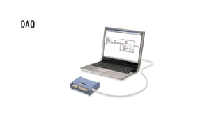
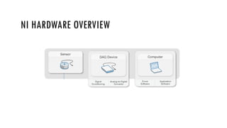
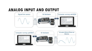
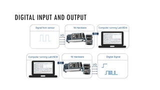
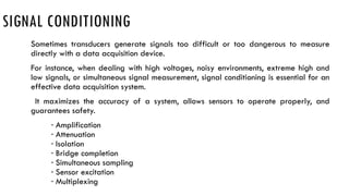
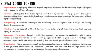
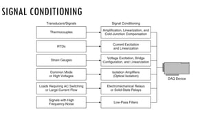
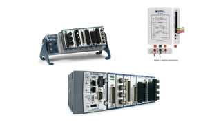
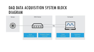
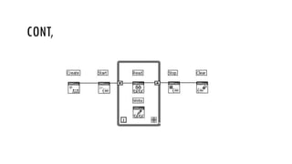
DAQ (DATA ACQUISITION)
WHAT WIKI SAYS?
INTRODUCTION
1. Data acquisition is the process of sampling signals that measure real world
physical conditions and converting the resulting samples into digital numeric
values that can be manipulated by a computer.
2. Data acquisition involves gathering signals from measurement sources and
digitizing the signals for storage, analysis, and presentation on a PC.
3. Data acquisition systems come in many different PC technology forms to offer
flexibility when choosing your system.
4. You can choose from PCI, PXI, PCI Express, PXI Express, PCMCIA, USB, wireless,
and Ethernet data acquisition for test, measurement, and automation
applications
INSTRUMENTATION SYSTEMS
Instrumentation systems can be classified into:
Analog Systems
Digital Systems
DAQ
COMPONENTS OF DATA ACQUISITION SYSTEM
• Transducers and sensors
• Signals
• Signal conditioning
• DAQ hardware
• Driver and application software
NI HARDWARE OVERVIEW
TRANSDUCERS OR SENSORS
 SENSORS is a device which detects or measures a
physical property and records, indicates, or otherwise
responds to it.
TRANSDUCERS
Data acquisition begins with the physical phenomenon to be measured.
This physical phenomenon could be the temperature of a room, the intensity of a
light source, the pressure inside a chamber, the force applied to an object, or many
other things.
A transducer is a device that converts a physical phenomenon into a measurable
electrical signal, such as voltage or current.
Transducers are synonymous with sensors in data acquisition systems.
TRANSDUCERS
Phenomenon Transducer
Temperature Thermocouple, RTD, Thermistor
Light Photo Sensor
Sound Microphone
Force and Pressure
Strain Gage
Piezoelectric Transducer
Position and Displacement Potentiometer, LVDT, Optical Encoder
Acceleration Accelerometer
pH pH Electrode
C L A S S I F I C A T I O N O F S E N S O R S
 Active sensors self generating transducers which develops their output in the
form of voltage or current Eg., thermocouples and piezoelectric accelerometers
Passive sensors in which electrical parameter R,L,C changes with changes in
input signal. It requires power supply for its operation eg., RTD, Thermister, Strain
gauge
DIFFERENT TYPES OF SENSORS
 Temperature Sensor
Temperature Sensor, the changes in the Temperature correspond to
change in its physical property like resistance or voltage.
Ex: Air Conditioner, Microwave oven
Proximity Sensor
A Proximity Sensor is a non-contact type sensor that detects the
presence of an object. Proximity Sensors can be implemented using
different techniques like Optical (like Infrared or Laser), Ultrasonic,
Hall Effect, Capacitive, Inductive, etc.
Ex: Mobile phones
DIFFERENT TYPES OF SENSORS
 Accelerometer
An accelerometer is an electromechanical device that will measure
acceleration forces. These forces may be static, like the constant force of
gravity pulling at your feet, or they could be dynamic - caused by moving
or vibrating the accelerometer
Ex: Mobile display change
IR Sensor (Infrared Sensor)
It detect/measure infrared radiation or change in the radiation from outer
source source or inbuilt source. Also sensors that uses the property of
infrared radiations to detect the changes in surrounding are termed as
infrared sensor.
Ex: Automatic Door opening
DIFFERENT TYPES OF SENSORS
 Pressure Sensor
A device for pressure measurement of gases or liquids. Pressure is an
expression of the force required to stop a fluid from expanding
Ex: Tyre air refilling mechanisms
Light Sensor
It generates an output signal indicating the intensity of light by
measuring the radiant energy that exists in a very narrow range of
frequencies basically called “light”, and which ranges in frequency
from “Infra-red” to “Visible” up to “Ultraviolet” light spectrum
Ex. Automatic Street lights
DIFFERENT TYPES OF SENSORS
 Ultrasonic Sensor
Sensor that head emits an ultrasonic wave and receives the wave
reflected back from the target. Ultrasonic Sensors measure the
distance to the target by measuring the time between the emission
and reception.
Ex: Reverse parking sensors in Cars
 Flow and Level Sensor
To detect the level of liquids and other fluids and fluidized solids
Ex: Water level, oil or fuel Level
DIFFERENT TYPES OF SENSORS
 Rotary encoder
A type of position sensor which is used for determining the angular
position of a rotating shaft. It generates an electrical signal, either
analog or digital, according to the rotational movement.
Ex: volume control knob in car media players
 Color Sensor
it detect the color of a surface. The sensors cast light (red, green, and
blue LEDs) on the objects to be tested, calculate the chromaticity
coordinates from the reflected radiation and compare them with
previously stored reference colors
Ex: Rice sorting machines
SIGNALS
The appropriate transducers convert physical phenomena into measurable signals.
However, different signals need to be measured in different ways. For this reason, it is
important to understand the different types of signals and their corresponding
attributes. Signals can be categorized into two groups:
Analog
Digital
ANALOG SIGNALS
An analog signal can exist at any value with respect to time(varies continuously) . A few examples of
analog signals include voltage, temperature, pressure, sound, and load. The three primary characteristics
of an analog signal are level, shape, and frequency
ANALOG INPUT AND OUTPUT
DIGITAL SIGNALS
A digital signal cannot take on any value with respect to time. Instead, a digital
signal has two possible levels: high and low.
DIGITAL INPUT EXAMPLE
DIGITAL INPUT AND OUTPUT
SIGNAL CONDITIONING
Sometimes transducers generate signals too difficult or too dangerous to measure
directly with a data acquisition device.
For instance, when dealing with high voltages, noisy environments, extreme high and
low signals, or simultaneous signal measurement, signal conditioning is essential for an
effective data acquisition system.
It maximizes the accuracy of a system, allows sensors to operate properly, and
guarantees safety.
· Amplification
· Attenuation
· Isolation
· Bridge completion
· Simultaneous sampling
· Sensor excitation
· Multiplexing
SIGNAL CONDITIONING
Amplification- Amplifying electrical signals improves accuracy in the resulting digitized signal
and reduces the effects of noise
Isolation- isolating the transducer signals from the computer for safety purposes. The system
being monitored may contain high-voltage transients that could damage the computer without
signal conditioning.
Multiplexing- A common technique for measuring several signals with a single measuring
device is multiplexing.
Filtering- The purpose of a filter is to remove unwanted signals from the signal that you are
trying to measure.
Transducers Excitation- Signal conditioning systems can generate excitation, which some
transducers require for operation. Strain gauges and RTDs require external voltage and
currents, respectively, to excite their circuitry into measuring physical phenomena.
Linearization- Many transducers, such as thermocouples, have a nonlinear response to changes
in the physical phenomena you measure. LabVIEW can linearize the voltage levels from
transducers so you can scale the voltages to the measured phenomena.
SIGNAL CONDITIONING
DATA ACQUISITION HARDWARE
Data acquisition hardware acts as the interface between the computer and the outside
world.
It primarily functions as a device that digitizes incoming analog signals so that the
computer can interpret them. Other data acquisition functionality includes the following:
· Analog input/output
· Digital input/output
· Counter/timers
· Multifunction - a combination of analog, digital, and counter operations on a single device
DATA ACQUISITION HARDWARE
NI provides PCI DAQ boards that plug into any desktop computer.
In addition, NI makes DAQ modules for PXI/CompactPCI, a more rugged modular
computer platform specifically for measurement and automation applications.
For distributed measurements, the NI Compact FieldPoint platform delivers modular
I/O, embedded operation, and Ethernet communication.
For portable or handheld measurements, National Instruments DAQ devices for USB
and PCMCIA work with laptops or Windows Mobile PDAs.
In addition, National Instruments has launched DAQ devices for PCI Express, the
next-generation PC I/O bus, and for PXI Express, the high-performance PXI bus.
DATA ACQUISITION SYSTEM
DATA ACQUISITION HARDWARE
DRIVER AND APPLICATION SOFTWARE
Driver Software
Software transforms the PC and the data acquisition hardware into a complete data
acquisition, analysis, and presentation tool.
Driver software is the layer of software for easily communicating with the hardware.
It forms the middle layer between the application software and the hardware.
Driver software also prevents a programmer from having to do register-level
programming or complicated commands to access the hardware functions.
DRIVER AND APPLICATION SOFTWARE
Application Software
The application layer can be either a development environment in which you build a
custom application that meets specific criteria, or it can be a configuration-based
program with preset functionality. Application software adds analysis and
presentation capabilities to driver software. To choose the right application
NI offers three development environment software products for creating complete
instrumentation, acquisition, and control applications:
· LabVIEW with graphical programming methodology
· LabWindows™/CVI for traditional C programmers
· Measurement Studio for Visual Basic, C++, and .NET
MY DAQ
DAQ DATA ACQUISITION SYSTEM BLOCK
DIAGRAM
NI MULTIFUNCTION I/O DAQ DEVICES FOR PC-
BASED MEASUREMENT SYSTEMS
DATA ACQUISITION VIS AND FUNCTIONS
DAQ Assistant Express VI
DAQmx Create Virtual Channel
DAQmx Timing
DAQmx Read
DAQmx Write
DAQmx Start
DAQmx Stop
DAQ PROGRAMMING METHODS
Simple programming using DAQ assist
Advanced programming
DAQ ASSIST CONFIGURATION TYPES
Acquire Signal
 Analog Input
 Counter Input
 Digital Input
Generate Signal
SIMPLE PROGRAMMING USING DAQ ASSIST
CONT.,
Configuring DAQmx Express VI using the DAQ Assistant (Analog
Input)
CONT.,
CONT.,
CONFIGURING DAQMX EXPRESS VI USING THE DAQ ASSISTANT
(ANALOG OUTPUT)
CONT.,
CONT.,
CONFIGURING DAQMX EXPRESS VI USING THE DAQ ASSISTANT
(COUNTER INPUT)
CONT.,
CONFIGURING DAQMX EXPRESS VI USING THE DAQ ASSISTANT
(COUNTER OUTPUT)
CONT.,
CONFIGURING DAQMX EXPRESS VI USING THE DAQ ASSISTANT
(DIGITAL I/O)
CONT.,
MEASUREMENT & AUTOMATION EXPLORER
CREATING NI-DAQMX TASKS IN MAX
CONT.,
CONT.,
CONT.,
CONT.,
CONT,

LABVIEW Data Acquisition System overview.pptx

  • 1.
  • 2.
  • 3.
    INTRODUCTION 1. Data acquisitionis the process of sampling signals that measure real world physical conditions and converting the resulting samples into digital numeric values that can be manipulated by a computer. 2. Data acquisition involves gathering signals from measurement sources and digitizing the signals for storage, analysis, and presentation on a PC. 3. Data acquisition systems come in many different PC technology forms to offer flexibility when choosing your system. 4. You can choose from PCI, PXI, PCI Express, PXI Express, PCMCIA, USB, wireless, and Ethernet data acquisition for test, measurement, and automation applications
  • 4.
    INSTRUMENTATION SYSTEMS Instrumentation systemscan be classified into: Analog Systems Digital Systems
  • 5.
  • 6.
    COMPONENTS OF DATAACQUISITION SYSTEM • Transducers and sensors • Signals • Signal conditioning • DAQ hardware • Driver and application software
  • 7.
  • 8.
  • 9.
    TRANSDUCERS OR SENSORS SENSORS is a device which detects or measures a physical property and records, indicates, or otherwise responds to it.
  • 10.
    TRANSDUCERS Data acquisition beginswith the physical phenomenon to be measured. This physical phenomenon could be the temperature of a room, the intensity of a light source, the pressure inside a chamber, the force applied to an object, or many other things. A transducer is a device that converts a physical phenomenon into a measurable electrical signal, such as voltage or current. Transducers are synonymous with sensors in data acquisition systems.
  • 11.
    TRANSDUCERS Phenomenon Transducer Temperature Thermocouple,RTD, Thermistor Light Photo Sensor Sound Microphone Force and Pressure Strain Gage Piezoelectric Transducer Position and Displacement Potentiometer, LVDT, Optical Encoder Acceleration Accelerometer pH pH Electrode
  • 12.
    C L AS S I F I C A T I O N O F S E N S O R S  Active sensors self generating transducers which develops their output in the form of voltage or current Eg., thermocouples and piezoelectric accelerometers Passive sensors in which electrical parameter R,L,C changes with changes in input signal. It requires power supply for its operation eg., RTD, Thermister, Strain gauge
  • 13.
    DIFFERENT TYPES OFSENSORS  Temperature Sensor Temperature Sensor, the changes in the Temperature correspond to change in its physical property like resistance or voltage. Ex: Air Conditioner, Microwave oven Proximity Sensor A Proximity Sensor is a non-contact type sensor that detects the presence of an object. Proximity Sensors can be implemented using different techniques like Optical (like Infrared or Laser), Ultrasonic, Hall Effect, Capacitive, Inductive, etc. Ex: Mobile phones
  • 14.
    DIFFERENT TYPES OFSENSORS  Accelerometer An accelerometer is an electromechanical device that will measure acceleration forces. These forces may be static, like the constant force of gravity pulling at your feet, or they could be dynamic - caused by moving or vibrating the accelerometer Ex: Mobile display change IR Sensor (Infrared Sensor) It detect/measure infrared radiation or change in the radiation from outer source source or inbuilt source. Also sensors that uses the property of infrared radiations to detect the changes in surrounding are termed as infrared sensor. Ex: Automatic Door opening
  • 15.
    DIFFERENT TYPES OFSENSORS  Pressure Sensor A device for pressure measurement of gases or liquids. Pressure is an expression of the force required to stop a fluid from expanding Ex: Tyre air refilling mechanisms Light Sensor It generates an output signal indicating the intensity of light by measuring the radiant energy that exists in a very narrow range of frequencies basically called “light”, and which ranges in frequency from “Infra-red” to “Visible” up to “Ultraviolet” light spectrum Ex. Automatic Street lights
  • 16.
    DIFFERENT TYPES OFSENSORS  Ultrasonic Sensor Sensor that head emits an ultrasonic wave and receives the wave reflected back from the target. Ultrasonic Sensors measure the distance to the target by measuring the time between the emission and reception. Ex: Reverse parking sensors in Cars  Flow and Level Sensor To detect the level of liquids and other fluids and fluidized solids Ex: Water level, oil or fuel Level
  • 17.
    DIFFERENT TYPES OFSENSORS  Rotary encoder A type of position sensor which is used for determining the angular position of a rotating shaft. It generates an electrical signal, either analog or digital, according to the rotational movement. Ex: volume control knob in car media players  Color Sensor it detect the color of a surface. The sensors cast light (red, green, and blue LEDs) on the objects to be tested, calculate the chromaticity coordinates from the reflected radiation and compare them with previously stored reference colors Ex: Rice sorting machines
  • 18.
    SIGNALS The appropriate transducersconvert physical phenomena into measurable signals. However, different signals need to be measured in different ways. For this reason, it is important to understand the different types of signals and their corresponding attributes. Signals can be categorized into two groups: Analog Digital
  • 19.
    ANALOG SIGNALS An analogsignal can exist at any value with respect to time(varies continuously) . A few examples of analog signals include voltage, temperature, pressure, sound, and load. The three primary characteristics of an analog signal are level, shape, and frequency
  • 20.
  • 21.
    DIGITAL SIGNALS A digitalsignal cannot take on any value with respect to time. Instead, a digital signal has two possible levels: high and low.
  • 22.
  • 23.
  • 24.
    SIGNAL CONDITIONING Sometimes transducersgenerate signals too difficult or too dangerous to measure directly with a data acquisition device. For instance, when dealing with high voltages, noisy environments, extreme high and low signals, or simultaneous signal measurement, signal conditioning is essential for an effective data acquisition system. It maximizes the accuracy of a system, allows sensors to operate properly, and guarantees safety. · Amplification · Attenuation · Isolation · Bridge completion · Simultaneous sampling · Sensor excitation · Multiplexing
  • 25.
    SIGNAL CONDITIONING Amplification- Amplifyingelectrical signals improves accuracy in the resulting digitized signal and reduces the effects of noise Isolation- isolating the transducer signals from the computer for safety purposes. The system being monitored may contain high-voltage transients that could damage the computer without signal conditioning. Multiplexing- A common technique for measuring several signals with a single measuring device is multiplexing. Filtering- The purpose of a filter is to remove unwanted signals from the signal that you are trying to measure. Transducers Excitation- Signal conditioning systems can generate excitation, which some transducers require for operation. Strain gauges and RTDs require external voltage and currents, respectively, to excite their circuitry into measuring physical phenomena. Linearization- Many transducers, such as thermocouples, have a nonlinear response to changes in the physical phenomena you measure. LabVIEW can linearize the voltage levels from transducers so you can scale the voltages to the measured phenomena.
  • 26.
  • 27.
    DATA ACQUISITION HARDWARE Dataacquisition hardware acts as the interface between the computer and the outside world. It primarily functions as a device that digitizes incoming analog signals so that the computer can interpret them. Other data acquisition functionality includes the following: · Analog input/output · Digital input/output · Counter/timers · Multifunction - a combination of analog, digital, and counter operations on a single device
  • 28.
    DATA ACQUISITION HARDWARE NIprovides PCI DAQ boards that plug into any desktop computer. In addition, NI makes DAQ modules for PXI/CompactPCI, a more rugged modular computer platform specifically for measurement and automation applications. For distributed measurements, the NI Compact FieldPoint platform delivers modular I/O, embedded operation, and Ethernet communication. For portable or handheld measurements, National Instruments DAQ devices for USB and PCMCIA work with laptops or Windows Mobile PDAs. In addition, National Instruments has launched DAQ devices for PCI Express, the next-generation PC I/O bus, and for PXI Express, the high-performance PXI bus.
  • 31.
  • 32.
  • 33.
    DRIVER AND APPLICATIONSOFTWARE Driver Software Software transforms the PC and the data acquisition hardware into a complete data acquisition, analysis, and presentation tool. Driver software is the layer of software for easily communicating with the hardware. It forms the middle layer between the application software and the hardware. Driver software also prevents a programmer from having to do register-level programming or complicated commands to access the hardware functions.
  • 34.
    DRIVER AND APPLICATIONSOFTWARE Application Software The application layer can be either a development environment in which you build a custom application that meets specific criteria, or it can be a configuration-based program with preset functionality. Application software adds analysis and presentation capabilities to driver software. To choose the right application NI offers three development environment software products for creating complete instrumentation, acquisition, and control applications: · LabVIEW with graphical programming methodology · LabWindows™/CVI for traditional C programmers · Measurement Studio for Visual Basic, C++, and .NET
  • 35.
  • 38.
    DAQ DATA ACQUISITIONSYSTEM BLOCK DIAGRAM
  • 39.
    NI MULTIFUNCTION I/ODAQ DEVICES FOR PC- BASED MEASUREMENT SYSTEMS
  • 40.
    DATA ACQUISITION VISAND FUNCTIONS
  • 41.
    DATA ACQUISITION VISAND FUNCTIONS DAQ Assistant Express VI DAQmx Create Virtual Channel DAQmx Timing DAQmx Read DAQmx Write DAQmx Start DAQmx Stop
  • 42.
    DAQ PROGRAMMING METHODS Simpleprogramming using DAQ assist Advanced programming
  • 43.
    DAQ ASSIST CONFIGURATIONTYPES Acquire Signal  Analog Input  Counter Input  Digital Input Generate Signal
  • 44.
  • 45.
    CONT., Configuring DAQmx ExpressVI using the DAQ Assistant (Analog Input)
  • 46.
  • 47.
  • 48.
    CONFIGURING DAQMX EXPRESSVI USING THE DAQ ASSISTANT (ANALOG OUTPUT)
  • 49.
  • 50.
  • 51.
    CONFIGURING DAQMX EXPRESSVI USING THE DAQ ASSISTANT (COUNTER INPUT)
  • 52.
  • 53.
    CONFIGURING DAQMX EXPRESSVI USING THE DAQ ASSISTANT (COUNTER OUTPUT)
  • 54.
  • 55.
    CONFIGURING DAQMX EXPRESSVI USING THE DAQ ASSISTANT (DIGITAL I/O)
  • 56.
  • 57.
  • 58.
  • 59.
  • 60.
  • 61.
  • 62.
  • 63.

Editor's Notes

  • #5 DAQ .Data Acquisition system is to measure or generate real-world physical signals. Data acquisition involves gathering signals from measurement sources and digitizing the signal for storage, analysis and presentation on a personal computer (PC). Data acquisition systems come in many different PC technology forms for great flexibility.
  • #38 DAQ (Data Acquisition) is an important process of collecting the necessary information about the electrical and physical phenomenon happening in the experiment or project. The collected information helps us understand how the experiment goes and what kind of performance the system demonstrates. Data acquisition is performed via sensors, measuring devices, instrumentation, and computers, which together consists of a DAQ (data acquisition) system. The above diagram shows that a DAQ (data acquisition) system consists of sensors, DAQ device and the computer. The DAQ device performs the functions of signal conditioning and ADC (Analog-to-Digital) conversion. The computer provides the platform to run the application of the DAQ system, which requires the special driver software to be installed on the computer. The sensors or transducers interact with the system under measurement via contact or non-contact ways and convert the physical values, such as temperature or pressure to electrical signals, voltage or current depending on applications. The three function blocks must be connected or interfaced to transmit signals between them. This function is carried out by Data Bus based on protocols, such as RS232, RS485, Ethernet, USB, or other field buses. Professional DAQ systems are built for specific applications and usually can be very expensive. NI offers different products for various applications and customer needs, such as PC-based systems, CompactRIO system and PXI systems.
  • #39 In a PC-based measurement and control system, the DAQ system is connected to the PC or laptop via USB or Ethernet. The DAQ systems have two main architectures, multifunction IO devices and CompactDAQ Chassis. With a PC-based DAQ system, we can save time for setup, access to the measurements and change configurations of channels, data rates and output rates with ease. It also allows us to build on the measurement system with NI LabVIEW to automate the measurements, perform complicated analysis and integrate instruments from other vendors. In a PC-based measurement and control system, the DAQ system is connected to the PC or laptop via USB or Ethernet. The DAQ systems have two main architectures, multifunction IO devices and CompactDAQ Chassis. With a PC-based DAQ system, we can save time for setup, access to the measurements and change configurations of channels, data rates and output rates with ease. It also allows us to build on the measurement system with NI LabVIEW to automate the measurements, perform complicated analysis and integrate instruments from other vendors. Multifunction IO DAQ Devices provide combinations of analog I/O, digital I/O and counter/timer functionality in a single device for computer-based systems. The Multifunction I/O devices offer varying channels, sample rates, output rates, and many other special features to meet common data acquisition requirements. The NI Multifunction I/O Devices can be used for industry application as well as automated data collection in laboratory environment for research or design verifications. The included DAQExpress software provides basic measurement and analysis and the NI DAQmx driver provides the ability to create customized automated measurement and control applications via supported NI programming environments
  • #40 In block diagram window, The Measurement I O DAQmxData Acquisition palette contains all of the VIs, and other tools that you will need to explore DAQ, or Data Acquisitionone of LabVIEW's great strengths. In fact, LabVIEW's DAQ capabilities might even be the reason why you chose to learn LabVIEWso that you could quickly acquire data and generate signals to measure, control, turn on and off, or blow up stuff in the external world!
  • #41 Use the DAQmx - Data Acquisition VIs with NI-DAQmx hardware devices to develop instrumentation, acquisition, and control applications. DAQ Assistant Express VI, which is used to Creates, edits, and runs tasks using NI-DAQmx. Second, DAQmx Create Virtual Channel, which is used to Creates a virtual channel or set of virtual channels and adds them to a task. The instances of this polymorphic VI correspond to the I/O type of the channel, such as analog input, digital output, or counter output; the measurement or generation to perform, such as temperature measurement, voltage generation, or event counting; and in some cases, the sensor to use, such as a thermocouple or RTD for temperature measurements. DAQmx Timing, which is used to Configures the number of samples to acquire or generate and creates a buffer when needed. The instances of this polymorphic VI correspond to the type of timing to use for the task. Next is DAQmx Read- used to, Reads samples from the task or virtual channels you specify. The instances of this polymorphic VI specify what format of samples to return, whether to read a single sample or multiple samples at once, and whether to read from one or multiple channels… DAQmx Write-used to, Writes samples to the task or virtual channels you specify. The instances of this polymorphic VI specify the format of the samples to write, whether to write one or multiple samples, and whether to write to one or multiple channels. Next is DAQmx Start Task, which is used to Transitions the task to the running state to begin the measurement or generation. Using this VI is required for some applications and is optional for others. THE last important function is, DAQmx Stop Task- which is used to Stops the task and returns it to the state the task was in before the DAQmx Start Task VI ran or the DAQmx Write VI ran with the autostart input set to TRUE.
  • #42 We can program the DAQ in two different methods, one is by Simple programming using DAQ assist, and the other one is, Advanced programming
  • #43 DAQ Assistant is a graphical interface for interactively creating, editing, and running NI-DAQmx virtual channels and tasks. An NI-DAQmx virtual channel consists of a physical channel on a DAQ device and the configuration information for this physical channel, such as input range and custom scaling. An NI-DAQmx task is a collection of virtual channels, timing and triggering information, and other properties regarding the acquisition or generation. In the following figure, DAQ Assistant is configured to perform a finite strain measurement. Daq assist can configured into different types. Majorly classified into: Acquire Signal. Generate Signal. In Acquire Signal we have Analog Input, Counter Input, Digital Input.
  • #44 Once you have located the DAQ Assistant Express VI in the appropriate location, select it from the palette and drop it on the block diagram of your VI. By default, the properties page should pop up, as shown in figure, allowing you to configure your task. The first step is to select your type of measurement
  • #45 First lets check the analog input. There are several options for an analog input acquisition. For this VI, we will step through a simple Analog Input >> Voltage measurement. Once you have selected Voltage as the type of Analog Input acquisition, you will have the option to select which channels you want to acquire from. The first screen you will see will allow you to select the physical channels that you want to acquire from, by creating local channels .
  • #46 Once you have selected the channel(s), click the Finish button. This will bring up the analog input task configuration page as shown in fig. Here you can set up your task to acquire data exactly the way you want. You can set your Signal Input Range to a range suitable for the signal(s) you are acquiring. You can set the Terminal Configuration to the mode of your acquisition (Differential, Reference Single Ended, Non-Reference Single Ended). The Custom Scaling option allows you to create a new scale or apply already existing scales. On the Task Timing tab, you can set how you will acquire your data. You can Acquire 1 Sample at a time (software timed), Acquire N Samples, which acquires a finite set of samples (hardware timed), or Acquire Continuously (hardware-timed). If you select Acquire N Samples for a finite scan or Acquire Continuously for continuous acquisition, you will have the option to specify how many Samples To Read and the Rate of your acquisition. Under the Advanced Clock Settings section, you can specify whether you will be using an internal or an external clock. If you select external for your clock, you will have the option to select the active edge and what pin the external clock will be connected to. In the Task Triggering tab, you can specify a Start and/or a Reference Trigger. Once you are finished configuring your task, click the OK button.
  • #47 This saves your settings and returns you to your block diagram where you will see your configured DAQ Assistant Express VI. Your data will be available on the data output. You can wire this output to an analysis VI, file I/O VI, directly to an indicator, etc.  You can Build the front panel and block diagram shown in Figures, with while loop and array and graph as indicators. In this Convert from Dynamic Data Express>>Signal Manipulation palette. This Express VI converts the dynamic data type to a numeric scalar. It has been configured to return a single scalar floating point number from channel 0.
  • #48 When you select Analog Output for your type of measurement, you will have a couple of options regarding what type of output you want to do. This document will focus on a simple voltage output . Once you have selected Voltage as the Analog Output measurement type, you will be able to select which output channel(s) you want to use. As with Analog Input, you will be able to select physical channels, through creating local channels, or already created DAQmx Global Channels. You will see a window similar to the window in analog input configuration., except the channels available will be your analog output channels.
  • #49 Once you have your channel(s) selected, you will come to the analog output task configuration page. Similar to an analog input task, you can specify your Output Range, Custom Scaling, Task Timing and Task Triggering. However, there is one option that is not present in an analog input task, and that is the Use timing from waveform data option under the Task Timing tab. By default this option is selected and the Samples to Write and Rate are grayed out. This is because the timing information is automatically extracted from the waveform input to the configured DAQ Assistant Express VI, eliminating the need to manually specify the timing information. However, if you deselect the Use timing from waveform data option, then you will have the ability to set Samples to Write, Rate, and Advanced Clock Settings. Once you have configured your task, click OK to save your settings and return to your block diagram. 
  • #50 Now, simply wire in your data to the data input and run your VI to output your voltages as shown in figure.
  • #51 When you select Counter Input as the type of measurement, you will have several options. This VI will focus on an Edge Count measurement. Once you select your type of counter input, you will have the option of selecting the counter you want to use. As with previous examples, you can select to create new local channels or copy already existing DAQmx Global Channels. You will see a window similar to Figure 5 or 6 above, except the channels available will be your counter channels.
  • #52 Once you have selected the counter channel, you will come to the task configuration page as shown in figure. Here you can configure the Active Edge to be rising or falling. You can set the Initial Count of the count register. You can also select the Count Direction to be Count Up, Count Down, or Externally Controlled. If you select Externally Controlled, the counter will either count up or down depending upon the signal connected to the Up/Down pin of your counter. This is typically used for quadrature encoders (refer to Quadrature Encoder Tutorial linked below for more information). Notice below the Count Direction option there is a statement instructing you to connect the signal to the appropriate PFI pin on your data acquisition board. By default, the Count Edges option is selected in the Task Timing section. Notice that when the Count Edges option is selected, Samples To Read, Rate, and Clock Settings are grayed out. This is because the Count Edges operation is software timed and does not require an external clock. However, if you choose either Count N Samples (Finite) or Count N Samples (Continuous), which are both buffered operations, you will be able to specify the number of Samples To Read, Rate, and Clock Settings. That is to say, Count N Samples (Finite) and Count N Samples (Continuous) are hardware timed acquisitions, and you will have to provide an external clock signal, to the pin specified under Clock Source, in order to perform the buffered operation.
  • #53 You can use the DAQmx Express VI to generate output on your counters in the form of digital pulses. If you select Counter Output from the original DAQ Assistant window , you will have one option in the following screen, and that is Pulse Output.
  • #54 Once you select Pulse Output, you will be able to select which counter(s) you want to you use in this pulse generation operation. You will see a window, where the channels available will be your counter channels. Once you have selected your counter(s) you will be able to configure the counter output task as shown in figure. Here you can set the Pulse Settings, where you specify how long the pulse is high and low with the High Time and the Low Time, respectively. You can also specify the Idle State and Initial Delay. The Idle State determines whether the pulse is active high or active low. Typically, the idle state is generated first followed by the active state. The Initial Delay allows you to specify a time to delay before generating the first pulse. Under the Task Timing section, you can specify whether you want to generate a Single Pulse, a Finite Pulse Train, or a Continuous Pulse Train. If Finite Pulse Train is selected, then the option to set the number of Pulses is available. Click OK to save the task and return to the block diagram.
  • #55 If you want to use the DAQmx Express VI for digital I/O, you have several options. You can select Line Input, Port Input, Line Output, or Port Output. In this document, we will be discussing the Line Input task, but the other three operations are set up similarly. Once you have chosen Line Input, you will have the option to create a local channel and select individual lines or copy existing DAQmx Global Virtual Channels. You will see digital channels.
  • #56 Once the channels have been defined or selected, click Next to go to the task configuration page as show in figure. Here you can choose to invert 1 or more of the digital lines that you have specified. Click OK to save the task and return to the block diagram.
  • #57 NI Measurement & Automation Explorer (MAX) provides access to your NI hardware. It is a free piece of software that cannot be downloaded by itself but is included, and automatically installed, with all NI drivers. With MAX, you can:  Configure your NI hardwarE and software Export OR Import the System Configuration Create and edit channels, tasks, interfaces, scales, and virtual instruments. Create Simulated Devices . Execute system diagnostics and run test panels . View devices/instruments connected to your system and software installed on your system . how to create virtual channels in MAX. These virtual channels correlate with physical channels on your DAQ device that can be read from or written to in LabVIEW using the NI-DAQmx VIs. Now you'll learn about tasks, an even more powerful framework that makes building your DAQ application easier.
  • #58 First open MAX. To create an NI-DAQmx Task in MAX, right-click on the Data Neighbourhood in the Configuration tree and select Create New . . . from the pop-up menu. In the resulting dialog, select NI-DAQmx Task and press the Next button.
  • #59 Select a measurement type. Select one or more physical channels from the list of devices and physical channels that support the measurement type you have selected, and press the Next button. Edit the name of the task (or use the default namethis can be changed later) and press the Finish button
  • #60 Your new task will appear beneath the My System>>Data Neighborhood>> NI-DAQmx Tasks in MAX's Configuration tree . Click on the task with your mouse to view the task's configuration dialog. You can now configure and test the specific functionality of your task. Congratulationsyou're well on your way to using NI-DAQmx tasks in LabVIEW!
  • #61 Now that you know how to create and access NI-DAQmx Tasks in MAX, you will learn how to access them from within LabVIEW. Simply place a DAQmx Task Name constant. (found on the Measurement I/O>>DAQmxData Acquisition palette) onto the block diagram, as shown in Figure. Using the Operating tool, you can select an NI-DAQmx task that you have created in MAX, by clicking on the DAQmx Task Name constant, as shown in Figure .
  • #62 If you would like to create a new NI-DAQmx task in MAX, select the Browse . . . option in the DAQmx Task Name drop-down list, and then choose Create New . . . >>Max Task (see Figure). This will open the NI-DAQmx task wizardwhich you learned about earlier in the section, "Creating NI-DAQmx Tasks in MAX"where you can create a new NI-DAQmx task, which may then be selected from the DAQmx Task Name constant.
  • #63 Before we get into the details of how each individual DAQmx VI works, you will want to see a bird's eye view of the DAQmx VIs and methodology. Fortunately, using NI-DAQmx tasks in LabVIEW is very easyit consists of the following steps: 1. Create a task (or reference a MAX DAQmx task). 2. Start the task. 3. Read or Write, and repeat as necessary. 4. Stop the task. 5. Clear the task. Note:For some measurements and generations, we will need to configure timing, triggering, and other task properties before starting the task. And also, we may need to wait for a task to complete before clearing it..