1
Boolean Algebra &Logic Gates
Presented by
A. Josekin
Assistant Professor
Department of Computer Science
2.
2
Objectives
• Understand therelationship between Boolean logic
and digital computer circuits.
• Learn how to design simple logic circuits.
• Understand how digital circuits work together to
form complex computer systems.
3.
3
Boolean Algebra
• Booleanalgebra is a mathematical system for
the manipulation of variables that can have
one of two values.
– In formal logic, these values are “true” and “false.”
– In digital systems, these values are “on” and “off,”
1 and 0, or “high” and “low.”
• Boolean expressions are created by
performing operations on Boolean variables.
– Common Boolean operators include AND, OR,
and NOT.
4.
4
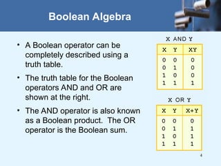
Boolean Algebra
• ABoolean operator can be
completely described using a
truth table.
• The truth table for the Boolean
operators AND and OR are
shown at the right.
• The AND operator is also known
as a Boolean product. The OR
operator is the Boolean sum.
5.
5
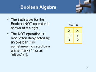
Boolean Algebra
• Thetruth table for the
Boolean NOT operator is
shown at the right.
• The NOT operation is
most often designated by
an overbar. It is
sometimes indicated by a
prime mark ( ‘ ) or an
“elbow” (
).
6.
6
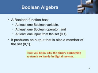
Boolean Algebra
• ABoolean function has:
• At least one Boolean variable,
• At least one Boolean operator, and
• At least one input from the set {0,1}.
• It produces an output that is also a member of
the set {0,1}.
Now you know why the binary numbering
system is so handy in digital systems.
7.
7
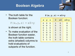
Boolean Algebra
• Thetruth table for the
Boolean function:
is shown at the right.
• To make evaluation of the
Boolean function easier,
the truth table contains
extra (shaded) columns to
hold evaluations of
subparts of the function.
8.
8
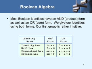
Boolean Algebra
• MostBoolean identities have an AND (product) form
as well as an OR (sum) form. We give our identities
using both forms. Our first group is rather intuitive:
9.
9
Boolean Algebra
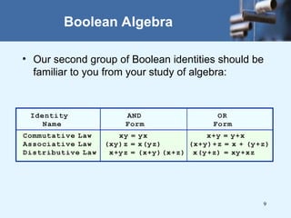
• Oursecond group of Boolean identities should be
familiar to you from your study of algebra:
10.
10
Boolean Algebra
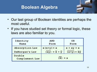
• Ourlast group of Boolean identities are perhaps the
most useful.
• If you have studied set theory or formal logic, these
laws are also familiar to you.
11.
11
Boolean Algebra
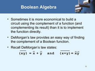
• Sometimesit is more economical to build a
circuit using the complement of a function (and
complementing its result) than it is to implement
the function directly.
• DeMorgan’s law provides an easy way of finding
the complement of a Boolean function.
• Recall DeMorgan’s law states:
12.
12
• We havelooked at Boolean functions in abstract
terms.
• In this section, we see that Boolean functions are
implemented in digital computer circuits called gates.
• A gate is an electronic device that produces a result
based on two or more input values.
– In reality, gates consist of one to six transistors, but digital
designers think of them as a single unit.
– Integrated circuits contain collections of gates suited to a
particular purpose.
Logic Gates
13.
13
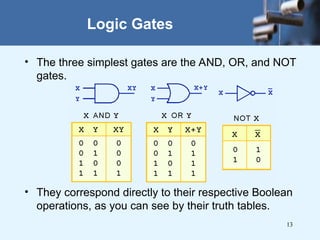
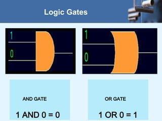
• The threesimplest gates are the AND, OR, and NOT
gates.
• They correspond directly to their respective Boolean
operations, as you can see by their truth tables.
Logic Gates
15
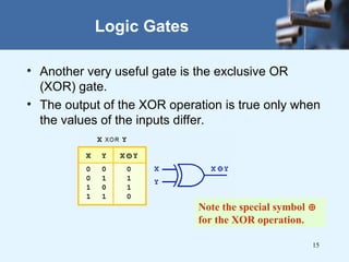
• Another veryuseful gate is the exclusive OR
(XOR) gate.
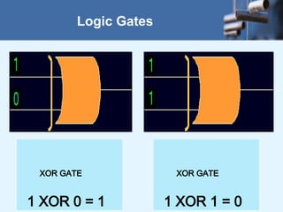
• The output of the XOR operation is true only when
the values of the inputs differ.
Logic Gates
Note the special symbol
for the XOR operation.
17
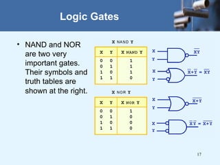
• NAND andNOR
are two very
important gates.
Their symbols and
truth tables are
shown at the right.
Logic Gates
18.
18
Logic Gates
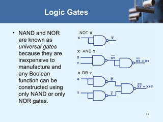
• NANDand NOR
are known as
universal gates
because they are
inexpensive to
manufacture and
any Boolean
function can be
constructed using
only NAND or only
NOR gates.
19.
19
Logic Gates
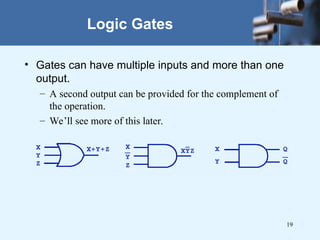
• Gatescan have multiple inputs and more than one
output.
– A second output can be provided for the complement of
the operation.
– We’ll see more of this later.
20.
20
Digital Components
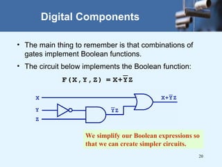
• Themain thing to remember is that combinations of
gates implement Boolean functions.
• The circuit below implements the Boolean function:
We simplify our Boolean expressions so
that we can create simpler circuits.
21.
21
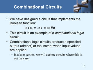
Combinational Circuits
• Wehave designed a circuit that implements the
Boolean function:
• This circuit is an example of a combinational logic
circuit.
• Combinational logic circuits produce a specified
output (almost) at the instant when input values
are applied.
– In a later section, we will explore circuits where this is
not the case.
22.
22
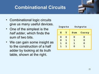
Combinational Circuits
• Combinationallogic circuits
give us many useful devices.
• One of the simplest is the
half adder, which finds the
sum of two bits.
• We can gain some insight as
to the construction of a half
adder by looking at its truth
table, shown at the right.
23.
23
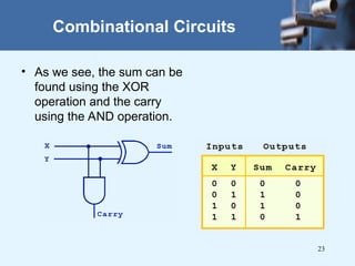
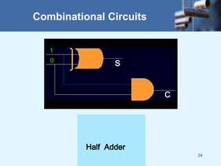
Combinational Circuits
• Aswe see, the sum can be
found using the XOR
operation and the carry
using the AND operation.
25
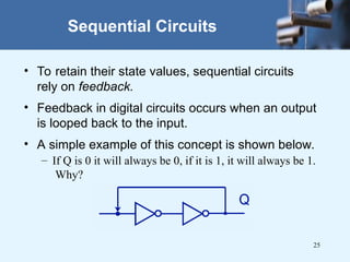
Sequential Circuits
• Toretain their state values, sequential circuits
rely on feedback.
• Feedback in digital circuits occurs when an output
is looped back to the input.
• A simple example of this concept is shown below.
– If Q is 0 it will always be 0, if it is 1, it will always be 1.
Why?
26.
26
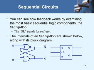
Sequential Circuits
• Youcan see how feedback works by examining
the most basic sequential logic components, the
SR flip-flop.
– The “SR” stands for set/reset.
• The internals of an SR flip-flop are shown below,
along with its block diagram.
27.
27
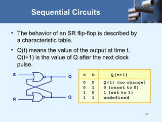
Sequential Circuits
• Thebehavior of an SR flip-flop is described by
a characteristic table.
• Q(t) means the value of the output at time t.
Q(t+1) is the value of Q after the next clock
pulse.
29
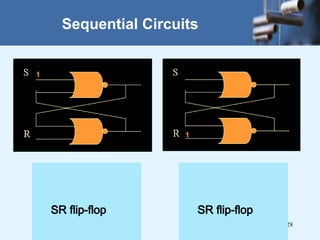
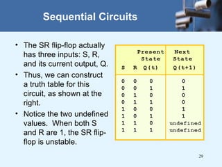
Sequential Circuits
• TheSR flip-flop actually
has three inputs: S, R,
and its current output, Q.
• Thus, we can construct
a truth table for this
circuit, as shown at the
right.
• Notice the two undefined
values. When both S
and R are 1, the SR flip-
flop is unstable.
30.
30
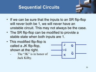
Sequential Circuits
• Ifwe can be sure that the inputs to an SR flip-flop
will never both be 1, we will never have an
unstable circuit. This may not always be the case.
• The SR flip-flop can be modified to provide a
stable state when both inputs are 1.
• This modified flip-flop is
called a JK flip-flop,
shown at the right.
- The “JK” is in honor of
Jack Kilby.
31.
31
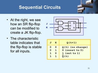
Sequential Circuits
• Atthe right, we see
how an SR flip-flop
can be modified to
create a JK flip-flop.
• The characteristic
table indicates that
the flip-flop is stable
for all inputs.
32.
32
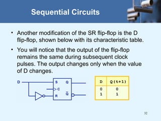
Sequential Circuits
• Anothermodification of the SR flip-flop is the D
flip-flop, shown below with its characteristic table.
• You will notice that the output of the flip-flop
remains the same during subsequent clock
pulses. The output changes only when the value
of D changes.
33.
33
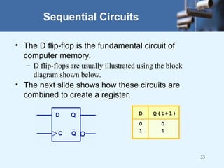
Sequential Circuits
• TheD flip-flop is the fundamental circuit of
computer memory.
– D flip-flops are usually illustrated using the block
diagram shown below.
• The next slide shows how these circuits are
combined to create a register.
34.
34
• Computers areimplementations of Boolean logic.
• Boolean functions are completely described by
truth tables.
• Logic gates are small circuits that implement
Boolean operators.
• The basic gates are AND, OR, and NOT.
– The XOR gate is very useful in parity checkers and
adders.
• The “universal gates” are NOR, and NAND.
Conclusion
35.
35
• Computer circuitsconsist of combinational logic
circuits and sequential logic circuits.
• Combinational circuits produce outputs (almost)
immediately when their inputs change.
• Sequential circuits require clocks to control their
changes of state.
• The basic sequential circuit unit is the flip-flop:
The behaviors of the SR, JK, and D flip-flops
are the most important to know.
Conclusion


![Lecture of information technology 1-COA-2015[1].pptx](https://cdn.slidesharecdn.com/ss_thumbnails/lec1-coa-20151-250806170123-c25a8fe6-thumbnail.jpg?width=640&height=640&fit=bounds)


