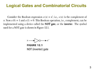
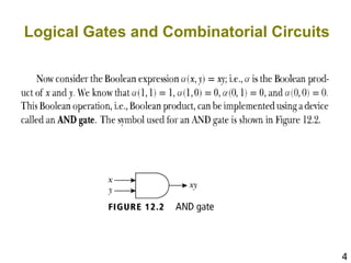
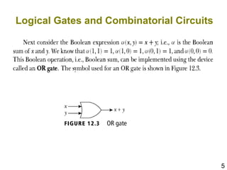
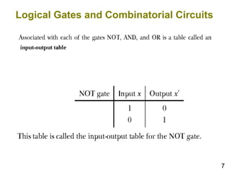
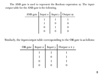
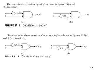
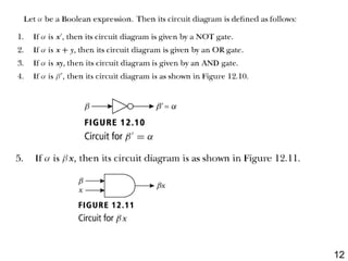
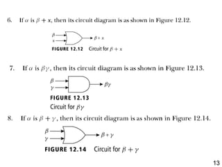
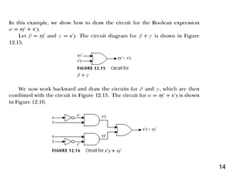
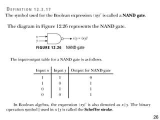
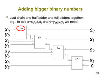
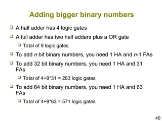
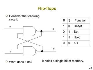
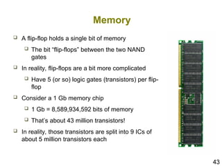
Chapter 10.3:
Logic Gates
Based on Slides from
Discrete Mathematical Structures:
Theory and Applications
and by Aaron Bloomfield
2
Learning Objectives
 Explore the application of Boolean algebra in
the design of electronic circuits. The basic
elements of circuits are gates. Each type of
gate implements a Boolean operation.
 We will study combinational circuits - the
circuits whose output depends only on the
input and not on the current state of the
circuit (no memory).
3
Logical Gates and Combinatorial Circuits
4
Logical Gates and Combinatorial Circuits
5
Logical Gates and Combinatorial Circuits
6
Logical Gates and Combinatorial Circuits
 In circuitry theory, NOT, AND, and OR gates
are the basic gates. Any circuit can be
designed using these gates. The circuits
designed depend only on the inputs, not on
the output. In other words, these circuits have
no memory. Also these circuits are called
combinatorial circuits.
 The symbols NOT gate, AND gate, and OR gate
are also considered as basic circuit symbols,
which are used to build general circuits.
7
Logical Gates and Combinatorial Circuits
8
9
10
11
12
13
14
15
16
Draw a circuit diagram for  = (xy' + x'y)z.
17
18
19
20
A circuit for two light switches
EXAMPLE 3, p. 714
 F(x,y)=1 when the light is on
 F(x,y)=0 when the light is off
 When both switches are closed, the light is on:
F(1,1)=1, this implies
 When we open one switch, the light is off:
F(1,0)=F(0,1)=0
 When the other switch is also open, the light is on:
F(0,0)=1
21
Thus, we get:
x y F(x,y)
1 1 1
1 0 0
0 1 0
0 0 1
Which Boolean expression is given by F?
Draw a circuit for F,
i.e., a circuit to control two light switches.
F(x,y) = xy + x'y'
22
23
24
25
26
27
28
29
30
31
Logical Gates and Combinatorial Circuits
 A NOT gate can be
implemented using
a NAND gate (a).
 An AND gate can be
implemented using
NAND gates (b).
 An OR gate can be
implemented using
NAND gates (c).
32
Logical Gates and Combinatorial Circuits
 Any circuit which is designed by using NOT,
AND, and OR gates can also be designed
using only NAND gates.
 Any circuit which is designed by using NOT,
AND, and OR gates can also be designed
using only NOR gates.
33
Adders: Logical gates to add two numbers
 We need to use a circuit
with more than one
output, which clearly
more powerful than a
Boolean expression.
34
How to add binary numbers
 Consider adding two 1-bit binary numbers x and y
 0+0 = 0
 0+1 = 1
 1+0 = 1
 1+1 = 10
 Carry is x AND y
 Sum is x XOR y
 The circuit to compute this is called a half-adder
x y Carry Sum
0 0 0 0
0 1 0 1
1 0 0 1
1 1 1 0
35
x y s c
1 1 0 1
1 0 1 0
0 1 1 0
0 0 0 0
= s (sum)
c (carry)
36
x 1 1 1 1 0 0 0 0
y 1 1 0 0 1 1 0 0
c 1 0 1 0 1 0 1 0
s (sum) 1 0 0 1 0 1 1 0
c (carry) 1 1 1 0 1 0 0 0
HA
X
Y
S
C
HA
X
Y
S
C
x
y
c
c
s
HA
X
Y
S
C
HA
X
Y
S
C
x
y
c
A full adder is a circuit that accepts as input thee bits x, y, and c, and
produces as output the binary sum cs of a, b, and c.
37
The full adder
 The full circuitry of the full adder
x
y
s
c
c
38
 We can use a half-adder and full adders to
compute the sum of two Boolean numbers
1 1 0 0
+ 1 1 1 0
0
1
0
?
0
0
1
Adding bigger binary numbers
39
Adding bigger binary numbers
 Just chain one half adder and full adders together,
e.g., to add x=x3x2x1x0 and y=y3y2y1y0 we need:
HA
X
Y
S
C
FA
C
Y
X
S
C
FA
C
Y
X
S
C
FA
C
Y
X
S
C
x1
y1
x2
y2
x3
y3
x0
y0
s0
s1
s2
s3
c
40
Adding bigger binary numbers
 A half adder has 4 logic gates
 A full adder has two half adders plus a OR gate
 Total of 9 logic gates
 To add n bit binary numbers, you need 1 HA and n-1 FAs
 To add 32 bit binary numbers, you need 1 HA and 31
FAs
 Total of 4+9*31 = 283 logic gates
 To add 64 bit binary numbers, you need 1 HA and 63
FAs
 Total of 4+9*63 = 571 logic gates
41
More about logic gates
 To implement a logic gate in hardware, you use a
transistor
 Transistors are all enclosed in an “IC”, or
integrated circuit
 The current Intel Pentium IV processors have 55
million transistors!
42
Flip-flops
 Consider the following
circuit:
 What does it do?
R
S
Q
Q’
R S Function
1 0 Reset
0 1 Set
1 1 Hold
0 0 1/1
It holds a single bit of memory.
43
Memory
 A flip-flop holds a single bit of memory
 The bit “flip-flops” between the two NAND
gates
 In reality, flip-flops are a bit more complicated
 Have 5 (or so) logic gates (transistors) per flip-
flop
 Consider a 1 Gb memory chip
 1 Gb = 8,589,934,592 bits of memory
 That’s about 43 million transistors!
 In reality, those transistors are split into 9 ICs of
about 5 million transistors each

Logic gates and combinational logic circuits.ppt

  • 1.
    Chapter 10.3: Logic Gates Basedon Slides from Discrete Mathematical Structures: Theory and Applications and by Aaron Bloomfield
  • 2.
    2 Learning Objectives  Explorethe application of Boolean algebra in the design of electronic circuits. The basic elements of circuits are gates. Each type of gate implements a Boolean operation.  We will study combinational circuits - the circuits whose output depends only on the input and not on the current state of the circuit (no memory).
  • 3.
    3 Logical Gates andCombinatorial Circuits
  • 4.
    4 Logical Gates andCombinatorial Circuits
  • 5.
    5 Logical Gates andCombinatorial Circuits
  • 6.
    6 Logical Gates andCombinatorial Circuits  In circuitry theory, NOT, AND, and OR gates are the basic gates. Any circuit can be designed using these gates. The circuits designed depend only on the inputs, not on the output. In other words, these circuits have no memory. Also these circuits are called combinatorial circuits.  The symbols NOT gate, AND gate, and OR gate are also considered as basic circuit symbols, which are used to build general circuits.
  • 7.
    7 Logical Gates andCombinatorial Circuits
  • 8.
  • 9.
  • 10.
  • 11.
  • 12.
  • 13.
  • 14.
  • 15.
  • 16.
    16 Draw a circuitdiagram for  = (xy' + x'y)z.
  • 17.
  • 18.
  • 19.
  • 20.
    20 A circuit fortwo light switches EXAMPLE 3, p. 714  F(x,y)=1 when the light is on  F(x,y)=0 when the light is off  When both switches are closed, the light is on: F(1,1)=1, this implies  When we open one switch, the light is off: F(1,0)=F(0,1)=0  When the other switch is also open, the light is on: F(0,0)=1
  • 21.
    21 Thus, we get: xy F(x,y) 1 1 1 1 0 0 0 1 0 0 0 1 Which Boolean expression is given by F? Draw a circuit for F, i.e., a circuit to control two light switches. F(x,y) = xy + x'y'
  • 22.
  • 23.
  • 24.
  • 25.
  • 26.
  • 27.
  • 28.
  • 29.
  • 30.
  • 31.
    31 Logical Gates andCombinatorial Circuits  A NOT gate can be implemented using a NAND gate (a).  An AND gate can be implemented using NAND gates (b).  An OR gate can be implemented using NAND gates (c).
  • 32.
    32 Logical Gates andCombinatorial Circuits  Any circuit which is designed by using NOT, AND, and OR gates can also be designed using only NAND gates.  Any circuit which is designed by using NOT, AND, and OR gates can also be designed using only NOR gates.
  • 33.
    33 Adders: Logical gatesto add two numbers  We need to use a circuit with more than one output, which clearly more powerful than a Boolean expression.
  • 34.
    34 How to addbinary numbers  Consider adding two 1-bit binary numbers x and y  0+0 = 0  0+1 = 1  1+0 = 1  1+1 = 10  Carry is x AND y  Sum is x XOR y  The circuit to compute this is called a half-adder x y Carry Sum 0 0 0 0 0 1 0 1 1 0 0 1 1 1 1 0
  • 35.
    35 x y sc 1 1 0 1 1 0 1 0 0 1 1 0 0 0 0 0 = s (sum) c (carry)
  • 36.
    36 x 1 11 1 0 0 0 0 y 1 1 0 0 1 1 0 0 c 1 0 1 0 1 0 1 0 s (sum) 1 0 0 1 0 1 1 0 c (carry) 1 1 1 0 1 0 0 0 HA X Y S C HA X Y S C x y c c s HA X Y S C HA X Y S C x y c A full adder is a circuit that accepts as input thee bits x, y, and c, and produces as output the binary sum cs of a, b, and c.
  • 37.
    37 The full adder The full circuitry of the full adder x y s c c
  • 38.
    38  We canuse a half-adder and full adders to compute the sum of two Boolean numbers 1 1 0 0 + 1 1 1 0 0 1 0 ? 0 0 1 Adding bigger binary numbers
  • 39.
    39 Adding bigger binarynumbers  Just chain one half adder and full adders together, e.g., to add x=x3x2x1x0 and y=y3y2y1y0 we need: HA X Y S C FA C Y X S C FA C Y X S C FA C Y X S C x1 y1 x2 y2 x3 y3 x0 y0 s0 s1 s2 s3 c
  • 40.
    40 Adding bigger binarynumbers  A half adder has 4 logic gates  A full adder has two half adders plus a OR gate  Total of 9 logic gates  To add n bit binary numbers, you need 1 HA and n-1 FAs  To add 32 bit binary numbers, you need 1 HA and 31 FAs  Total of 4+9*31 = 283 logic gates  To add 64 bit binary numbers, you need 1 HA and 63 FAs  Total of 4+9*63 = 571 logic gates
  • 41.
    41 More about logicgates  To implement a logic gate in hardware, you use a transistor  Transistors are all enclosed in an “IC”, or integrated circuit  The current Intel Pentium IV processors have 55 million transistors!
  • 42.
    42 Flip-flops  Consider thefollowing circuit:  What does it do? R S Q Q’ R S Function 1 0 Reset 0 1 Set 1 1 Hold 0 0 1/1 It holds a single bit of memory.
  • 43.
    43 Memory  A flip-flopholds a single bit of memory  The bit “flip-flops” between the two NAND gates  In reality, flip-flops are a bit more complicated  Have 5 (or so) logic gates (transistors) per flip- flop  Consider a 1 Gb memory chip  1 Gb = 8,589,934,592 bits of memory  That’s about 43 million transistors!  In reality, those transistors are split into 9 ICs of about 5 million transistors each