Download to read offline


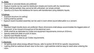
![• Natural ventilation is the procedure of entering fresh air into a home from outside. This new air, forces
the dirty, warm air in the rooms out by the opening in the roof. This can be operated without mechanical
assistance.
• Natural ventilation is one of the most practical techniques to decrease energy usage in buildings. It
utilizes the natural power of wind and buoyancy to enter fresh air and spread it in buildings for the
occupants. Natural ventilation is operated by pressure varieties between one section of a building and
another, or between the outside and inside.
• Natural ventilation can provide a sufficient supply of breathing air, adequate ventilation of pollutants,
enough thermal conditioning, and humidity waste through a well-connection to the dynamics of the
environment. Designers usually select natural ventilation because it decreases carbon production and
is cheaper to install and run than full mechanical ventilation.
• Natural Ventilation and human comfort are related together
TYPES OF VENTILATION:
1. WIND OPERATED [CROSS VENTILATION]
2. BUOYANCY OPERATED [STACK EFFECT]](https://image.slidesharecdn.com/barrierfreedesignandservicesliteraturestudy-210515133724/85/Barrierfree-design-and-services-literature-study-51-320.jpg)


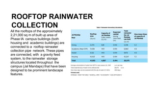
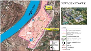
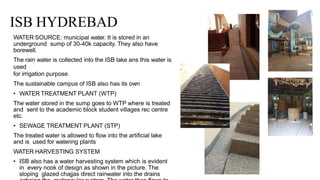
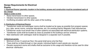
![INFERENCES
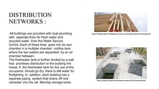
• Rooftop rain water and surface run off rain water can be collected through collection pipe networks and storm
water drains and stored in rain water storage structures. This rain water can be used for irrigation, or can even be
used as drinking water after proper treatment.
• The collection pipe networks can be gravity fed systems.
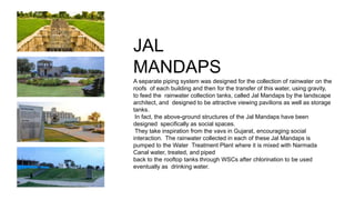
• The rain water collection structures were designed as social gathering spaces taking inspiration from the vavs
(step wells) of Gujarat.[site context]
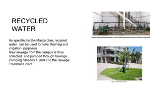
• Dual plumbing system is followed for fresh water and recycled water.
• The water tank for fire fighting system never goees dry , even when the fresh water tank does.
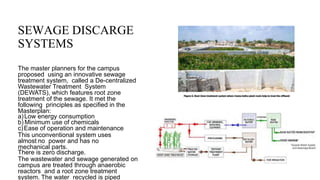
• The DEWATS system is a very efficient and eco friendly way to treat water. It can be incorporated in the design if
enough
space is available.
• Installation of Bio gas plants ,compost pits and segregation of waste at the source deals with solid waste
management.
• Water efficiency initiavtives such as water efficient fixtures,waterless urinals,solar water heaters,passive down
draft cooling [suitable for hot and dry climates] can be implemented.
• Water recharge ponds - natural or man made have to be retained.
• Vegetation to prevent runoff of rain water and to recharge the ground water tables has to be planted.
• Steps to increase the ground water levels - such as retaining natural ground ,vegetation, natural ponds - have to
be taken.](https://image.slidesharecdn.com/barrierfreedesignandservicesliteraturestudy-210515133724/85/Barrierfree-design-and-services-literature-study-94-320.jpg)


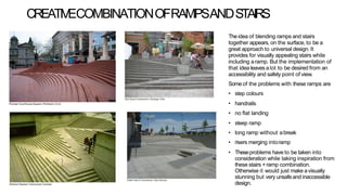
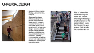
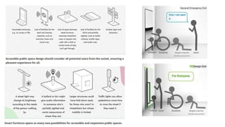


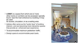
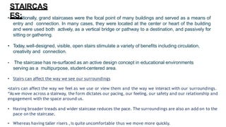
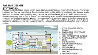
The document discusses comprehensive considerations for barrier-free design in buildings, focusing on elements such as lobbies, staircases, escalators, and elevators. It emphasizes the importance of design strategies that enhance accessibility and user experience, including natural lighting and ventilation, thermal comfort, and effective circulation. Additionally, it outlines various requirements and recommendations for ensuring safety, comfort, and energy efficiency in building design.


