Download to read offline
![STRUCTURAL ANALYSIS
OF A BUNGALOW
BUILDING STRUCTURES
[BLD61003]
PROJECT 2
Tay Jit Ying 0319002
Tan Wei Xin 0322731
Ng Yi Yang 0319688](https://image.slidesharecdn.com/finalstructurereport-161215124940/85/Final-structure-report-1-320.jpg)
![STRUCTURAL ANALYSIS
OF A BUNGALOW
BUILDING STRUCTURES
[BLD61003]
PROJECT 2
Tay Jit Ying 0319002
Tan Wei Xin 0322731
Ng Yi Yang 0319688](https://image.slidesharecdn.com/finalstructurereport-161215124940/75/Final-structure-report-1-2048.jpg)
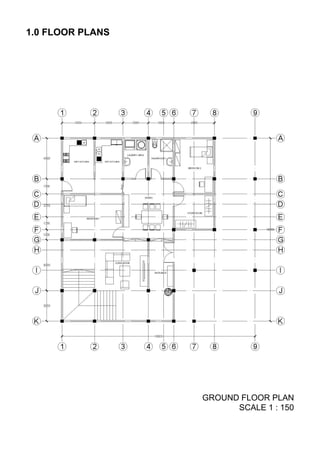
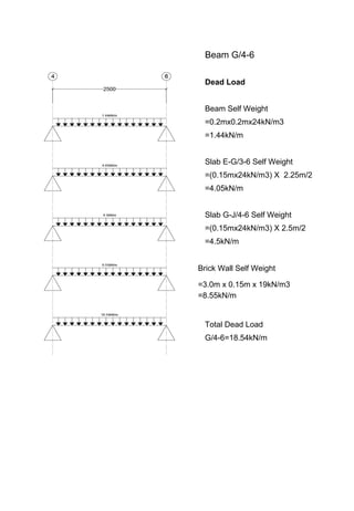
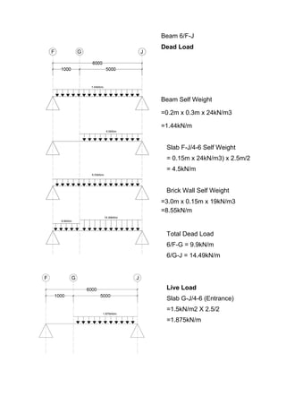
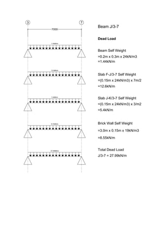
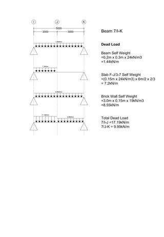
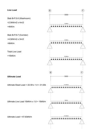
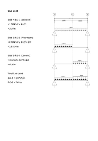
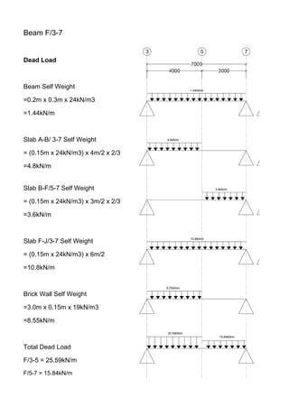
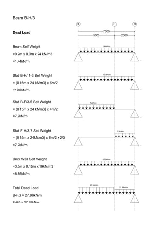
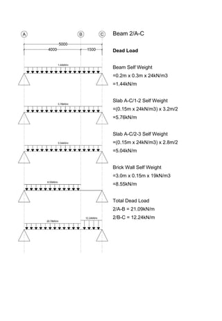
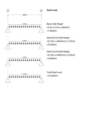
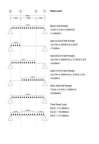
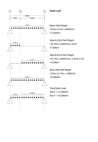
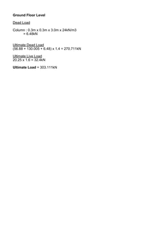
![Ground Floor Level
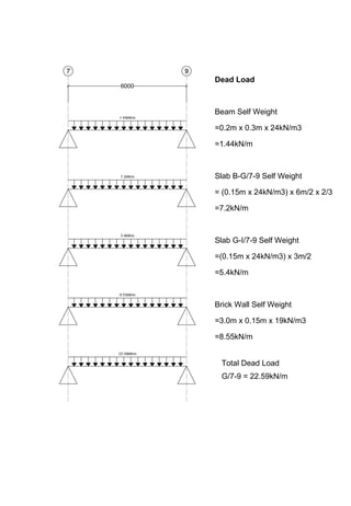
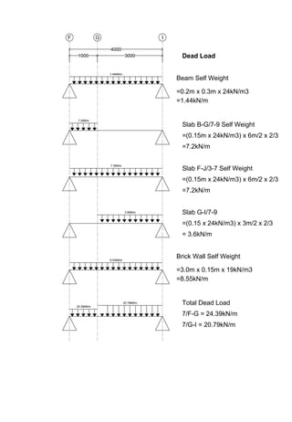
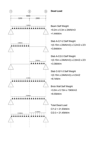
Dead Load
Walls: 7.1m x 8.55
= 60.705kN
Slabs: [1.6 x (0.75+1.25+1+2.5)] x 3.6 = 31.68kN
Beams: (0.75+1.25+1+2.5) + (1.6 x 1.44) = 10.224kN
Total : 109.089kN
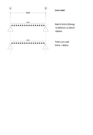
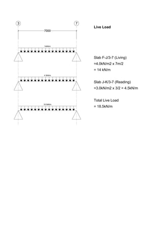
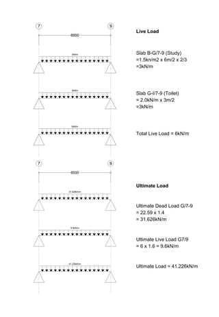
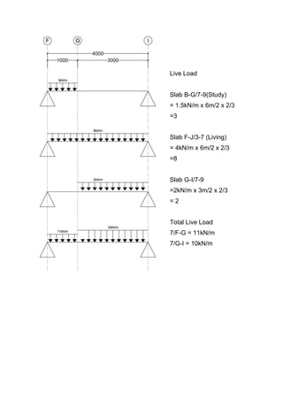
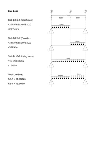
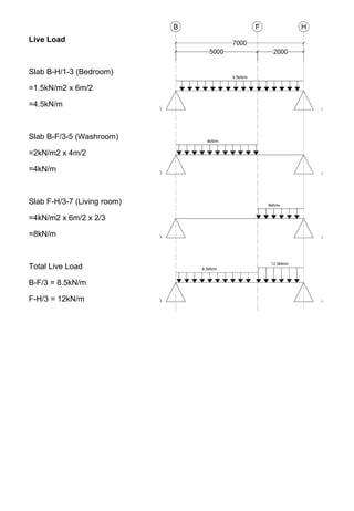
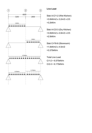
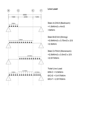
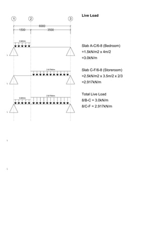
Live Load
Bedroom : 3 x 1.6 x 1.5 = 7.2kN
Corridor : (2.5 x 1.6) x 4 = 16kN
Total = 16 + 7.2
= 23.2kN
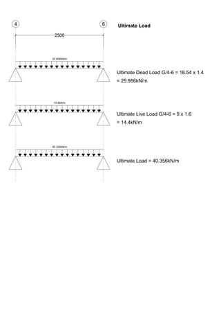
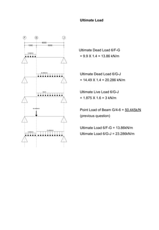
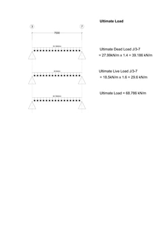
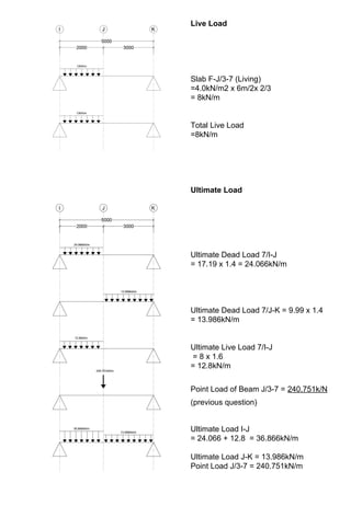
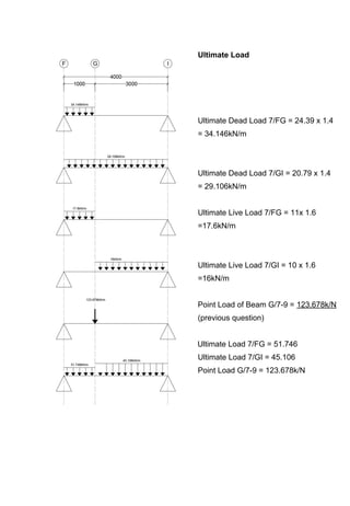
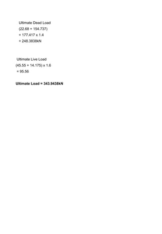
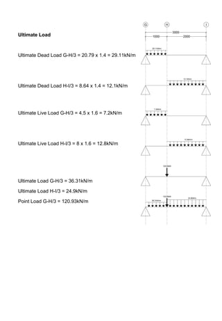
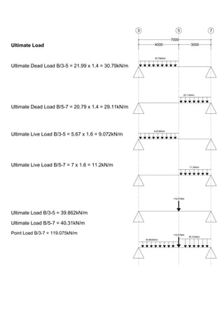
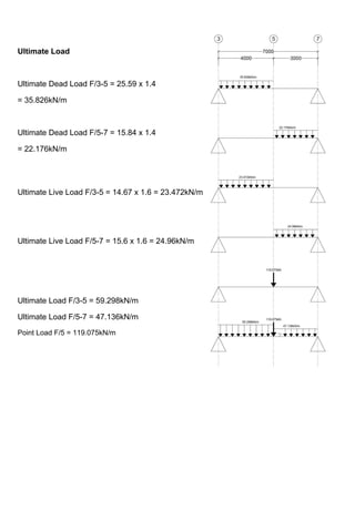
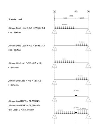
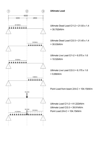
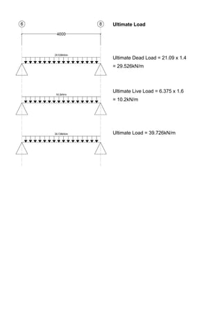
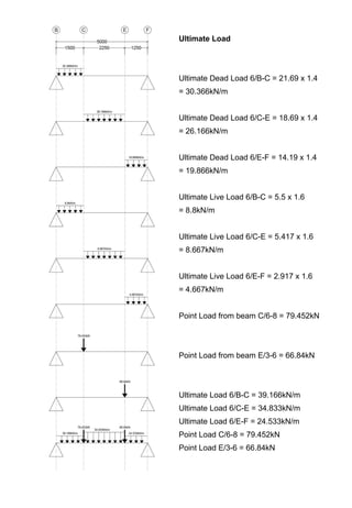
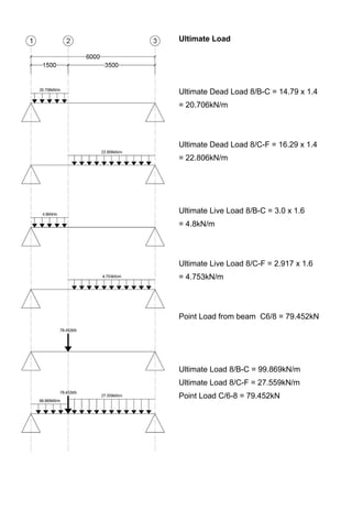
Ultimate Dead Load
(58.32+122.49+109.89) x 1.4 = 405.8586kN
Ultimate Live Load
(19.2 + 23.2 + 7.2) x 1.6 = 79.36
Ultimate Load = 405.8586 + 79.36 = 485.2186](https://image.slidesharecdn.com/finalstructurereport-161215124940/85/Final-structure-report-48-320.jpg)
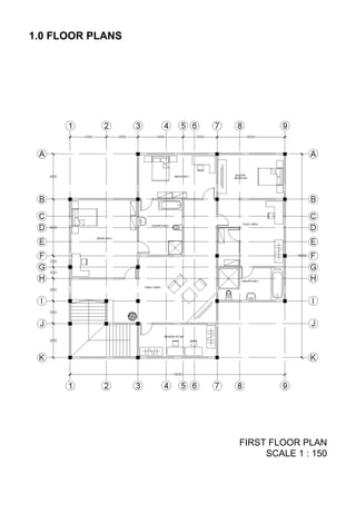
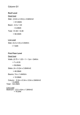
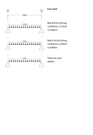
![Column G1
Ground Floor Level
Dead Load
Walls: 11.5m x 8.55kN/m
= 98.325kN
Slabs: (3.75 x 5.5)m x 3.6kN/m2
= 74.25kN
Beams: 11.5m x 1.44kN/m
= 16.56kN
Column: 0.3m x 0.3m x 3.0m x 24kN/m3
= 6.48kN
Total: 195.615kN
Live Load
Dining: [(0.75+1.25+1) x 2.5] x 2
= 15kN
Living: (2.5 x 2.5) x 4
=20kN
Entrance: (1.25 x 2.5) x 1.5
= 4.6875kN
Total: 39.6875kN
Ultimate Dead Load
195.615 x 1.4 = 273.861kN
Ultimate Live Load
39.6875 x 1.6 = 63.5
Ultimate Load = 337.361kN](https://image.slidesharecdn.com/finalstructurereport-161215124940/85/Final-structure-report-51-320.jpg)
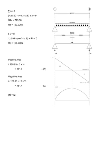
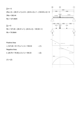
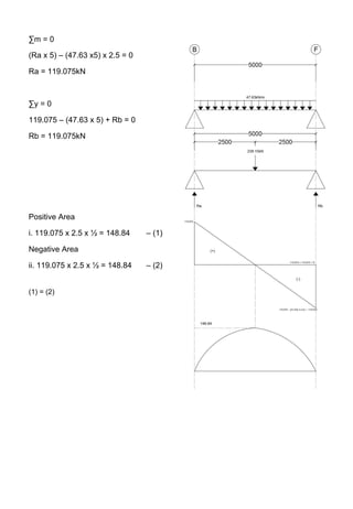
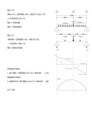
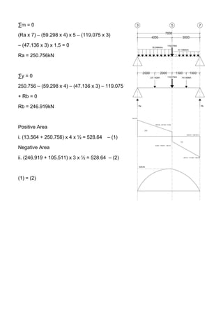
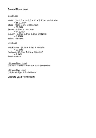
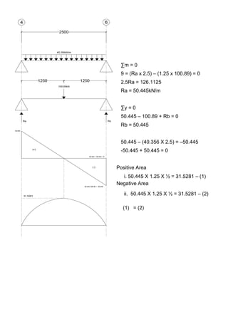
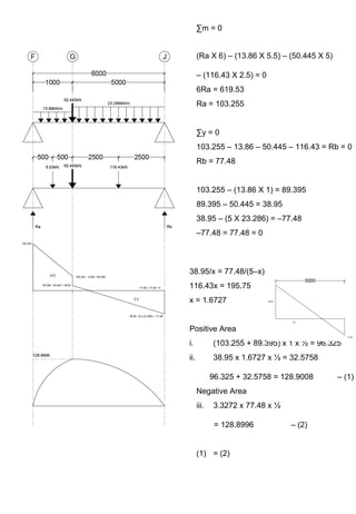
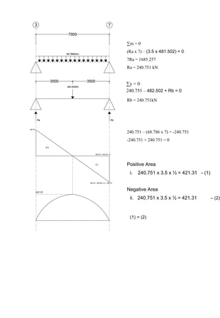
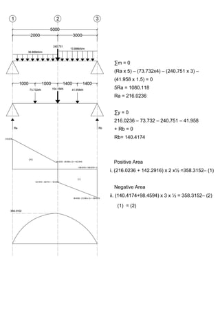
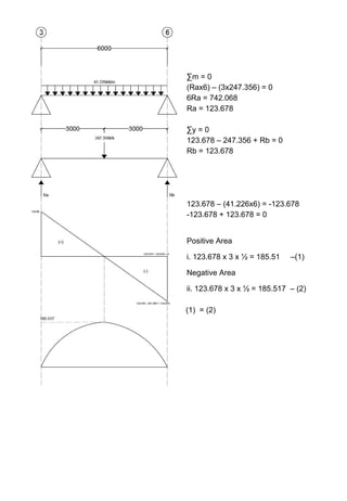
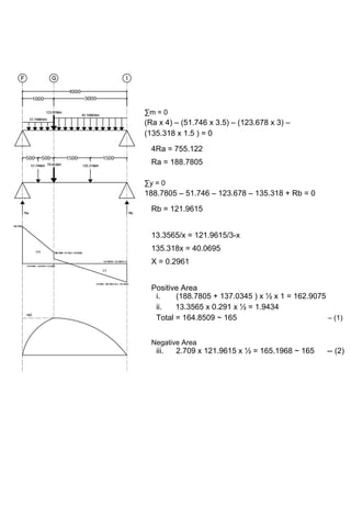
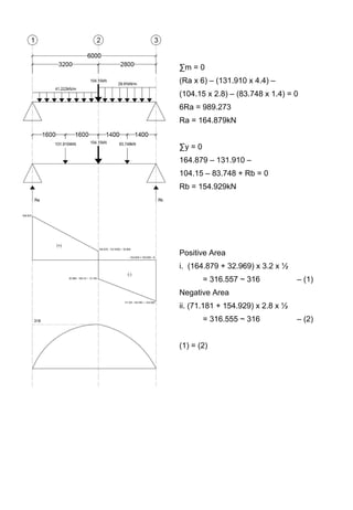
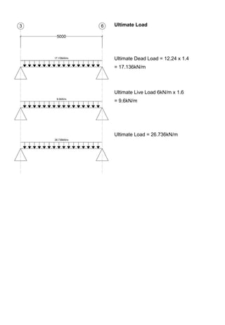
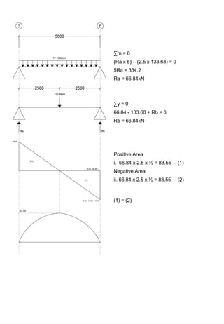
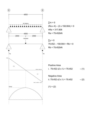
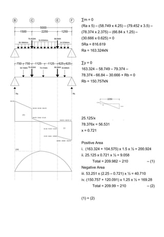
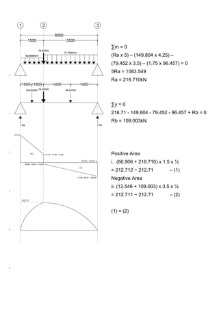
![∑m = 0
(Ra x 5.5) – (174.024 x 3.5) – (47.304 x 0.75)
= 0
5.5Ra = 644.478
Ra = 117.178kN
∑y = 0
117.178 – 174.024 – 47.304 + Rb = 0
Rb = 104.15kN
117.178/(4 - )x = 56.846/x
174.024x = 227.384
X = 1.307
Positive Area
i. (4.0 – 1.307) x 117.178 x ½
= 158 – (1)
Negative Area
ii. [ (1.307 x 56.846) x ½ ] +
[ (56.846 + 104.15) x 1.5 x ½
= 157.896 ~ 158 – (2)
(1) = (2)](https://image.slidesharecdn.com/finalstructurereport-161215124940/85/Final-structure-report-91-320.jpg)
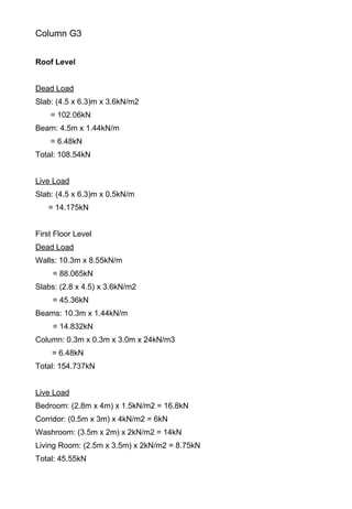
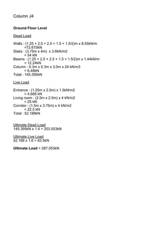
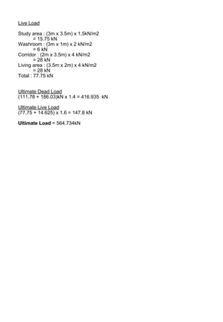
![Column B3
Roof Level
Dead Load
Slab : [ (6.3m x 5.0m) - (2.8m x 2.0m) ] x (0.15 x 24kN/m2)
= 93.24kN
Beam : 8.0m x 1.44kN/m
=11.52kN
Total : 104.76kN
Live Load
Slab : [ (6.3m x 5.0m) - (2.8m x 2.0m) ] x 0.5kN/m
= 12.95kN
First Floor Level
Dead Load
Walls : 11.5m x 8.55kN/m
=98.325kN
Slabs : (6.5m x 5m) x 3.6kN/m2)
= 117kN
Beams : 11.5m x 1.44kN/m
= 16.56kN
Column : 0.3m x 0.3m x 3.0m x 24kN/m3
= 6.48kN
Total : 238.365kN
Live Load
Bedroom : (3.5m x 2.0m) x 1.5kN/m2
= 10.5kN
Bedroom : (3.0m x 3.0m) x 1.5kN/m2
= 13.5kN
Toilet: (3.5m x 3m) x 2.0kN/m2
= 21kN
Total : 45kN](https://image.slidesharecdn.com/finalstructurereport-161215124940/85/Final-structure-report-117-320.jpg)
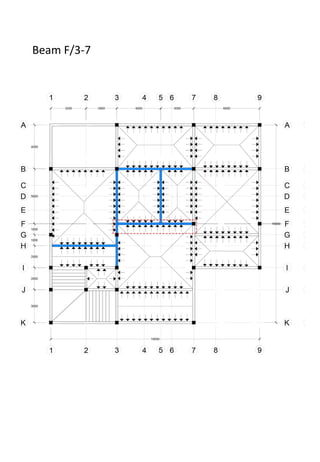
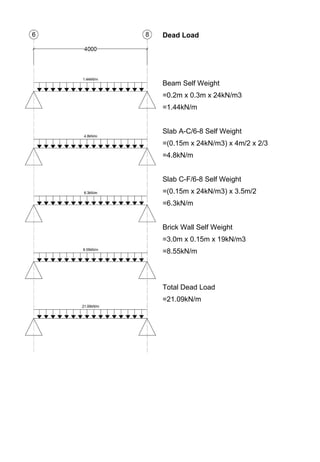
![Column F6
Ground Floor Level
Dead Load
Walls : 8.0m x 8.55kN/m
=68.4kN
Slabs : [ (3.25m x 6m) - (2.0m x 3.5m) ] x 3.6kN/m2)
= 45kN
Beams : 10.5m x 1.44kN/m
= 15.12kN
Column : 0.3m x 0.3m x 3.0m x 24kN/m3
= 6.48kN
Total : 135kN
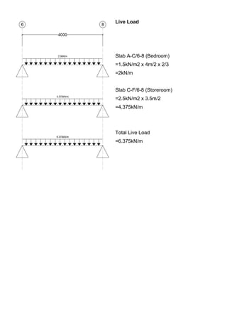
Live Load
Storeroom : (2.0m x 2.5m) x 1.5kN/m2
= 12.5kN
Dining : (1.25m x 2.25m) x 1.5kN/m2
= 5.625kN
Dining : (1.25m x 1.25m) x 1.5kN/m2
= 3.125kN
Entrance : (1.25m x 2.5m) x 1.5kN/m2
= 4.6875
Total : 25.933kN
Ultimate Dead Load
135kN x 1.4 = 189kN
Ultimate Live Load
25.9325 x 1.6 = 41.492kN
Ultimate Load = 230.492kN](https://image.slidesharecdn.com/finalstructurereport-161215124940/85/Final-structure-report-119-320.jpg)

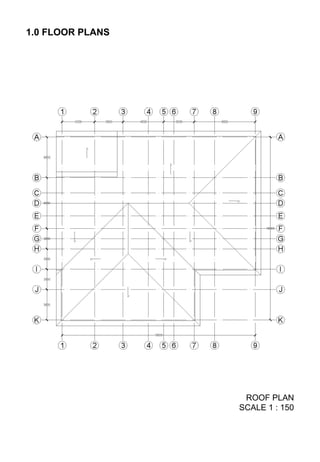
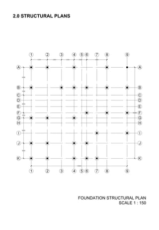
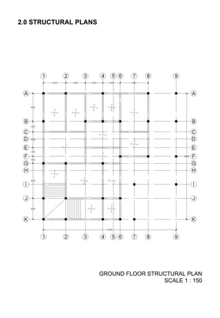
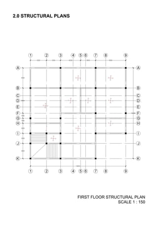
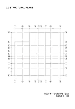
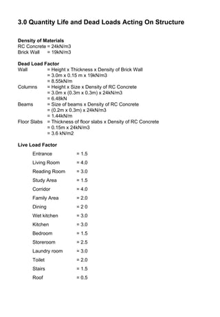
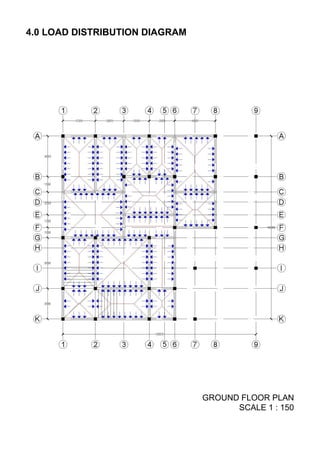
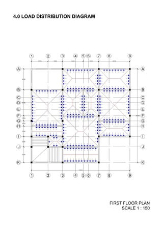
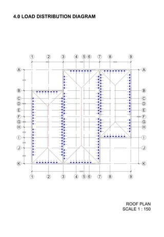
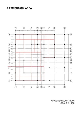
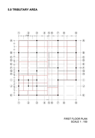
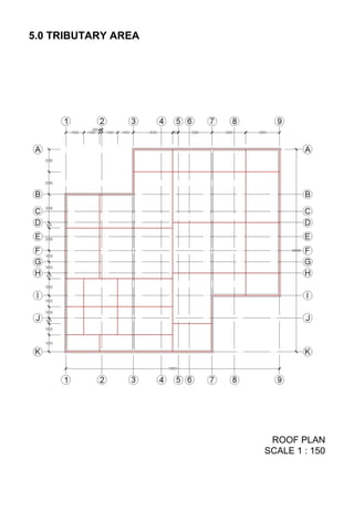
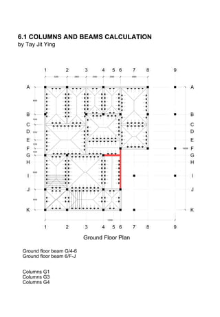
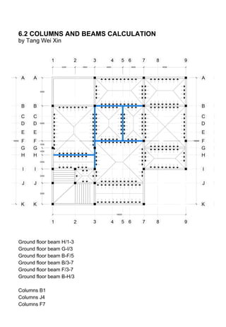
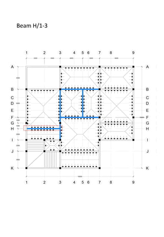
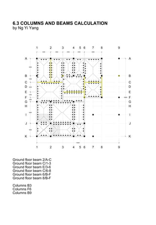
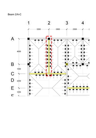
This document provides details on the structural analysis of a double storey bungalow building. It includes floor plans, structural plans, load calculations, load distribution diagrams, and tributary area calculations. Dead and live loads acting on the structure are quantified. Beam and column calculations are presented for key structural elements, including determination of ultimate loads and checking of moment and shear forces. The analysis aids in understanding the building structure and ensuring safety under different loads and forces.


