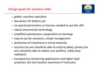
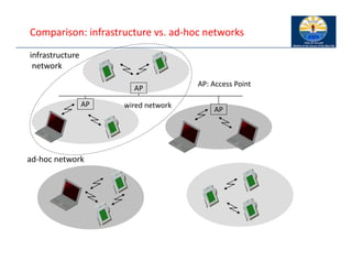
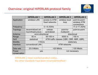
The document provides an overview of wireless LANs, including their characteristics, standards like IEEE 802.11, and comparison between infrastructure and ad-hoc networks. It discusses the advantages and disadvantages of wireless LANs, design goals, and various IEEE standards and their developments for improving data rates, security, and network management. Specific features, layers, and functions of the 802.11 architecture, along with future developments and comparisons to HIPERLAN standards, are also covered.

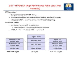
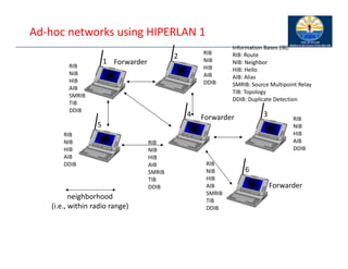
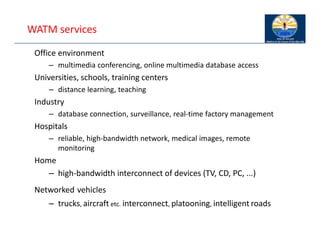
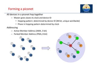
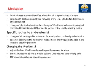
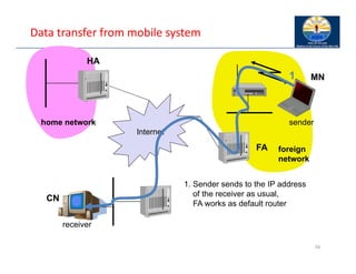
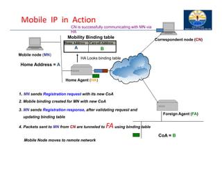
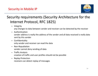
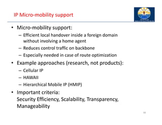
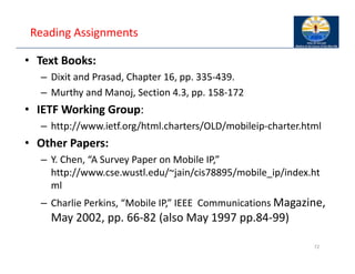
![Information bases
Route Information Base (RIB) ‐ how to reach a destination
– [destination, next hop, distance]
Neighbor Information Base (NIB) ‐ status of direct neighbors
– [neighbor, status]
Hello Information Base (HIB) ‐ status of destination (via next hop)
– [destination, status, next hop]
Alias Information Base (AIB) ‐ address of nodes outside the net
– [original MSAP address, alias MSAP address]
Source Multipoint Relay Information Base (SMRIB) ‐ current MP
status
– [local multipoint forwarder, multipoint relay set]
Topology Information Base (TIB) ‐ current HIPERLAN topology
– [destination, forwarder, sequence]
Duplicate Detection Information Base (DDIB) ‐ remove
duplicates
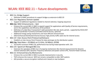
– [source, sequence]](https://image.slidesharecdn.com/6-250115063759-6c4ea2ff/85/6-WLAN-annd-7__________-Mobile-IP-pdf-34-320.jpg)
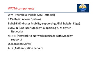
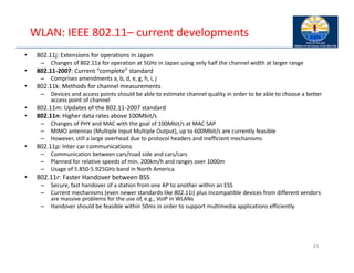
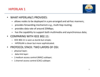
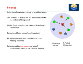
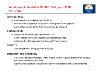
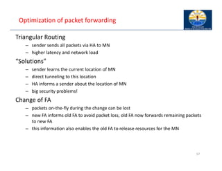
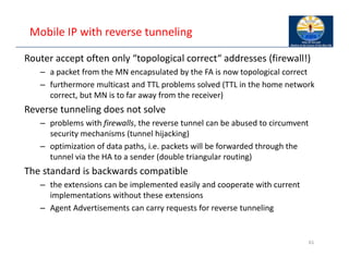
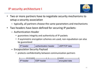
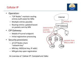
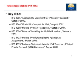
![Bluetooth
History
– 1994: Ericsson (Mattison/Haartsen), “MC‐link” project
– Renaming of the project: Bluetooth according to Harald “Blåtand” Gormsen [son of
Gorm], King of Denmark in the 10th century
– 1998: foundation of Bluetooth SIG, www.bluetooth.org
– 1999: erection of a rune stone at Ercisson/Lund ;‐)
– 2001: first consumer products for mass market, spec. version 1.1 released
Special Interest Group
– Original founding members: Ericsson, Intel, IBM, Nokia, Toshiba
– Added promoters: 3Com, Agere (was: Lucent), Microsoft, Motorola
– > 2500 members
– Common specification and certification of products
(was: )](https://image.slidesharecdn.com/6-250115063759-6c4ea2ff/85/6-WLAN-annd-7__________-Mobile-IP-pdf-41-320.jpg)


![802.11[1]](https://cdn.slidesharecdn.com/ss_thumbnails/802-140414140943-phpapp02-thumbnail.jpg?width=640&height=640&fit=bounds)


