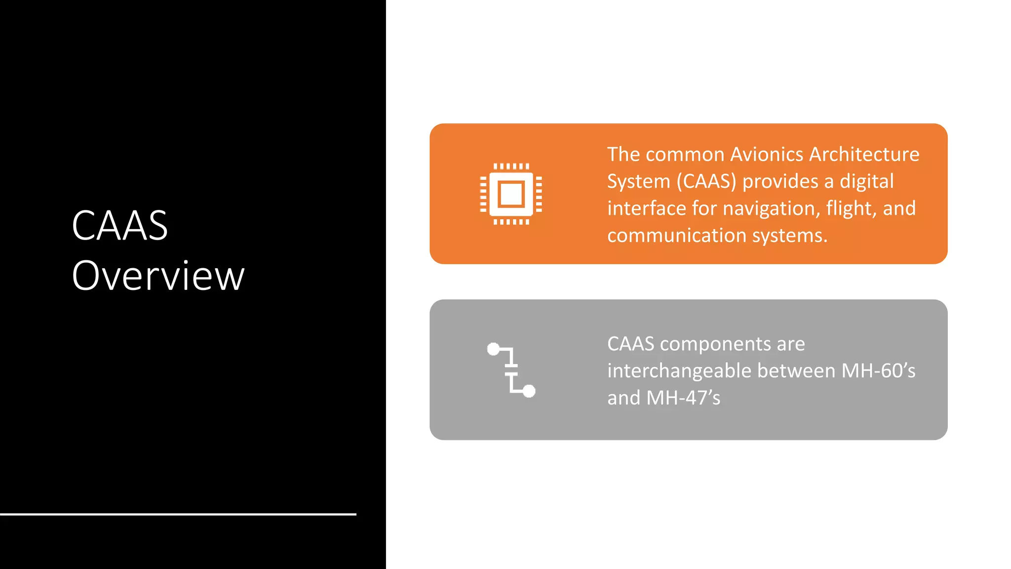
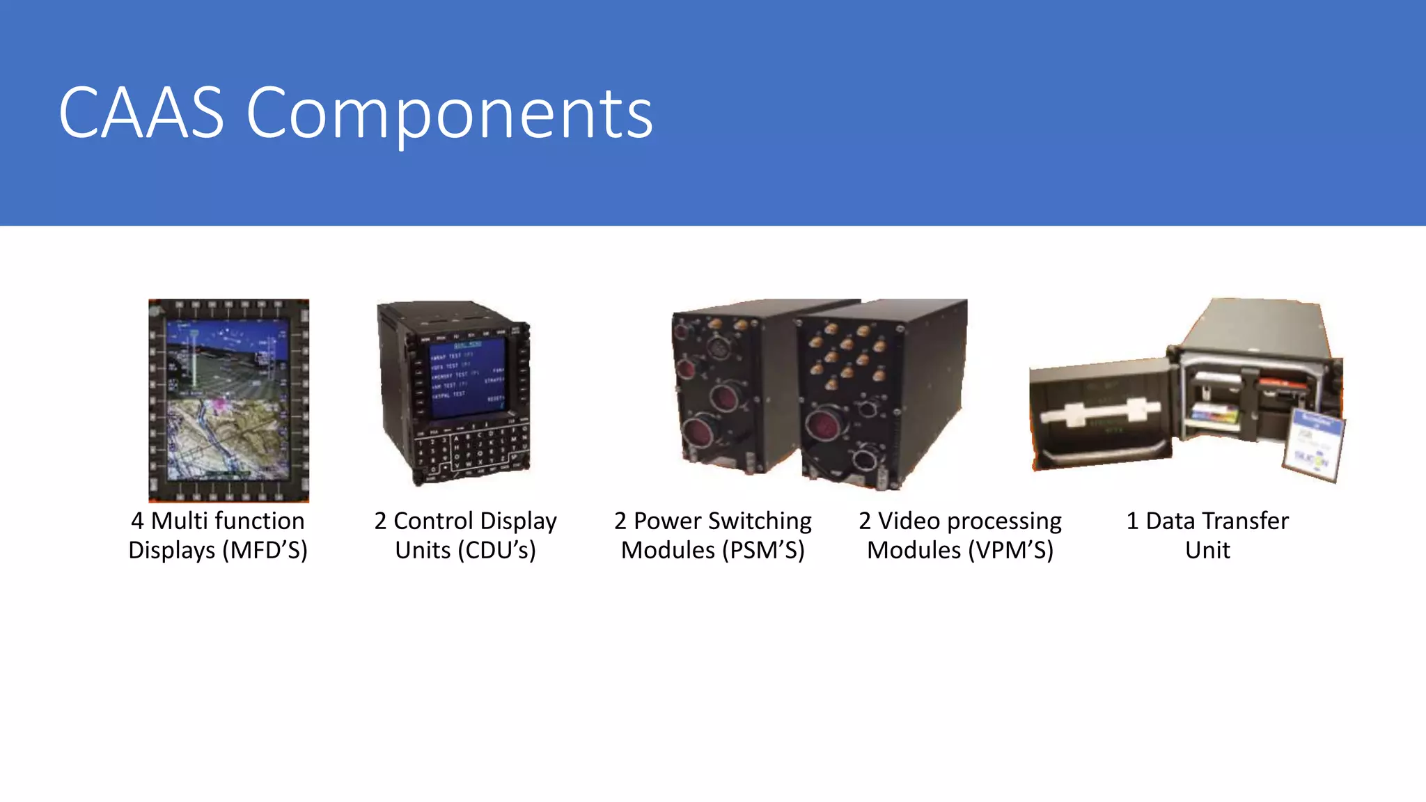
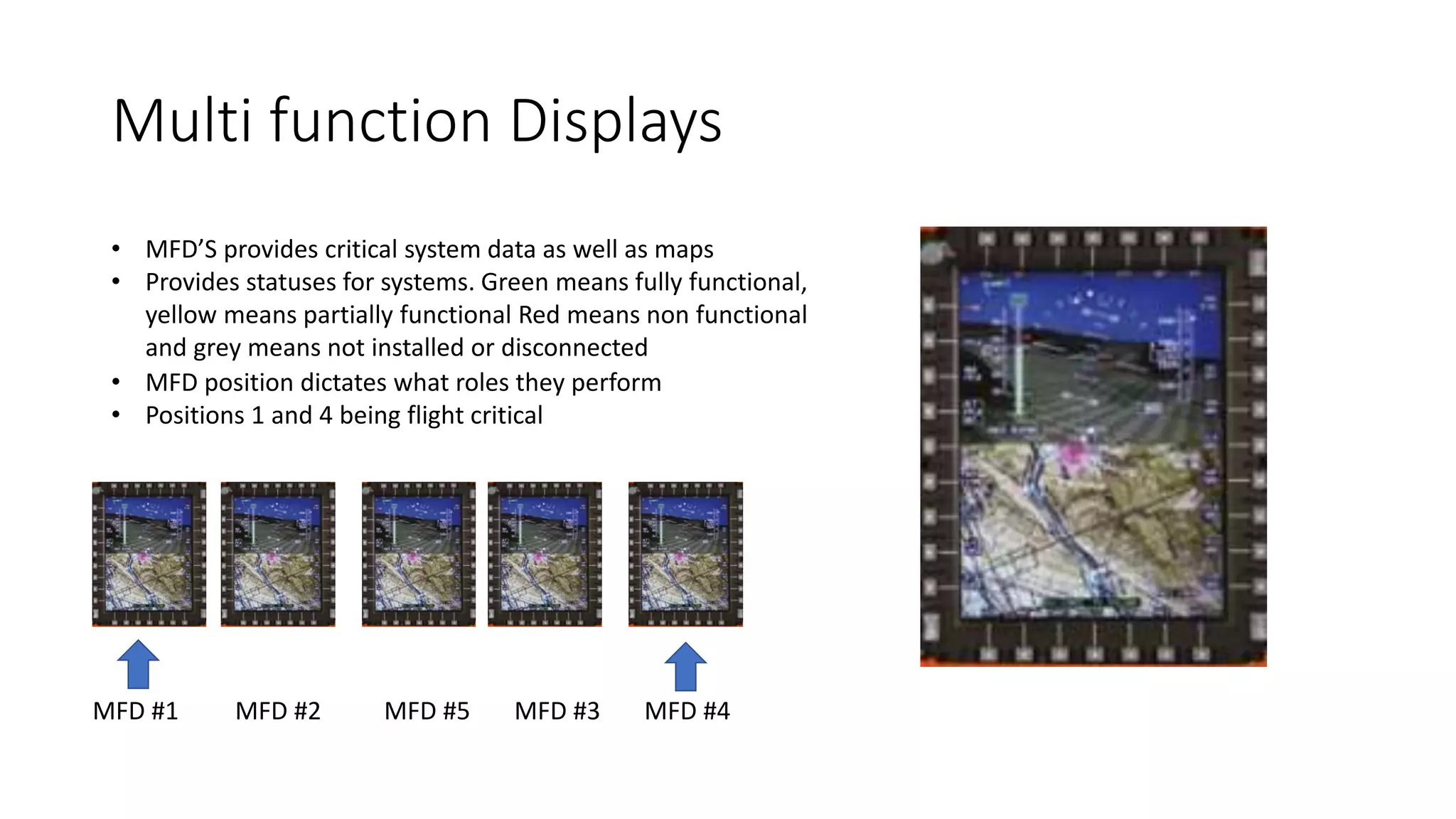
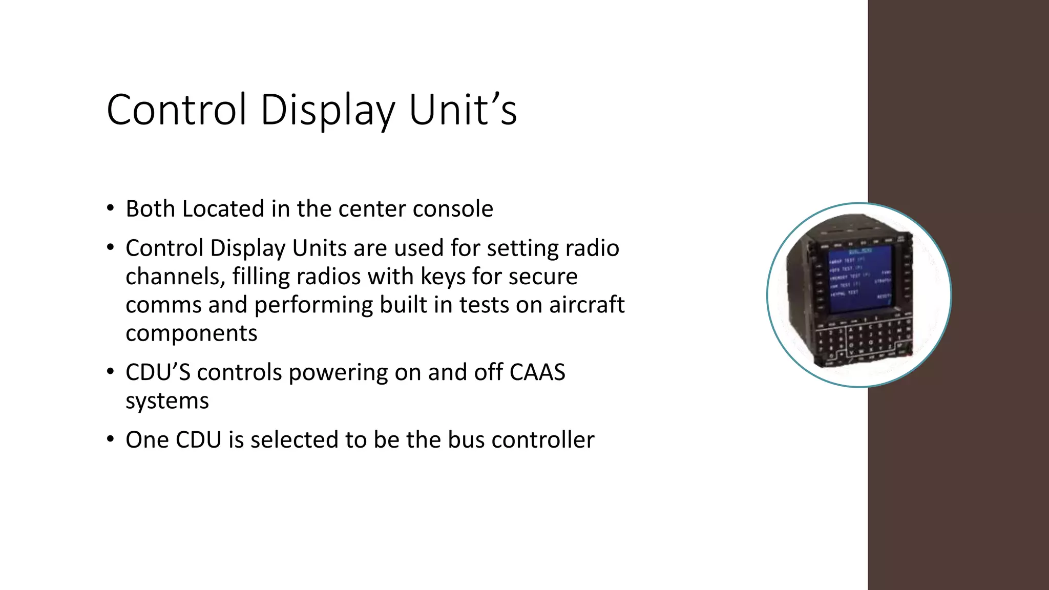
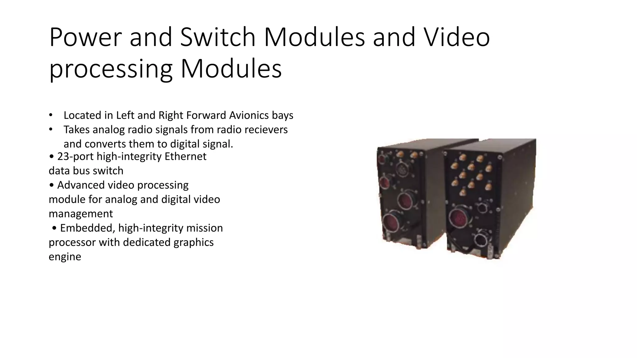
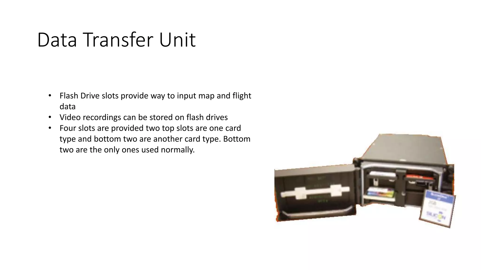
Common Avionic
Architecture System
By Austin Hanika
CAAS
Overview
The common Avionics Architecture
System (CAAS) provides a digital
interface for navigation, flight, and
communication systems.
CAAS components are
interchangeable between MH-60’s
and MH-47’s
CAAS Components
4 Multi function
Displays (MFD’S)
2 Control Display
Units (CDU’s)
2 Power Switching
Modules (PSM’S)
2 Video processing
Modules (VPM’S)
1 Data Transfer
Unit
Multi function Displays
• MFD’S provides critical system data as well as maps
• Provides statuses for systems. Green means fully functional,
yellow means partially functional Red means non functional
and grey means not installed or disconnected
• MFD position dictates what roles they perform
• Positions 1 and 4 being flight critical
MFD #1 MFD #2 MFD #5 MFD #3 MFD #4
Control Display Unit’s
• Both Located in the center console
• Control Display Units are used for setting radio
channels, filling radios with keys for secure
comms and performing built in tests on aircraft
components
• CDU’S controls powering on and off CAAS
systems
• One CDU is selected to be the bus controller
Power and Switch Modules and Video
processing Modules
• Located in Left and Right Forward Avionics bays
• Takes analog radio signals from radio recievers
and converts them to digital signal.
• 23-port high-integrity Ethernet
data bus switch
• Advanced video processing
module for analog and digital video
management
• Embedded, high-integrity mission
processor with dedicated graphics
engine
Data Transfer Unit
• Flash Drive slots provide way to input map and flight
data
• Video recordings can be stored on flash drives
• Four slots are provided two top slots are one card
type and bottom two are another card type. Bottom
two are the only ones used normally.
CAAS connections
• MIL-STD-1553 is the military standard
serial data bus used in military Avionics
• Data bus couplers (shown to the right)
provide connections for several serial
lines that go to the same area
• Terminators (shown below) provide end
points for the signals to stop at

Avionics class

  • 1.
  • 2.
    CAAS Overview The common AvionicsArchitecture System (CAAS) provides a digital interface for navigation, flight, and communication systems. CAAS components are interchangeable between MH-60’s and MH-47’s
  • 3.
    CAAS Components 4 Multifunction Displays (MFD’S) 2 Control Display Units (CDU’s) 2 Power Switching Modules (PSM’S) 2 Video processing Modules (VPM’S) 1 Data Transfer Unit
  • 4.
    Multi function Displays •MFD’S provides critical system data as well as maps • Provides statuses for systems. Green means fully functional, yellow means partially functional Red means non functional and grey means not installed or disconnected • MFD position dictates what roles they perform • Positions 1 and 4 being flight critical MFD #1 MFD #2 MFD #5 MFD #3 MFD #4
  • 5.
    Control Display Unit’s •Both Located in the center console • Control Display Units are used for setting radio channels, filling radios with keys for secure comms and performing built in tests on aircraft components • CDU’S controls powering on and off CAAS systems • One CDU is selected to be the bus controller
  • 6.
    Power and SwitchModules and Video processing Modules • Located in Left and Right Forward Avionics bays • Takes analog radio signals from radio recievers and converts them to digital signal. • 23-port high-integrity Ethernet data bus switch • Advanced video processing module for analog and digital video management • Embedded, high-integrity mission processor with dedicated graphics engine
  • 7.
    Data Transfer Unit •Flash Drive slots provide way to input map and flight data • Video recordings can be stored on flash drives • Four slots are provided two top slots are one card type and bottom two are another card type. Bottom two are the only ones used normally.
  • 8.
    CAAS connections • MIL-STD-1553is the military standard serial data bus used in military Avionics • Data bus couplers (shown to the right) provide connections for several serial lines that go to the same area • Terminators (shown below) provide end points for the signals to stop at