Download to read offline
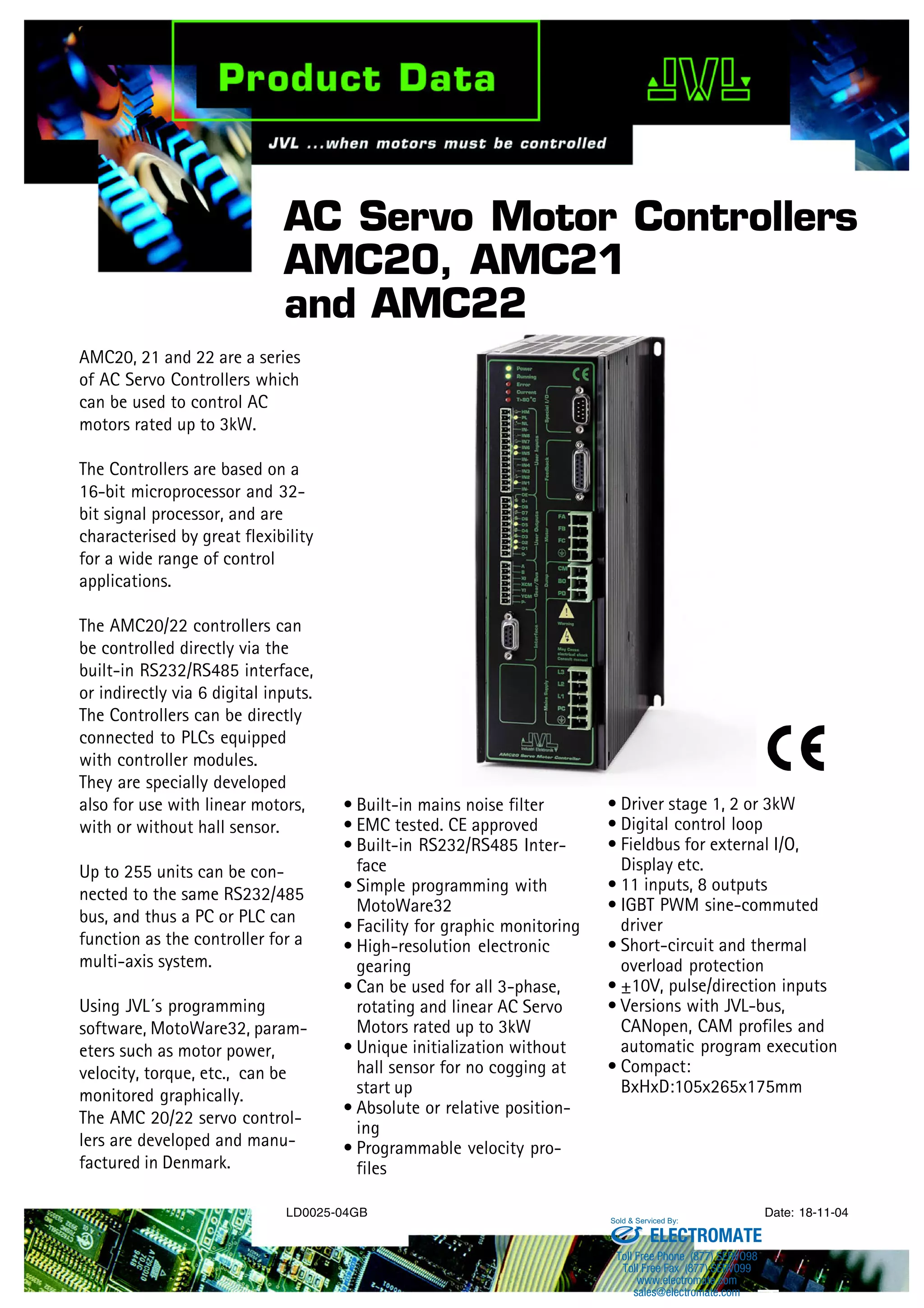
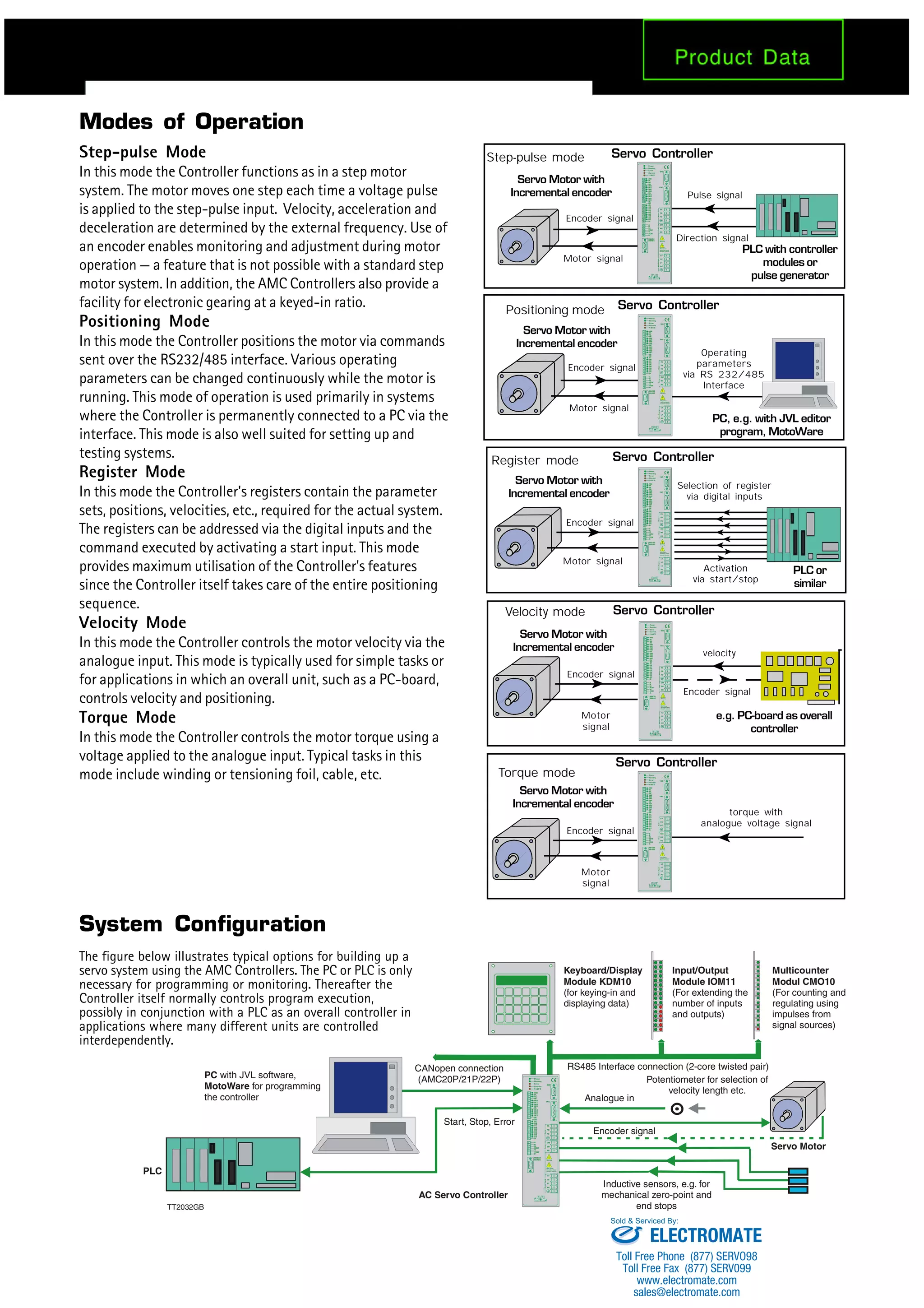

The document describes AC servo motor controllers AMC20, AMC21, and AMC22. The controllers can be used to control AC motors up to 3kW. They have digital and analog inputs and outputs and integrated RS232/RS485 interfaces for communication. They can operate in different modes including step-pulse, positioning, register, velocity, and torque control modes. The controllers are programmed using MotoWare32 software and can control single or multi-axis servo systems.


![Coded Agents – with UiPath SDK + LangGraph [Virtual Hands-on Workshop]](https://cdn.slidesharecdn.com/ss_thumbnails/codedagentsdeck-251215155422-5497c599-thumbnail.jpg?width=640&height=640&fit=bounds)


