Downloaded 62 times
![Abstract— This paper describes the hardware and software system integration process for an Integrated
Modular Avionics(IMA) architecture of aircraft involving ARINC 653 and ARINC 664 avionics protocols.
Index Terms— Avionics, Integrated Modular Avionics(IMA), ARINC 653,ARINC 664
1. Introduction
The concept of integrated modular avionics came due to the huge advancements in the electronics industry,
increased functional complexity in the avionics systems and need for smart integrated and modular systems. The
concept of integrated modular avionics came in mid 90's due to huge investments made by the airline industries
on more integrated platforms. The basic concept behind IMA is sharing the common set of “cabinets” with
ARINC 653 specifications that are connected simultaneously with other secondary equipment through number
of multiple access network which are based on ARINC 664 specifications. Each cabinet is a high-power
computing hub which substitutes a number of avionics applications. Each cabinet has an adequate processing
and interface capability to maintain the required integration of avionics functionality. The system specific
application software is designed to conform the appropriate standards of the application executive interface
specification (APEX). Thus this application standard also allows the application software reusability on
processors of diverse hardware designs.
2. ARINC 653 and ARINC 664
ARINC 653 is an industry specification originating from the civil aviation industry. It defines the partitioning of
software and addresses these issues. Software partitioning is an important topic, but this methodology has also
helped to address other important issues that had proved very difficult to overcome in the past, including the
obsolescence of hardware. The obsolescence of hardware has always been a grave dilemma for avionics
industry but has been greatly reduced by the adoption of Commercial off the Shelf(COTS) technology. The
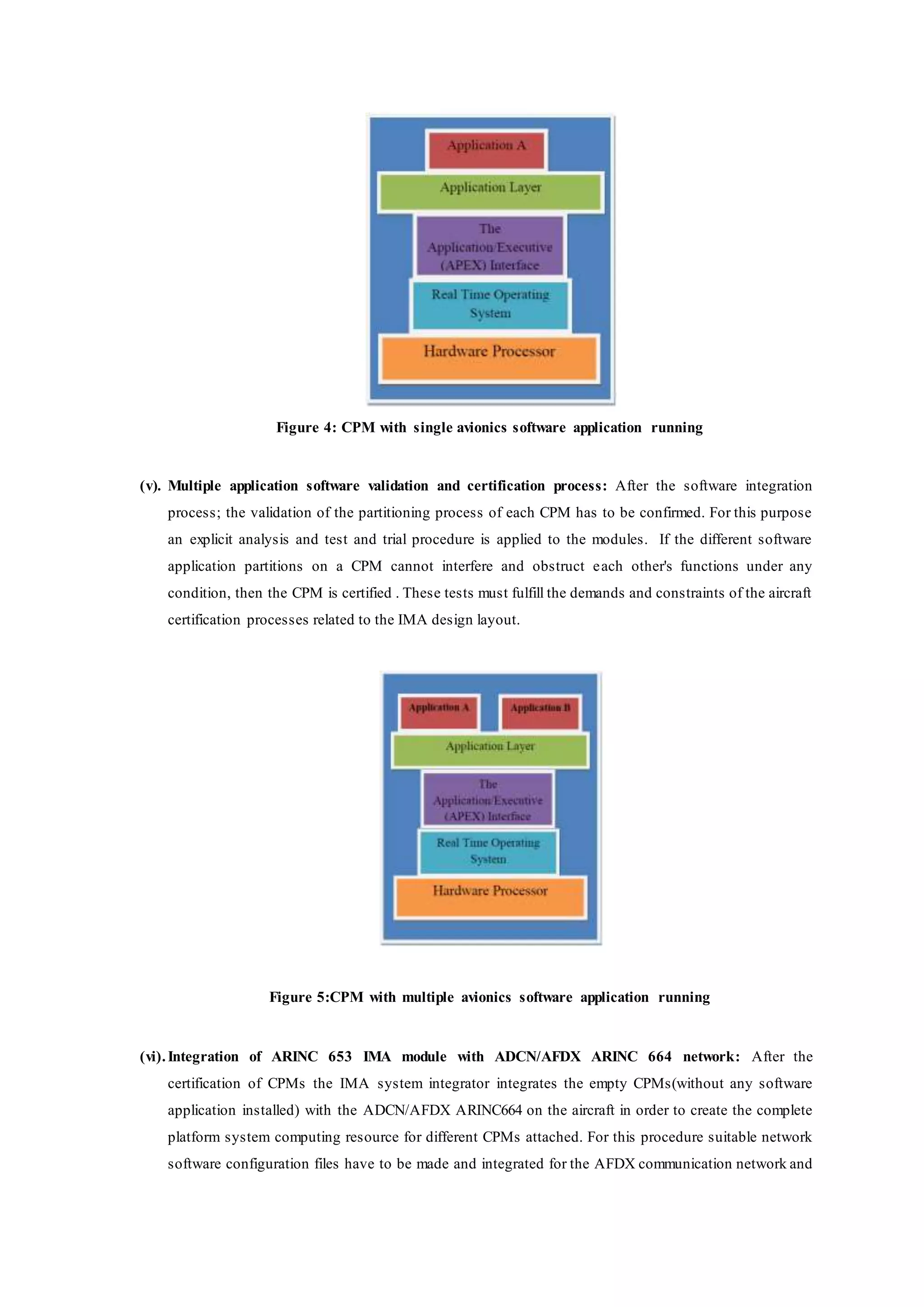
ARINC 653 philosophy has a layered approach shown in the figure 1. These layers provide the following:
(a) At the top level, an ARINC 653 compliant software infrastructure or application programming
interface (API) provides the partitioning of avionics systems functions that are developed specifically
for the platform.
(b) The API infrastructure interfaces with the RTOS which will generally be a commercial package. In
many cases the RTOS will be DO-178B compliant.[4]
(c) A board support package will provide the necessary software support to enable the COTS hardware to
interface with the commercial RTOS and API layers.
(d) The hardware layer based upon COTS expertise will be the most vibrant and rapidly varying
component of this architectural implementation. The decoupling of the hardware processor from the
application software means that the hardware obsolescence can be contained and technology advances
can be enjoyed while the investment in software applications and systemfunctionality is protected.[4]](https://image.slidesharecdn.com/integratedmodularavionicimasystemintegrationprocess-150713065855-lva1-app6891/75/Integrated-Modular-Avionic-IMA-System-Integration-Process-1-2048.jpg)
![Figure 1: Layered approach of the Cabinet module using ARINC 653 specifications
The “AFDX” standard is the Part 7[1][2] of the ARINC-664 “Aircraft Data Network” standard, called “Avionics
Full Duplex Switched Ethernet Network” introduced formally in 2005. It describes a “more deterministic”
switched Ethernet/IP network.
3. The IMA system integration process
The aim of this integration procedure is to get the majority of the aircraft system level tasks and functions
which are being operated on standardized IMA platforms and connect themto the Aircraft Data Communication
Network (ADCN) which is primarily based on the Aeronautical Full Duplex (100Mbit AFDX)[1][3] switched
Ethernet state of art technology.
For the manufacturing and integration of the IMA system in an aircraft platform there are several suppliers,
manufacturers and contractors which are associated during the whole process.
Following are the responsibilities defined for each contractor:
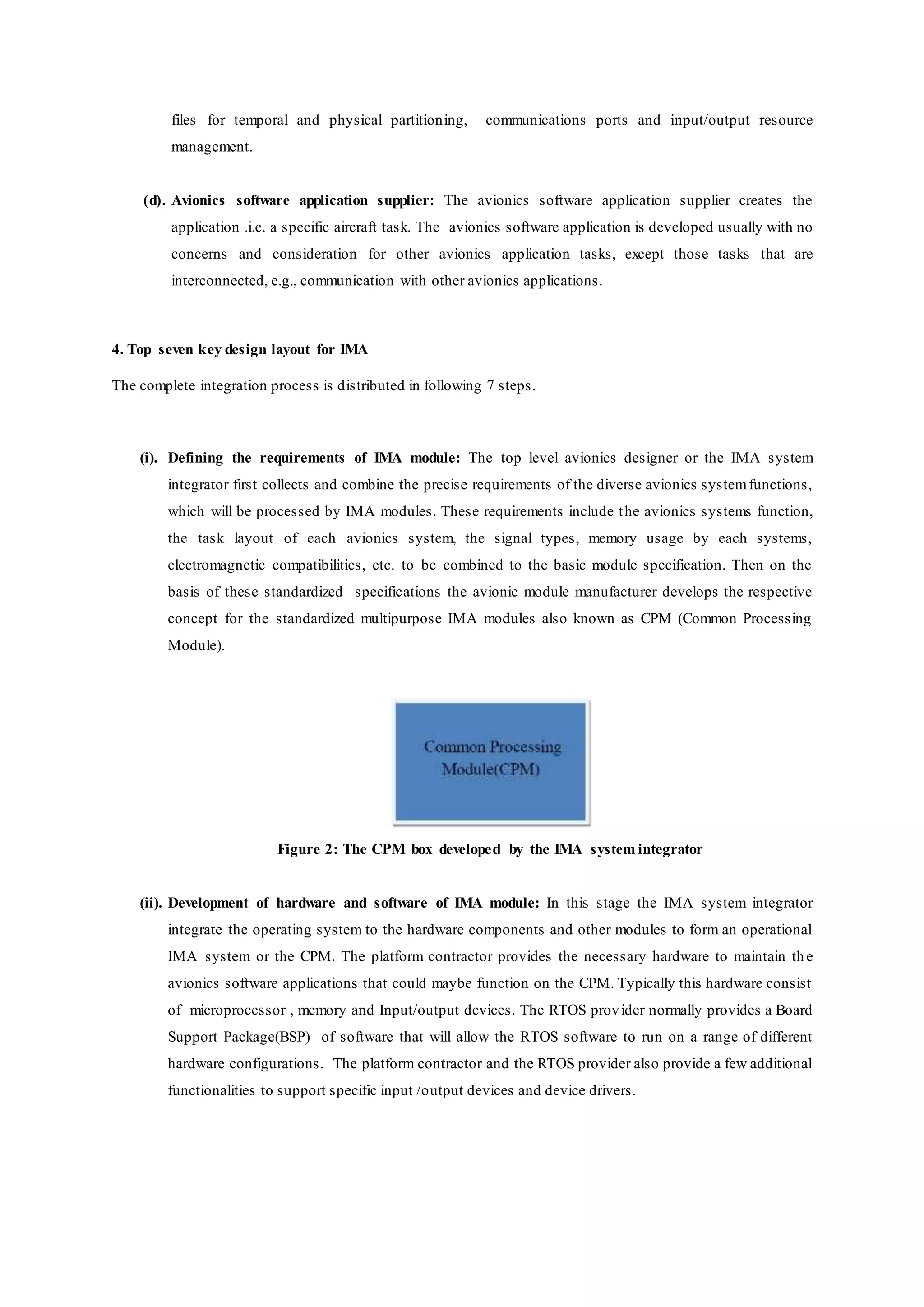
(a). The IMA system integrator: The IMA system integrator performs the complete integration in all the
stages of the assimilation process. The IMA system integrator must deal with all interfaces linked with
the IMA system configuration. He has to deal with the each selected avionics applications to be
hosted. He has to provide the memory resource allocation, configuration files and tables adjustments
and in general validating the performance of the integrated system
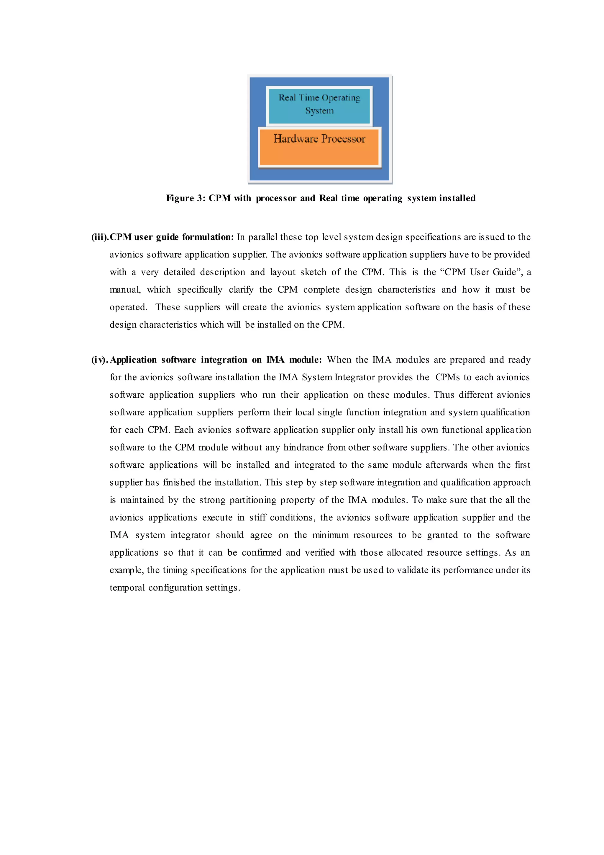
(b). Platform contractor: The platform contractor supply the processing hardware resources with the core
software(Operating system). The operating system also includes interfacing software that links the
hardware components with the operating system.
(c). The RTOS provider: The RTOS provider identify the hardware aspects of the IMA systems and
convey them to the platform contractor. The RTOS provider supply the guidelines and configuration](https://image.slidesharecdn.com/integratedmodularavionicimasystemintegrationprocess-150713065855-lva1-app6891/75/Integrated-Modular-Avionic-IMA-System-Integration-Process-2-2048.jpg)
![for the CPM operation. The networks are primarily based on copper-cabling but fiber optics will be
utilized in future.[2] This integration requires two main configurations.
a) The AFDX/ADCN ARINC664 configuration primarily concerns the address tables of the
Ethernet switches, the data frame size of each virtual link(VL),the bandwidth allocation gap
values(BAG) and the required bandwidth of the virtual links (VL).
b) The configuration process of the CPM includes the allocation of memory space to each
software application, signal ports designations(the queuing and sampling ports) and
processing cycle time layout designations to the different application SW partitions. This
configuration data is arranged in configuration files, which are loaded on the CPM in order to
get the operating system perform as required by the different Software applications that are
being executed on each module.
Figure 6: The integrated network: The colored (Red, yellow, blue) arrows shows the virtual links
(vii). Installation of CPMs and configuration tables on aircraft: After completion of the local
functional qualification test and certification ; the system software manufacturers provide their
respective application software partitions to the IMA system integrator which adds the respective
configuration tables to each partition and then the qualification test procedures are being executed to
certify that the complete integrated system is been working perfectly. Thus, finally the application
software partitions and the configuration files make up the final software load that is delivered to th e
final assembly line where it is loaded to the empty CPMs on the aircraft under production.
5. Conclusion
The key 7 design layout can provide a great advantage in the integration of modular avionics for any
type of aircraft program. The level of system integration and openness of the avionics platformfor any
particular aircraft type, will based mainly upon the aircraft manufacturer.
AFDX implementations still remain relatively conservative, using a proven and mature technology
base instead of state-of- the-art hardware. For example, the Airbus A380’s and A350’s networks are](https://image.slidesharecdn.com/integratedmodularavionicimasystemintegrationprocess-150713065855-lva1-app6891/75/Integrated-Modular-Avionic-IMA-System-Integration-Process-6-2048.jpg)
![based on copper-cabling, while optical cabling has become the de-facto standard for high speed
interconnection on backbones in corporate and carrier backbones. However, ARINC 664 architectures
can integrate future technology seamlessly. Future AFDX implementations like the one used in
Boeing’s 787 will use fiber optics[2]
Within ARINC 653 the module architecture has influence on the working of RTOS and its execution,
however it does not have any effect on the APEX interface which is used by the application software of
each partition. The application software must be portable between modules without modifying its
interface with the RTOS.
As the aircraft systems are developing into more and more digital systems through the utilization of
smart and small peripheral devices and remote data sensors, the requirement of analogue and discrete
input/output interface links within computing platforms will diminish.
Thus the future that is expected from IMA is the use of multiple application types running on a
computing module, where each module hosting variety of avionics system applications with smart
peripherals and they are networked together by means of high-speed data buses such as A664.](https://image.slidesharecdn.com/integratedmodularavionicimasystemintegrationprocess-150713065855-lva1-app6891/75/Integrated-Modular-Avionic-IMA-System-Integration-Process-7-2048.jpg)
![REFERENCES
[1] "Architecting ARINC 664, Part 7 (AFDX) Solutions" by Ian Land and Jeff Elliott XAPP1130 (v1.0.1)
May 22, 2009
[2] "The Evolution of Avionics Networks From ARINC 429 to AFDX" by Christian M. Fuchs Advisors:
Stefan Schneele, Alexander Klein at Seminar Aerospace Networks SS2012; Chair for Network
Architectures and Services August 2012,Faculty of Informatics, Technical University of Munich
[3] "AFDX/ARINC 664 Concept, Design, Implementation and Beyond" By Detlev Schaadt, CTO, SYSGO
AG
[4] "Military Avionics Systems" by Ian Moir and Allan Seabridge.
[5] "Civil Avionics Systems" by Ian Moir and Allan Seabridge
[6] "Introduction to Avionics Systems" by R.P.G Collinson.
[7] "ARINC 653 role in integrated modular avionic(IMA") Paul J. Prisaznuk, AEEC staff, ARINC,
Annapolis, Maryland, 2008 IEEE.
[8] "Civil aircraft advanced avionics architectures – an insight into saras avionics, present and future
perspective" CM Ananda Aerospace Electronics Systems Division National Aerospace Laboratories
[9] "Communications for Integrated Modular Avionics" by Richard L. Alena Richard.L.Alena@nasa.gov ,
John P. Ossenfort IV, SAIC ,Kenneth I. Laws, QSS Andre Goforth NASA Ames Research Center
Moffett Field, CA 94035 Fernando Figueroa, NASA Stennis Space Center
[10] "Open Integrated Modular Avionic (IMA): State of the Art and future Development Road Map" at
Airbus Deutschland by Henning Butz ; Department of Avionic Systems at Airbus Deutschland GmbH
Kreetslag 10, D-21129 Hamburg, Germany
[11] "Integrated Modular Avionics with COTS directed to Open Systems and Obsolescence Management"
by G. Grabowski, B. Balser, M. Frster(January 2001) European Aeronautic Defence and Space
Deutschland GmbH P.O. Box 80 11 09 81663 Mdinchen Germany
[12] "Integrated Modular Avionics Development Guidance and Certification Considerations " by René L.C.
Eveleens National Aerospace Laboratory NLR P.O. Box 90502 1006BM Amsterdam Netherlands
[13] "High level failure analysis for Integrated ModularAvionics" by Philippa Conmy, John McDermid
Department of Computer Science, University of York, York, YO10 5DD, U.K.
[14] "Open Systems Integrated Modular Avionics – The Real Thing" by René L.C. Eveleens National
Aerospace Laboratory NLR P.O. Box 90502 1006BM Amsterdam NETHERLANDS
[15] "Real time operating system and component integration considerations in integrated modular avionics
systems report" , DOT/FAR/AR-07/39, August 2007 by Air traffic organization operations planning
and development office of aviation research, Washington Dc 20591](https://image.slidesharecdn.com/integratedmodularavionicimasystemintegrationprocess-150713065855-lva1-app6891/75/Integrated-Modular-Avionic-IMA-System-Integration-Process-8-2048.jpg)

This paper details the integration process of hardware and software systems for Integrated Modular Avionics (IMA) in aircraft, focusing on ARINC 653 and ARINC 664 protocols. The integration involves multiple roles including system integrators, platform contractors, and software suppliers, which collectively ensure the compatibility and functionality of avionics applications within a standardized framework. The document outlines a structured seven-step design layout for the IMA integration, emphasizing the importance of modularity and system certification in enhancing avionics performance.


![1386 voronka[1]](https://cdn.slidesharecdn.com/ss_thumbnails/qkt2almft6oweros0u9t-signature-af3363fef01d0d7c45588ce8355ebf87395936210cee8c9809ea3a5b098ac2cc-poli-140825181820-phpapp01-thumbnail.jpg?width=640&height=640&fit=bounds)

![Outsourcing: Best Practices at Pandemic Studios [GDC 2008]](https://cdn.slidesharecdn.com/ss_thumbnails/outsourcing-best-practices-at-pandemic-studios-gdc-2008-1205933953659418-5-thumbnail.jpg?width=640&height=640&fit=bounds)


![Pds m series-traditional_io[1]](https://cdn.slidesharecdn.com/ss_thumbnails/pdsm-seriestraditionalio1-130115100809-phpapp02-thumbnail.jpg?width=640&height=640&fit=bounds)


